Note : Les descriptions sont présentées dans la langue officielle dans laquelle elles ont été soumises.
CA 02826287 2013-08-01
WO 2012/103595
PCT/AU2012/000099
1
A HOSE DEPLOYMENT DEVICE
Field of the Invention
The present invention relates to a hose deployment device and in particular to
a
device to rapidly and reliably deploy a lay flat expanding hose in a linear or
coiled
fashion.
Background of the Invention
Hoses are used throughout the world to transport fluid between different
locations. For example, industrial hoses are typically used between various
machines and
in process plants. Hoses are also used around swimming pools, gardens and by
fire
fighters and other emergency personnel to extinguish fires.
Fire fighters and emergency personnel will often carry their own hoses to a
location where a fire is to be extinguished. A fire hose is very easy to
manipulate while
dry. As soon as water is introduced into the hose, it expands and becomes
harder, more
strenuous and time consuming to manoeuvrer and direct the resultant water
stream. To be
effective the hose must allow the water to fiow at the optimum flow rate. To
this end a
hose should not be pressurized with water until it is correctly laid out. It
takes a fire
fighter a considerable amount of time to correctly deploy a hose in a confined
space Le.
fire stairs and terrace style courtyards or the like. The extra time causes
significant dekys
in extinguishing fires and rescuing people.
Typically, three factors contribute to the correct deployment of a fire hose,
Firstly, hose preparation or how a hose is folded is critically important as
quick and
accurate deployment is required. A fire fighter needs to avoid Idnking and
needs lineal
space usually at least a minimum of 15 meters to deploy the hose. Secondly,
hose
deployment or the functionality of the hose is important as it effects the
nature of the
water travelling through the hose. Lastly, the hose lay or the nature the hose
is made
ready is important as the hose needs to be laid straight out along a surface
and organized
and this can be particularly difficult to ackdeve when fighting a fire at
night or in heavy
smoke as something as simple as a car tyre can interrupt the unrolling hose.
Alsoot fire
fighter or other emergency personnel often wear protective equipment making
correct
hose deployment challenging.
CA 02826287 2013-08-01
WO 2012/103595
PCT/AU2012/000099
2
Common to all events where hose lay is required; there are two standard needs
that must be met. The first being a need to 'stretch' a hose from a
pressurised water
supply to a point at or near to the entry of a fire where it can tb.en. be
connected to the
second standard hose lay. A hose ready to deploy into a room, compartment or
area
involved in the fire. There is a need for a device that stores and deploys,
'stretches' or
'Lays' a hose from the pressurised water supply to a point at or near to the
entry point of a
file or incident.
In an attempt to address the above problems some fire fighters use a High Rise
or
Remote Access Kit to convey hose to a hydrant in a point too far from the fire
truck.
However, the High Rise or Remote Access Kit is simply a typical backpack that
is large
enough to hold the equipment required and does not assist the fire fighter in
the correct
deployment of a hose. When rolling out a hose a linear space of 15 meters is
required.
When deploying a hosc from a hydrant in a stairwell of a high rise building
the hose
needs to be rolled down the stairs to achieve the 15 meters. This adds
significant weight
for the fire fighter to move when the hose is pressurized with water.
In US 6,267,319 is shown an apparatus and method of rolling a fire hose.
However, this device rolls the hose in a coil about a large fixed metal
structure. It is not
in a pack, bag or other easily portable device. The structure is also heavy,
requires
considerable storage space and still requires manual handling of deployed and
undtployed
fire hose.
Accordingly, there is a need for a device to assist a fire fighter or other
emergency personnel to easily and quickly prepare, deploy and lay a fire hose
or the lilt
in a confined space. In particular, to reliably deploy a hose with no kinks or
tangles while
increasing the speed of water exiting the hose, while decreasing the physical
exertion of
the fire fighter or other emergency personnel.
ObJect of the invention
It is an object of the present invention to substantially overcome or at least
ameliorate one or more of the disadvantages of the prior art, or to at least
provide a useful
alternative.
CA 02826287 2013-08-01
WO 2012/103595
PCT/AU2012/000099
3
Summary of the Invenfion
There is firstly disclosed herein a hose deployment device including:
a base having sides which in a contracted configuration secure together to
define
a space to receive a hose, the sides in an expanded configuration extend
outwardly away
from each other to provide an opening through which the hose can move;
fastening means to secure a hose inlet valve and a hose outlet nozzle to said
device;
strap means to secure a hose to the base in the contracted configuration; and
whereby upon application of a fluid pressure to said inlet valve, said hose
expands urging said strap means to release said hose from said base, said hose
urging said
sides away from each other deploying said hose into a coiled configuration for
use by a
user.
Preferably, said coiled configuration is within a 2m2 area.
Preferably, said hose is deployed from said device in a coiled configuration
until
such time as a USOr moves the hose away from the device.
Preferably, pressure in said inlet valve to release said strap means is more
than
400 kPa.
There is further disclosed herein a method of deplo'ying a hose including the
steps of:
carrying a hose deployment device as set out above to a location of use;
placing the device on a surface;
attaching a water source to said water inlet valve;
pressurizing said hose so that said hose expands;
said pressurized hose, urging said strap means to release said hose from said
hose, said hose urging said sides away from each other deploying said hose in
a coiled
configuration;
CA 02826287 2013-08-01
WO 2012/103595
PCT/AU2012/000099
4
a user moving said outlet nozzle towards a fire to be extinguished,
straightening
said hose.
There is firstly disclosed herein a hose deployment device including:
a base having sides which in a contracted configuration secure together to
define
a space to receive a hose, the sides in an expanded configuration attend
outwardly away
from each other to provide an opening through which the hose can move;
fastening means to secure a hose inlet valve and a hose outlet valve to said
device;
strap means to secure the hose to the base in the contracted configuration;
securing straps connected to said fastening means and strap means; and
whereby upon a user urging said securing straps said hose valves are released
from said device and said hose can be deployed.
Preferably, said device in the contracted configuration can be deployed in any
space the size of the device or greater.
Preferably, said hose is adapted to be deployed from said base in a linear
configuration to avoid kinking.
Preferably, including strap means to secure said sides together.
Preferably, said device includes means to attach said device to a user.
Preferably, said sides in the contracted configuration overlap each other.
Preferably, said strap means includes a hook and loop type fastener.
In combination, a device according to the above and a b.ose to be deployed by
said device.
There is further disclosed herein a method of deploying a hose including the
steps of:
carrying a hose deployment device to a location of use;
=
CA 02826287 2013-08-01
WO 2012/103595
PCT/AU2012/000099
placing the device on a surface;
opening an inlet/out/et valve securing strap on said device;
removing the inlet/outlet valve of contained hose; and
manually removing hose from an end of said device to deploy said hose.
Brief Description of the Drawings
Preferred embodiments of the invention will now be described, by way of
examples only, with reference to the accompanying drawings, wherein:
Figure 1 shows a first embodiment hose deployment device in a contracted
configundion ready to be carried by a user;
Figure 2 is shows a hose deployment device of Figure 1 ready to be used;
Figure 3 shows the device of Figure 2;
Figure 4 shows the device of Figure 2;
Figure 5 shows the device of Figure 2;
Figure 6 shows the device of Figure 2;
Figure 7 shows the device of Figure 2 with equipment storage pocket and
release
mechanism in open position;
Figure 8 shows thc device of Figure 2 with equipment storage pocket and
release
mechanism with hose inlet valve secured; and
Figure 9 shows the device of Figure 2 with equipment storage pocket and
release
mechanism in secured position ready to be canned by the user.
Fig= 10 is shows a second embodiment hose deployment device in a contracted
configuration ready to be carried by a user;
Figure 11 shows a hose deployment device of Figure 10 demonstrating the
stowage of the tail of hose as it exits the hose deployment device;
Figure 12 shows the device of Figure 11 closed with uncovered hose tails;
CA 02826287 2013-08-01
WO 2012/103595
PCT/AU2012/000099
6
Figure 13 shows the device of Figure 12 now closed;
Figure 14 shows the device of Figure 1 1 with hose naked or concertina folded
in
the hose deployment device;
Figure 13 shows the device of Figure 11 complete with gated breeching piece;
Figure 16 shows the device of Figure 11 with the hose tail containment flap;
Figure 17 shows an exterior of a third embodiment hose deployment device in a
deployed configuration;
Figure 18 shows an interior view of the hose deployment device of Figure 17;
Figure 19 shows a housing on the extezior of the hose deployment device of
Figure 17 in a contracted configuration;
Figure 20 shows the housing of Figure 19 in an open condition;
Figure 21 shows the housing of Figure 19 in a partially open condition;
Figure 22 shows insulating means located within the housing depicted in Figure
20;
Figure 23 shows a wedge pocket located on the exterior of the device;
Figure 24 shows the wedge pocket in 11/1 open position as well as a wedge to
be
held within the wedge pocket;
Figure 25 shows a top flap of the device of Figure 17;
Figure 26 sbows a pocket on the interior of the device of Figure 17;
Figure 27 shows a handle of the device of Figure 17; first embodiment hose
deployment device in a contracted configuration ready to be carried by a uses;
Figure 28 clipping mews of a shoulder strap of the device of Figure 17;
Figure 29 is a further exterior view of the device of 17;
Figure 30 is further exterior view of the device of Figure 17 with two pockets
in
an open condition;
CA 02826287 2013-08-01
WO 2012/103595
PCT/AU2012/000099
7
Figure 31 is a further exterior view vvbesein one pocket of Figure 30 is shown
in
an open condition;
Figure 32 show both pockets of Figure 30 in an open condition
Figure 33 shows a shoulder strap on the exterior of the device of Figure 17;
Figure 34 shows a hose securing means with a portion of the hose seeming
means sheathed in a pocket in the shoulder strap of Figure 33;
Figure 35 shows thc hose securing means of Figure 34;
Figure 36 shows the hose securing means of Figure 34 removed from the pocket
of the shoulder strap with a clip of the hose securing means clipped to a
loop;
Figure 37 shows the hose securing means of Figure 36;
Figure 38 shows the house securing means of Figure 37 with the clip being
=clipped from the loop;
Figure 39 shows an interior of a fourth embodiment hose deployment device in a
deployed configuration;
Figure 40 shows a flap portion of the device of Figure 39;
Figure 41 show the flap portion of Figure 40 in a retracted position;
Figure 42 shows a closed release flap of the device of Figure 39 in a
contracted
configuration;
Figure 43 shows the release flap of Figure 42 in an open position;
Figure 44 shows a coupling holder that is to be secured to the exterior of the
device of Figure 39;
Figure 45 the coupling holder of Figure 44 in a compressed configuration;
Figure 46 shows the coupling holder of Figure 45;
Figure 47 shows the coupling bolder of Figure 44 in an expanded configuration;
CA 02826287 2013-08-01
WO 2012/103595
PCT/AU2012/000099
8
Figure 48 shows the coupling holder of Figure 47 with a flap located in an
open
condition;
Figure 49 shows a fifth embodiment hose deployment device in a contracted
configuration ready to be carried by a user;
Figure SO shows the hose deployment device of Figure 49 ready to be used;
Figure 51 shows th.e device of Figure 49 in a partially contracted
configuration;
Figure 52 shows the device of Figure 49 wherein a section of a hose is held in
a
coiled configuration and another section is held in a flaked configuration;
Figure 53 shows an enlarged view of a portion of the device of Figure 49;
Figure 54 shows the device of Figure 50; and
Figure 55 shows a portion of the device of Figure is 54.
Detailed Description of the Preferred Embodiments
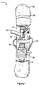
Referring to Figures 1 to 9 there is shown a first embodiment hose deployment
device 1, including a base 3 having sides 4 which in a contracted
configuration (see
Figures 1 and 2) secure together to define a space to receive a hose 10. The
sides 4 in an
expanded configuration (see Figures 3 to 6) extend outwardly away from each
other to
provide an opening 6 through which the hose 10 can move. Strap means 12 secure
the
hose 10 to the base 3 in the contracted configuration, as best seen in Figure
2. Upon
application of a fluid pressure to the inlet valve (not shown), the hose 10
expands urging
the strap means 12 to release the hose 10 from the base 3. The hose 10 urges
the sides 4
away from each other (as best seen in Figures 4 to 6), deploying the hose 10
in a coiled
configuration (see Figure 6) for use by a uscr. Rather than using pressure the
device 1
could also be deployed by a user manually and then pressurized after being
laid.
As best seen in Figure 6, the device 1 can deploy the hose 10 within a small
area
such as 2m2 in a coiled configuration. This is particularly advantageous in
stairwells or
the like. 'The device 1 further includes an additional strap means 15 to
secure the sides 4
together until use. In a preferred fonn, the base 3 is a fabric panel and each
side 4 is also
a fabric panel extending away from the base 3. The expansion of the hose 10
under
CA 02826287 2013-08-01
WO 2012/103595
PCT/AU2012/000099
9
pressure will also release the strap means 15, urging the sides 4 to fall
apart and away
from each other. The device 1 further includes means 20, such as handles,
straps or the
like so that the device 1 can be carried by a user or attached to a user, such
83 like a
backpack.
In a pre.ferred form, the pressure required at the inlet valve to open the
strap
means 12, 15 should be more than 400 kPa. The pressure could vary depending
upon the
size of the device 1 and its uses, In a preferred form, the sides 4 in a
contracted
configuration overlap each other. The strap means 12, 15 could include hook
and loop
type fasteners, press-stads or the Mos. The device could also include a strap
or fastening
means 25 to hold an outlet nozzle 27 on the device 1 (as best seen in Figure
1). The
device 1 could also include luminescent strips 211 or the like and a top cover
30 could also
be provided.
There is also provided herein a method of deploying a hose 10 by a hose
deployment device 1. Thc steps for deploying a hose 10 from the contracted
configuration to the expanded configuration. The steps in the preferred form
would
include carrying the hose deployment device 1 to a location of use, such as a
stairwell or
the like. Placing the device 1 on a surface and laying out the nozzle 27 and
opening the
top flap 30 (see Figure 2). In one embodiment a water source is attached to
the water
inlet valve (not shown) and the hose 10 is pressurised (see Figure 3). As the
hose 10 is
pressurised, the hose 10 expands urging the strap members 12, 15 apart to
release the hose
10. The hose 10 urges the sides 4 to fall away from each other (sce Figure 4),
deploying
the hose 1 0 in a coiled configuration (see Figure 6). A user would then carry
the nozzle
27 to the location of use towards a fire to be extinguished. Alternatively,
the device 1 can
be deployed manually by the user moving away from the base 3 rather than being
deployed by pressure.
Accordingly, there is shown herein a hose deployment device 1 that deploys a
hose 10 reliably, quickly, efficiently and with less movements to current
methods and fire
fighting procedures. That is, a simple plug and play device 1 with no
unrolling, or
unkinking. There are also no slaw angles for the water to jamb or kink. The
device 1
can be hoisted to a high point or carried to any location. The device 1 can be
deployed in
tight areas like stairwells or the like, is easily carryable on a back or by
hand and provides
a firc fighter or other emergency personnel a more strategic option when
considering how
CA 02826287 2013-08-01
WO 2012/103595
PCT/AU2012/000099
to fight a fire. As the device I only needs to be deployed within about two
square meters
it oan be deployed in a foyer, roof balcony, stairwell or the like. The device
I preferably
is manufactured of nylon, cotton or the like, however, should include fire
resistant
material. In the preferred form, the device 1 is made of a number of fabric
panels folded
together to enclose the hose 10, the panels secured together by straps 12, 15
until use.
Referring to Figures 7 to 9, the device 1 has a mechanism to securely house
the
hose inlet valve (not shown) and outlet nozzle 27, This housing 33 is purpose
built and is
secured with hook and loop type fasteners 70 to the device 1. The housing 33
(see Fig 8
for example) is placed around the hose inlet. The housing 33 has the loop
fasteners on
both sides 34. A securing strap 34 is comprised of a sump with hook fasteners.
The
securing strap 34 is permanently attached to the bottom flap 35. As the bottom
flap 35 is
closed the securing strap 34 is engaged to both sides of the housing 33. The
top flap 31 is
closed over the top of the housing 32. The top flap 31 is secured to the side
4 (see Figure
2) of the device 1. The housing 33 is opened first by pulling strap 37 (see
Figure 9) then
pulling securing strap 36 (see Figure 7).
The device 1 has the ability to contain and reliably deploy a second hose 10
away from a water some to the fire, thus allowing a hose line to be charged
and the
second hose 1 0 to coil on the spot Giving the user the ability to move into
the fire
effecb:d area more easily.
Referring to Figures 10 to 16 there is shown a second embodiment hose
deployment device 1, including a base 300 having sides 400 which in a
contracted
configuration (see Figures 10 and 11) secure together to define a space to
receive a hose
100. Upon disengagement of inlet/outlet valve securing strap 120 the hose 100
is fire to
exit the device 1. The device 1 can deploy the hose 100 within a narrow area
in a linear
configuration. This is particularly advantageous ill corridors, up or down
stairs or the
like. The device 1 further includes an additional strap means 150 to secure
the sides 400
together until use. In a preferred form, the base 300 is a fabric panel and
each side 400 is
also a fabric panel extending away from the base 300. The device 1 further
includes
means 200, s-uch as handles, straps or the like so that the device 1 Can be
carried by a user
or attached to a user, such as like a backpack.
CA 02826287 2013-08-01
WO 2012/103595
PCT/AU2012/000099
11
In a preferred form, the force required to dispatch the hose 100 from the
device 1
should be minimal to aid the operator in covering the required area as quickly
as possibk.
In. a preferred form, the sides 400 in a contracted configuration overlap each
other. The
strap means 700, 120, 150 could include hook and loop type fasteners, press-
studs or the
like. The device 1 could also include a strap or fastening means 250 to hold
an optional
breeching piece or the like. The device 1 could also include luminescent
strips 280 or the
like and a top cover 300 and bottom cover 300 could also be provided.
There is also described herein a method of deploying a hose 100 by a hose
deployment device 1. The steps for deploying a hose 100 can be seen by
proceeding from
the contracted configuration to an expanded linear configuration. The steps in
the
preferred form would include carrying the hose deployment device 1 to a
location of use,
such as a sta'rwell or the like. Placing the device 1 on a surface and opening
the covers
30 which include inlet/outlet valve hose tan seeming flaps 300 (see Figure
12). As the
operator moves from the initial deployment area the hose will automatically
deploy in the
correct fashion and lay on the travelled surfbee as the user moves away from
the device 1.
A user would then connect a nozzle or alternate piece of equipment (for
example, a gated
wye) 350 or the like to the remaining inlet/outlet valve of the hose 100.
Accordingly, there is shown herein a hose deployment device 1 that deploys a
hose 100 reliably, quioldy, efficiently and with less movements to current
methods and
fire fighting procedures. The device 1 is a simple plug and play device 1 with
no
unrolling, or unkinking required. There are also no sharp angles for the water
to jamb or
kink. The device 1 can be hoisted to a high point or carried by a user to any
location.
The device 1 can be deployed in tight areas such as stairwells or the like, b
easy to carry
on a back or by hand and provides a fire fighter or other emergency personnel
a more
strategic option when considering how to fight a fire. The device 1 can also
be deployed
in a foyer, roof balcony, stairwell or the like. The device 1 preferably is
manufactured of
nylon, cotton or the hie, however, should include fire resistant material. In
the preferred
form, the device 1 is made of a number of fabrics panels folded together to
enclose the
hose 10, the panels secured together by straps 700, 120, 150 until use. The
device 1 has a
further hose tail flap 310 (see Figure 16). This flap 310 contains the hose
100 and protects
it from the elements. It is removed when the hose 100 is to be deployed. The
device 1 is
CA 02826287 2013-08-01
WO 2012/103595
PCT/AU2012/000099
12
typiCally carried like a suitcase over a shoulder. The top flap is released
and the base is
allowed to deploy. The device 1 can store large hoses such as a "supply line".
The device I could include a tracking device (not shown) to locate the fire
fighter and/or the hose 10, 100 during operations within buildings,
underground or in low
visibility. The device 1 could also include audible or visual warning devices
28, 280.
This could include a form of identification that could be located within
thermal hnaging
or radio signals. The device 1 could also include a durable, waterproof or
different type
of material on the base 4, 40 for various uses. A flashing strobe or similar
device could
also be included.
The device 1 could also inch3de various pockets (not shown) made of various
materials to store auxiliary equipiment including but not limited to hose
spanners, glow
sticks or the like. Also the device 1 can include a back strap (not shown)
which can be
disconnected by carabeena style clips and converted into a purpose built hose
securing
strap. This is done by passing one end around the hose 100 through a loop on
the other
end, then tightened into a "larks head" style knot The free end of the strap
can be tied or
clipped onto a fire stair, balcony or the hie. As the hose 100 exits the
device 1 it
continually rubs on one spot. A reinforced patch, material or the hie (for
example leather
or plastic) could be included.
Referring to Figures 17 to 38 there is shown a third embodiment hose
deployment device 801, including a base 803 having sides 804 which in a
contracted
configuration is secured together to define a space to receive a hose, not
shown. The hose
will typically be held in a coiled configuration by the device 801 and
deployed in a
manner similar to the first embodiment described above.,
The sides 804 extend outwardly away from each other to provide a deployed
configuration 806 allowing the hose to be moved away from the base 803. Strap
means,
not shown, secure the hose to the base 803 in the contracted configuration.
The device 801 further includes means 820, such as handles, straps or the like
so
that the device 801 can be carried by a user or attached to a user, such as
like a backpack
The device 801 has a mechanism to securely house a coupling and a nozzle (not
shown). This housing 833 is purpose built and is secured with hook and loop
type
CA 02826287 2013-08-01
WO 2012/103595
PCT/AU2012/000099
13
fasteners 870 to the device 801. The housing 833 is placed arotmd th.e hose
inlet The
housing 833 has the loop fasteners on both sides 831. A securing strap 834 is
comprised
of a strap with book fasteners. The securing strap 834 is permanently attached
to the
bottom flap 835. As the bottom flap 835 is closed the securing strip 834 is
engaged to
both sides of the housing 833. The housing 833 is opened by pulling the
securing strap
834 to separate the respective hook and loop fasteners.
The device 801 includes wedge pockets 811 to store wedges 813 (shown in
Figures 23 and 24). The device 801 further includes a pocket 816 to hold, for
example,
operating instructions. Insulating means 817 (shown in Figure 22), which in
use will
insulate/ separate the coupling from the nozzle, is provided to protect the
nozzle within
the housing 833.
The device includes a shoulder strap 818 which is scoured to a loop 819 via a
clip 821 as shown in Figures 2,8 to 35. A hose securing means 822, shown in
Figures 36
to 38 is sheathed within a packet 823 within the shoulder strap 818. The hose
securing
means 822 comprises a strap 824 with a clip 826 and loop 827. The clip 826,
here a D-
clip, and loop 827 can, for example, be used to secure a section of a hose to
a railing
when the hose is to be suspended from the railing.
A fourth embodiment hose deployment device 901 is shown in Figures 39 to 43.
The device 901 operates in a manner similar to the second embodiment described
above.
The device 901 houses a flaked hose which is deployed by having a user puling
sections
of the hose from the device as the user carries the device 901 across a
distance. To
deploy the hose, a release flap 910 is moved from a closed position, shown in
Figure 42,
to an open position, shown in Figure 43.
The device 901 in particular includes opposing !ides, one of which is shown
and
depicted with the reference numeral 904, extendable between a retracted
position, shown
in Figure 41 and an extended position, shown in Figure 40. By having such
extendable
sides it is possible to increase the vohnne of the device 901.
Figures 44 to 48 show a coupling holder 950 that is to be secured to the
exterior
of the device 901. The coupling holder 950 is shaped as shown and is adapted
to secure a
hose coupling to the device 901. The coupling holder 950 can be folded from a
compressed configuration, shown in Figures 44 to 46, to an expanded
configuration,
CA 02826287 2013-08-01
WO 2012/103595
PCT/AU2012/000099
14
shown in Figures 47 and 48, when a coupling is to be secured therein. In the
expanded
configuration the coupling holder 950 provides a pocket 952 which is closed
with a flap
954.
Figures 49 to 55 show a fifth embodiment hose deployment device 1000. The
device includes a base 1003, sides 1004 which extend from the base, a cover
1005
secured to a side 1004, and a closure 1007 extending from the base. The base
1003 and
sides 1004 define a holding area in which a section of a hose is in use held,
preferably in a
coiled configuration. The cover 1005 includes hose holding means 1008. The
holding
means of this embodiment comprises two rows of opposing pockets 1010, each row
including a number of pockets. In use a section of the hose is held, in a
flaked
configuration between the rows of pockets. This is shown in Figure 52.
As shown in Figure 51, the closure 1007 is secured to the cover 1005 with a
hook and loop fastener arrangement 1011. Figure 53 in turn shows that the
cover 1005 is
secured to the sides 1004 with a hook and loop fastener arrangement 1012.
The device 1000 is preferably compact in size so as to be stored within a
container located at a fire hydrant
Although the invention has been described with reference to specific examples,
it
will be appreciated by those skilled in the art that the invention may be
embodied in many
other forms.