Note : Les descriptions sont présentées dans la langue officielle dans laquelle elles ont été soumises.
CA 02826394 2013-09-05
259557-2
ROLLBACK PROTECTION SYSTEM AND METHOD
BACKGROUND
TECHNICAL FIELD
[0001] Embodiments of the invention relate generally to control systems
for rail
vehicles.
DISCUSSION OF ART
[0002] Rail car switching, shunting, and classification are integral
aspects of rail
freight operations. These procedures are performed in switching yards or
classification
yards, which include multiple rail tracks branching from one or more lead
tracks and
joining together at one or more exits. To maximize operational efficiency,
several cars or
trains of cars are typically moving simultaneously along different branches
within a yard.
Due to the presence of multiple stationary rail cars or stub trains on
intervening tracks, an
operator in a locomotive moving on a first track may not be able to see moving
cars on a
track branching from the first track. Accordingly, locomotive operators may
coordinate
their actions via a yardmaster stationed in a control tower overlooking the
yard.
[0003] Three-way communication between operators and a yardmaster can
potentially introduce lag time and error, which are undesirable while moving
multiple
pieces of heavy rail equipment. As such, some yards include systems by which a
yardmaster may remotely control and coordinate movement of multiple stub
trains
("tower control systems").
[0004] In situations where the train may be on a grade (as may be found
in
connection with mining operations), there is a known tendency for "rollback"
where the
train moves opposite the applied tractive power. While rollback can often be
quickly
detected and corrected by an onboard operator, the phenomenon is more
difficult to
detect and slower to correct from a remote location such as would be occupied
by a tower
control system operator. Yet as discussed above, rail yard operations,
generally, can be
accomplished more efficiently by a tower control system operator than by an
onboard
1
CA 02826394 2013-09-05
259557-2
crew. As will be appreciated, it is inefficient and undesirable to
continuously crew a train
in a rail yard, solely for the purpose of preventing rollback, particularly
where the
onboard crew might otherwise interfere with tower control system operation. As
such, it
is desirable to provide a tower control system that includes a specific and
automated
method to prevent rollback.
BRIEF DESCRIPTION
[0005] In embodiments, a system for controlling a rail vehicle includes
an off-
board control unit that is configured for communication with an on-board
transceiver,
which is mounted in the rail vehicle. The off-board control unit is further
configured to
receive a first signal indicative of a location of the rail vehicle and to, in
response to the
indicated location of the rail vehicle matching a pre-defined list of rollback
locations,
send to the on-board transceiver a second signal indicative of a tractive
effort parameter
corresponding to at least the indicated location of the rail vehicle.
[0006] In aspects, a method, e.g., a method for preventing rollback of a
rail
vehicle from a stopped condition, includes receiving a first signal indicative
of the rail
vehicle's location and, in response to the first signal, selecting from a
lookup table one of
a first plurality of pre-determined values of a braking parameter and
selecting from the
lookup table one of a second plurality of pre-determined values of a tractive
effort
parameter. The method then includes transmitting to the rail vehicle a second
signal
ordering movement of the rail vehicle from the stopped condition. The second
signal
includes the selected value of the braking parameter for controlling
application of brakes
of the rail vehicle and the selected value of the tractive effort parameter
for establishing
tractive effort of the rail vehicle.
[0007] In embodiments, a system for controlling a rail vehicle includes
an on-
board transceiver mounted in the rail vehicle and operatively connected with
at least one
traction motor and at least one brake of the rail vehicle. The on-board
transceiver is
configured to receive from an off-board control unit a first signal for
establishing a
rollback prevention mode. In its rollback prevention mode, the on-board
transceiver is
2
1
CA 02826394 2013-09-05
259557-2
configured to receive from the off-board control unit a second signal
indicative of a
required tractive effort and a third signal indicative of a required braking
force, and to
control maintaining the required braking force until attaining the required
tractive effort.
[0008] In embodiments, a system for controlling a rail vehicle includes
an off-
board control unit that is not mounted in the rail vehicle and an on-board
transceiver that
is mounted in the rail vehicle. The off-board control unit is configured to
receive a first
signal indicative of a location of the rail vehicle and to send, in response
to the first
signal, a second signal indicative of a minimum tractive effort parameter and
a third
signal indicative of a braking parameter. The on-board transceiver is
operatively
connected with at least one traction motor and at least one brake of the rail
vehicle, and is
configured to receive the second and third signals from the off-board control
unit. The
on-board transceiver is further configured to control maintaining the brake
output at or
above a level of the braking parameter until the traction motor output at
least matches a
level of the minimum tractive effort parameter.
DRAWINGS
[0009] The present invention will be better understood from reading the
following
description of non-limiting embodiments, with reference to the attached
drawings,
wherein below:
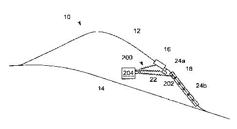
[0010] FIG. 1 shows in schematic view a bulk cargo loading/unloading
operation
including a tower control system according to one aspect of the present
invention.
[0011] FIG. 2 shows in schematic view a rollback phenomenon.
[0012] FIG. 3 shows in schematic view a tower control system according to
an
embodiment of the present invention.
[0013] FIG. 4 shows in schematic view details of the tower control system
shown
in FIG. 3.
3
,
CA 02826394 2013-09-05
259557-2
[0014] FIG. 5 shows in schematic view operation of the tower control
system
shown in FIGS. 3 and 4.
[0015] FIGS. 6A-6C show in schematic view a rollback prevention mode of
the
tower control system, according to aspects of the present invention.
[0016] FIG. 7 shows in schematic view a rollback prevention mode of the
tower
control system, according to other aspects of the present invention.
[0017] FIGS. 8A-8B show in schematic view another rollback prevention
mode
of the tower control system, according to other aspects of the present
invention.
DETAILED DESCRIPTION
[0018] Reference will be made below in detail to exemplary embodiments of
the
invention, examples of which are illustrated in the accompanying drawings.
Wherever
possible, the same reference characters used throughout the drawings refer to
the same or
like parts. Although exemplary embodiments of the present invention are
described with
respect to rail vehicles within a rail yard, embodiments of the invention are
also
applicable for use with rail vehicles, generally.
[0019] FIG. 1 shows in schematic view a bulk cargo loading/unloading
operation
that includes a loop (or other section) of track 12 connected from a main rail
line 14
through loading/unloading equipment 16. In the loading/unloading equipment 16,
coal /
iron ore / other bulk products are dumped into or out of cars or wagons 18 of
a train or
other rail vehicle consist 20 that is located at a location on the loop of
track 12. (A rail
vehicle consist is a group of rail vehicles that are mechanically linked to
travel together
along a track.) For example, the loading/unloading equipment 16 may include a
dumper
chute (which directs a continuous flow of bulk material into a wagon
positioned below
the chute) or a rotary dumper cage (which inverts a wagon positioned in the
dumper
cage).
4
1
CA 02826394 2013-09-05
259557-2
[0020] When the rail vehicle consist 20 approaches the unloading
equipment 16,
each wagon 18 is in turn moved into position by indexing equipment 22. Once a
wagon
18 is positioned, independent and/or automatic brakes are set to hold the rail
vehicle
consist 20 at a fixed location. ("Independent brakes" means the brakes of each
locomotive or other powered rail vehicle 24 (rail vehicle capable of self
propulsion)
within the rail vehicle consist 20, which can be controlled independently of
the
"automatic brakes" that are installed on each wagon 18. The automatic brakes
installed
on the wagons 18 are operable all together and are also referred to as "train
brakes."
Together, the independent and automatic brakes compose a "braking system,"
which may
be operated all together or piece by piece.)
[0021] In order to move the whole rail vehicle consist 20 forward, so as
to bring a
next wagon 18 into position, the brakes must be released while tractive power
is applied
when all or part of the rail vehicle consist 20 is located on a grade or
incline, then
rollback (as shown schematically in FIG. 2) can be caused by the weight of the
rail
vehicle consist 20 exceeding the instantaneous torque provided by electric
traction
motors. Once rollback starts to happen, increasing backward movement 611 of
the rail
vehicle consist 20 requires increasingly larger forward torque (ordered
movement 515) in
order to stop the rail vehicle consist. Frequently, brakes must be reapplied
and another
attempt must be made at forward motion.
[0022] Rollback of the rail vehicle consist 20, as illustrated
schematically in FIG.
2, can lead to impacts between the rail vehicle consist 20 and the
loading/unloading
equipment 16. Rollback also can lead to a condition where the rail vehicle
consist 20
rests against the loading/unloading equipment 16 with sufficient force to
interfere with
operation of the equipment. Such impacts or interferences can damage the rail
vehicle
consist and/or the loading/unloading equipment, causing repair expense and
downtime.
[0023] With reference to FIG. 3, aspects of the invention relate to a
system for
controlling a rail vehicle 24a, by which rollback of the rail vehicle is
prevented. In
particular aspects, the system includes an on-board transceiver 202 of the
rail vehicle 24a.
,
CA 02826394 2013-09-05
259557-2
The on-board transceiver 202 sends and receives signals in communication with
an off-
board control unit 204. The on-board transceiver 202 also includes hardware
and
software for controlling operation of the rail vehicle 24a. In particular, the
on-board
transceiver 202 is operatively connected for controlling traction and braking
of the rail
vehicle 24a. The on-board transceiver 202 can be configured in various modes
of
operation. For example, in a rollback prevention mode, the on-board
transceiver 202
adjusts traction motors 206 of the rail vehicle 24a to achieve a pre-
determined minimum
tractive effort prior to releasing a braking system 208 of the rail vehicle.
[0024] FIG. 4 illustrates details of a tower control system 200 according
to
embodiments of the invention. The tower control system may include a tower
equipment
module 210 that houses a tower transceiver 212 for intermediating
communication
between the off-board control unit 204 and the on-board transceiver 202. The
tower
equipment module also may house an integrated processor module (IPM) 214 and a
power converter 216. In some embodiments, the power converter receives 120 Vac
and
supplies 13.6 and 72 Vdc.
[0025] As shown in FIG. 4, according to one embodiment of the invention,
the
off-board control unit 204 includes multiple displays 218 on which a desired
speed
setting and measured vehicle speed are shown, as well as an operator control
unit (OCU)
220. Each display is a remote session based device connected to the IPM 214,
which
handles all control signals and consist data for the operator displays 218.
The OCU 220
includes at least the following controls: a multi-position selector 222 as
well as a PARK
button 224 and a STOP button 226. In some embodiments, the OCU also may
include an
auxiliary display 228 as shown. In some embodiments, the selector 222 may
include a
dial, a switch, a position encoder, or any equivalent device suitable for
selecting among
more than two options. In some embodiments, the buttons 224, 226 may be spring-
return
push buttons. Toggle switches, sliders, or the like are equally suitable. In
certain
embodiments, the functions of the two buttons 224, 226 may be combined into a
single
component, for example, a three-way selector switch. In select embodiments the
functions of the two buttons 224, 226 may be combined into the selector 222,
or the
6
CA 02826394 2013-09-05
259557-2
buttons may be mounted on the selector. The selector 222 as well as the
buttons 224, 226
and the optional display 228 are shown and described herein as being
physically separate
components within an assembled unit, however, one of ordinary skill will
appreciate that
the displays 218 and the OCU 220 equally can be implemented partly or entirely
via a
single advanced interface such as a touch-screen.
[0026] The displays 218, 228 and the OCU 220 are coordinated by a
computing
device 230. "Computing device" as used herein refers to either a general
purpose
integrated circuit, a custom ASIC, an FPGA, a custom analog circuit, or other
like device.
As shown in FIG. 3, the computing device 230 is connected with the integrated
processor
module 214 via a point-to-point high-level data link control ("HDLC") layer.
In certain
embodiments, the functionality of the computing device 230 may be implemented
in the
IPM 214 itself.
[0027] As illustrated in FIG. 5, the computing device 230 is configured
to
implement a continuous-loop control process 400 for generating and sending
commands
407 to the on-board transceiver 202 via the IPM 214 and the tower transceiver
212. In
implementation of the process 400, the computing device 230 makes use of a
working
memory 401. The working memory 401 may be composed of any electronically or
optically read-writeable media, such as EEPROM, NAND flash, SDRAM, a hard
drive,
an optical disc, vacuum tubes, a capacitor bank, or other equivalent
structures apparent to
those of ordinary skill.
[0028] Each iteration of the process 400 includes a step 402 of checking
and
setting a mode of operation 403 of the off-board control unit 204. For
example, pressing
one of the STOP button 224 or the PARK button 226 establishes a corresponding
mode
of operation 403 of the off-board control unit 204 that causes the computing
device 230
to generate and send to the on-board transceiver 202, via the tower
transceiver 212,
commands that idle the traction power system and that order braking of a
locomotive 24
(or other powered rail vehicle) or of the entire rail vehicle consist 20,
respectively.
7
CA 02826394 2013-09-05
259557-2
[0029] After checking the mode of operation, the process 400 proceeds to
a step
404 of receiving signals from the on-board transceiver 202 and/or from other
sources
within the rail yard 10 including the unloading equipment 16 or the indexing
equipment
22. (Here "rail yard" is meant to include any arrangement of tracks off of a
main line,
including humpyards, sorting yards, or loading/unloading operations as
discussed above.)
[0030] The computing device 230 stores received signals in the working
memory
401 as on-board data 405. The on-board data 405 may include a measured speed
"M" as
well as indications that braking has been applied or that a braking order has
been received
in the rail vehicle where the on-board transceiver is installed. The measured
speed "M"
may be obtained by the on-board transceiver 202 from a control system on some
rail
vehicles (e.g., a locomotive control system on some locomotives) or from a
trainline
interface module (TIM) on some other locomotives or other rail vehicles.
[0031] Next, at a step 406 the computing device 230 generates commands
407 to
be sent to the on-board transceiver. The commands 407 are generated according
to an
algorithm, which corresponds to the mode of operation 403. The algorithm
generates the
commands 407 with reference to the on-board data 405 and further with
reference to
control data and internal signals 408 that are stored in the working memory
401.
Exemplary modes of operation 403, and on-board data 405, have been discussed
above.
The control data and internal signals 408 may include the braking parameter
"P", a preset
speed limit "L", a selector position "H", and an ordered speed "0". At a step
410 the
tower control system 200 then sends the commands 407 to the on-board
transceiver 202
before looping back to again check for control data input from the off-board
control unit
204.
[0032] According to aspects of the present invention, the computing
device 230 is
configured to establish a rollback prevention mode of operation and to execute
a first
algorithm 500, as shown in FIG. 6A, in response to the lead locomotive 24a (or
other lead
powered rail vehicle) being halted at any location within one or more pre-
determined
areas of the rail yard 10. As part of the first algorithm 500, the computing
device 230
8
CA 02826394 2013-09-05
259557-2
directs the on-board transceiver 202 to execute a second algorithm 600, as
shown in FIG.
6B. Thus, the two figures 5 and 6 should be considered together.
[0033] FIG. 6A shows that at step 502 of the algorithm 500, the computing
device
230, within the off-board control unit 204, checks whether the lead locomotive
24a (or
other lead powered rail vehicle) is stopped. If not, the computing device 230
will exit the
algorithm. At step 504, the computing device 230 receives a signal 505
indicative of the
location of the lead locomotive 24a (or other lead powered rail vehicle), and
compares the
indicated location to a rollback prevention map or table 506. In case the
indicated
location is not within the mapped area or is not listed in the table, then the
computing
device 230 exits the algorithm 500. However, in case the indicated location is
mapped on
the rollback prevention map 504, or listed in an rollback prevention locations
lookup
table, then at step 508 the computing device 230 inserts a rollback prevention
mode
signal into the commands 407. This signal initiates in the on-board
transceiver 202 a
rollback prevention mode 600, as shown in FIG. 6. Under the rollback
prevention mode
600, the on-board transceiver 202 is configured to receive certain additional
signals from
the off-board control unit 204, as follows.
[0034] Still referring to FIG. 6A, at step 510, the computing device 230
accesses
the rollback prevention map 504, or an equivalent lookup table, to find a
minimum
tractive effort parameter 511 corresponding to the location 501. For example,
the
minimum tractive effort parameter 511 may be determined during commissioning
of the
tower control system 200. The computing device 230 then inserts into the
commands 407
a signal that encodes the minimum tractive effort parameter 511.
[0035] At step 512, the computing device 230 accesses the rollback
prevention
map 504, or an equivalent lookup table, to find a braking parameter 513
corresponding to
the location 501. For example, the braking parameter 513 may be determined
during
commissioning of the tower control system 200. The computing device 230 then
inserts
into the commands 407 a signal that encodes the braking parameter 515.
9
CA 02826394 2013-09-05
259557-2
[0036] At step 514 the computing device 230 receives from the multi-
position
selector 222 a signal ordering movement of the lead locomotive 24a (or other
lead
powered rail vehicle). The computing device 230 generates an ordered movement
515
and forwards a corresponding signal to the on-board transceiver 202. The
computing
device 230 then proceeds to step 516 of waiting to receive on-board
transceiver status
signals 601.
[0037] Referring to FIG. 6B, at step 602, the on-board transceiver 202
receives
the rollback prevention mode signal. At step 604, the on-board transceiver 202
receives
the minimum tractive effort parameter 511 and the braking parameter 513. At
step 605,
the on-board transceiver 202 applies at least the brakes of the lead
locomotive 24a (or
other lead powered rail vehicle), and possibly additional brakes of the rail
vehicle consist
20, according to the braking parameter 513. At step 606, the on-board
transceiver 202
receives the ordered movement 515 and increments a throttle notch setting
("throttle up")
until a monitored tractive effort 607 matches the minimum tractive effort
parameter 511.
Then at step 608, the on-board transceiver 202 releases at least the brakes
208 of the lead
locomotive 24a (or other lead powered rail vehicle). At step 608 the on-board
transceiver
202 also releases any other brakes that are applied, for example, the
automatic brakes of
the rail vehicle consist 20 in case the rail vehicle consist is in a parked
condition.
Immediately the on-board transceiver 202 proceeds to step 610 of checking
whether the
ordered movement 515 corresponds to a monitored movement 611, which includes a
direction of motion as well as the measured speed "M" that was discussed with
reference
to FIG. 4.
[0038] In case the monitored movement 611 is matched with the ordered
movement 515, then the on-board transceiver 202 declares a "movement" status
signal at
step 612. In case the monitored movement 611 does not match the ordered
movement
515, then at step 614 the on-board transceiver 202 declares a "rollback"
status signal and
proceeds to apply automatic and independent brakes ("emergency braking") at
step 616.
CA 02826394 2013-09-05
259557-2
[0039] In some embodiments, step 610 of checking for a match is
accomplished
by instantaneous or "snapshot" comparison of the directions of measured
movement 611
and ordered movement 515. Thus, for example, in case the speed of ordered
movement
515 is +0.5 mph (+0.2 m/s), while the monitored movement 611 is -0.2 mph (-
0.09m/s)
(directions do not match), then a rollback is declared.
[0040] In other embodiments, step 610 is accomplished in a first noise-
managed
mode by comparing ordered movement 515 to monitored speed and direction 611 on
a
time integral basis, using one or more threshold value criteria. That is,
referring to FIG.
6C, monitored movement 611 is continually compared to a first threshold value
630. In
case the first threshold value is exceeded, at step 632 the monitored movement
611 is
integrated over a pre-determined period 634 to produce a cumulative traveled
distance
636, while at step 638 the ordered movement is integrated over the same period
to
produce a cumulative ordered distance 640. Then at step 642 a second threshold
value
644 is compared to the cumulative traveled distance 636, or to a difference
646 between
the cumulative traveled distance and the cumulative ordered distance 640. For
example,
the first threshold value 630 may be as small as -0.02 mph (0.009 m/s), the
pre-
determined period 634 may be 10 seconds, while the second threshold value 644
may be
as large as 33 ft (10 m). The threshold values 630, 644, and the time period
634, are
configurable at least at commissioning of the tower control system 200.
[0041] Referring back to FIG. 6A, in case the signal received at step 516
indicates
proper movement, the computing device 230 exits the algorithm 500. On the
other hand,
in case the signal received at step 516 indicates rollback, the computing
device 230
performs step 518 of displaying an alert.
[0042] FIG. 7 shows more generally the algorithms 500 and 600, including
additional steps 702, 704 of monitoring speed and direction of the rail
vehicle consist 20
as well as optional steps 706, 708 of displaying a braking alert and awaiting
an operator
response or confirmation, prior to step 614 of declaring rollback.
11
CA 02826394 2013-09-05
259557-2
[0043] FIGS. 8A-8B show another implementation of the algorithms 500,
600,
wherein certain steps are performed in the computing device 230, rather than
at the on-
board transceiver 202. In particular, FIG. 8A shows that step 606 (throttling
up to match
the monitored tractive effort 607 to the minimum tractive effort parameter
511) and step
608 (releasing brakes) can be accomplished by remote commands from the off-
board
control unit 204, rather than autonomously by the on-board transceiver 202.
Meanwhile
FIG. 8B shows that the function of step 610 (comparing ordered movement to
monitored
movement) still can be accomplished by the on-board transceiver 202 using
sensors
aboard the rail vehicle 24a.
[0044] Thus, in embodiments, a system for controlling a rail vehicle
includes an
off-board control unit that is configured for communication with an on-board
transceiver,
which is mounted in the rail vehicle. The off-board control unit is further
configured to
receive a first signal indicative of a location of the rail vehicle and to, in
response to the
indicated location of the rail vehicle matching a pre-defined list of rollback
locations,
send to the on-board transceiver a second signal indicative of a tractive
effort parameter
corresponding to at least the indicated location of the rail vehicle. In
select embodiments,
the system may also include the on-board transceiver, which may be configured
to adjust
and monitor a tractive effort of the rail vehicle and to control applying
brakes of the rail
vehicle until the monitored tractive effort at least matches the tractive
effort parameter.
In such embodiments, the off-board control unit also may be configured to set
a braking
parameter based on the indicated location of the rail vehicle and to transmit
the braking
parameter to the on-board transceiver, while the on-board transceiver may be
configured
to control applying the brakes according to the braking parameter. Further,
the on-board
transceiver may be configured to monitor rail vehicle movement, to compare the
monitored movement to an ordered movement, and to control application of
emergency
brakes in response to a mismatch of the monitored movement and the ordered
movement.
For example, the on-board transceiver may be configured to control application
of the
emergency brakes according to the braking parameter. In select embodiments,
the on-
board transceiver may be configured to compare the monitored movement to the
ordered
12
CA 02826394 2013-09-05
259557-2
movement on a time integral basis. In some embodiments, the on-board
transceiver also
may be configured to send to the off-board control unit, in response to a
mismatch of the
monitored movement and the ordered movement, a request for a third signal to
apply the
brakes of the rail vehicle. In such embodiments, the off-board control unit
may be
configured to, in response to the request received from the on-board
transceiver, display
an operator prompt and receive an operator input whether to apply the brakes.
The third
signal for applying the brakes may include a braking parameter based on the
indicated
location of the rail vehicle. Further, the off-board control unit may be
configured to
monitor tractive effort of the rail vehicle, and to send the on-board
transceiver a fourth
signal for releasing the brakes, once the tractive effort of the rail vehicle
matches or
exceeds the tractive effort parameter. However, in some embodiments, the off-
board
control unit may be configured to send the fourth signal for releasing the
brakes, pursuant
to a request received from the on-board transceiver. In some embodiments, the
off-board
control unit may be configured to send a fifth signal for establishing a
rollback prevention
mode, based on the indicated location of the rail vehicle matching the pre-
defined list of
rollback locations; the on-board transceiver may be configured to establish a
rollback
prevention mode on receipt of the fifth signal from the off-board control
unit.
[0045] In aspects, a method, e.g., a method for preventing rollback of a
rail
vehicle from a stopped condition, includes receiving a first signal indicative
of the rail
vehicle's location and, in response to the first signal, selecting from a
lookup table one of
a first plurality of pre-determined values of a braking parameter and
selecting from the
lookup table one of a second plurality of pre-determined values of a tractive
effort
parameter. The method then includes transmitting to the rail vehicle a second
signal
ordering movement of the rail vehicle from the stopped condition. The second
signal
includes the selected value of the braking parameter for controlling
application of brakes
of the rail vehicle and the selected value of the tractive effort parameter
for establishing
tractive effort of the rail vehicle. In some aspects, the method also includes
receiving the
second signal at the rail vehicle, and, in response to the second signal,
applying the
brakes of the rail vehicle, according to the selected value of the braking
parameter;
13
CA 02826394 2013-09-05
259557-2
establishing the tractive effort of the rail vehicle, according to the
selected value of the
tractive effort parameter; and, releasing the brakes of the rail vehicle to
establish
movement of the rail vehicle from the stopped condition. In certain aspects,
the first
signal is received at an off-board control unit that is not installed on the
rail vehicle. In
select aspects, the second signal is transmitted from the off-board control
unit to an on-
board transceiver that is installed on the rail vehicle.
[0046] Embodiments include a system for controlling a rail vehicle, which
includes an on-board transceiver mounted in the rail vehicle and operatively
connected
with at least one traction motor and at least one brake of the rail vehicle.
The on-board
transceiver is configured to receive from an off-board control unit a first
signal for
establishing a rollback prevention mode. In its rollback prevention mode, the
on-board
transceiver is configured to receive from the off-board control unit a second
signal
indicative of a required tractive effort and a third signal indicative of a
required braking
force, and to control maintaining the required braking force until attaining
the required
tractive effort. The on-board transceiver may be further configured to control
release of
the braking force on attaining the required tractive effort, to monitor
movement of the rail
vehicle, to compare the monitored movement to an ordered movement, and to
control
application of the required braking force according to the third signal, in
case the
monitored movement does not match the ordered movement. In certain
embodiments,
the on-board transceiver may be configured to compare the monitored movement
to the
ordered movement on a time integral basis.
[0047] In other embodiments, a system for controlling a rail vehicle
includes an
off-board control unit that is not mounted in the rail vehicle and an on-board
transceiver
that is mounted in the rail vehicle. The off-board control unit is configured
to receive a
first signal indicative of a location of the rail vehicle and to send, in
response to the first
signal, a second signal indicative of a minimum tractive effort parameter and
a third
signal indicative of a braking parameter. The on-board transceiver is
operatively
connected with at least one traction motor and at least one brake of the rail
vehicle, and is
configured to receive the second and third signals from the off-board control
unit. The
14
CA 02826394 2013-09-05
259557-2
on-board transceiver is further configured to control maintaining the brake
output at or
above a level of the braking parameter until the traction motor output at
least matches a
level of the minimum tractive effort parameter.
[0048] It will be appreciated that the invention is not limited by the
preceding
description, which is intended to be illustrative, and not restrictive. For
example, the
above-described embodiments (and/or aspects thereof) may be used in
combination with
each other. In addition, many modifications may be made to adapt a particular
situation
or material to the teachings of the invention without departing from its
scope. While the
dimensions and types of materials described herein are intended to define the
parameters
of the invention, they are by no means limiting and are exemplary embodiments.
Many
other embodiments will be apparent to those of skill in the art upon reviewing
the above
description. The scope of the invention should, therefore, be determined with
reference
to the appended claims, along with the full scope of equivalents to which such
claims are
entitled. In the appended claims, the terms "including" and "in which" are
used as the
plain-English equivalents of the respective terms "comprising" and "wherein."
Moreover, in the following claims, terms such as "first," "second," "third,"
"fourth,"
"fifth," "upper," "lower," "bottom," "top," etc. are used merely as labels,
and are not
intended to impose numerical or positional requirements on their objects.
Further, the
limitations of the following claims are not written in means-plus-function
format and are
not intended to be interpreted based on 35 U.S.C. 122, sixth paragraph,
unless and until
such claim limitations expressly use the phrase "means for" followed by a
statement of
function void of further structure.
[0049] This written description uses examples to disclose several
embodiments of
the invention, including the best mode, and also to enable one of ordinary
skill in the art
to practice the embodiments of invention, including making and using any
devices or
systems and performing any incorporated methods. The patentable scope of the
invention
is defined by the claims, and may include other examples that occur to one of
ordinary
skill in the art. Such other examples are intended to be within the scope of
the claims if
they have structural elements that do not differ from the literal language of
the claims, or
CA 02826394 2013-09-05
259557-2
if they include equivalent structural elements with insubstantial differences
from the
literal languages of the claims.
[0050] As used herein, an element or step recited in the singular and
proceeded
with the word "a" or "an" should be understood as not excluding plural of said
elements
or steps, unless such exclusion is explicitly stated. Furthermore, references
to "one
embodiment" of the present invention are not intended to be interpreted as
excluding the
existence of additional embodiments that also incorporate the recited
features. Moreover,
unless explicitly stated to the contrary, embodiments "comprising,"
"including," or
"having" an element or a plurality of elements having a particular property
may include
additional such elements not having that property.
[0051] While there have been described herein what are considered to be
preferred and exemplary embodiments of the present invention, other
modifications of
these embodiments falling within the invention described herein shall be
apparent to
those skilled in the art.
16