Note : Les descriptions sont présentées dans la langue officielle dans laquelle elles ont été soumises.
CA 02826935 2013-08-08
WO 2012/109481 PCT/US2012/024541
ELECTRIC FIELD CONTROL OF TWO OR MORE
RESPONSES IN A COMBUSTION SYSTEM
CROSS-REFERENCE TO RELATED APPLICATIONS
The present application claims priority benefit under 35 USC 119(e) to U.S.
Provisional Application Serial No. 61/441,229; entitled "ELECTRIC FIELD
CONTROL OF TWO OR MORE RESPONSES IN A COMBUSTION SYSTEM",
invented by Thomas S. Hartwick, David B. Goodson, and Christopher A. Wiklof;
filed
on February 9, 2011; which is co-pending herewith at the time of filing, and
which, to
the extent not inconsistent with the disclosure herein, is incorporated by
reference.
lo
OVERVIEW
According to an embodiment, at least one first electric field may be
controlled
to drive a first response and at least one second electric field may be
controlled to
drive a second response in a heated volume of a combustion system. The
responses may be chemical or physical. A first portion of the heated volume
may
correspond to at least one combustion reaction zone. A second portion of the
heated volume may correspond to a heat transfer zone, a pollution abatement
section, and/or a fuel delivery section.
The at least one first and at least one second electric fields may include one
or more DC electric fields, one or more AC electric fields, one or more pulse
trains,
one or more time-varying waveforms, one or more digitally synthesized
waveforms,
and/or one or more analog waveforms.
One or more sensors may be disposed to sense one or more responses to
the electric fields. For example, the first electric field may be driven to
maximize
combustion efficiency. Additionally or alternatively, the first response may
include
swirl, mixing, reactant collision energy, frequency of reactant collisions,
luminosity,
thermal radiation, and stack gas temperature. The second electric field may be
driven to produce a second response different from the first response. For
example,
the second response may select a heat transfer channel, clean combustion
products
from a heat transfer surface, maximize heat transfer to a heat carrying
medium,
precipitate an ash, minimize nitrogen oxide output, and/or recycle unburned
fuel.
1
CA 02826935 2013-08-08
WO 2012/109481 PCT/US2012/024541
Accordingly, the second response may include driving hot gases against or
along or
away from one or more heat transfer surfaces, precipitating ash, driving an
oxide of
nitrogen-producing reaction to minimum extent of reaction, activating fuel,
and/or
steering fuel particles.
A controller may modify at least one of the first or second electric fields
responsive to detection of at least one input variable and/or at least one
received
sensor datum. For example, the at least one input variable includes fuel flow
rate,
electrical demand, steam demand, turbine demand, and/or fuel type.
lo BRIEF DESCRIPTION OF THE FIGURES
FIG. 1 is a diagram illustrating a combustion system configured to select two
or more responses from respective portions of a heated volume using electric
fields,
according to an embodiment.
FIG. 2 is a diagram illustrating a combustion system configured to select two
or more responses from respective portions of a heated volume using electric
fields,
according to another embodiment.
FIG. 3 is a block diagram of a controller for the system of FIGS. 1-2,
according to an embodiment.
FIG. 4 is a flow chart showing a method for maintaining one or more
programmable illustrative relationships between sensor feedback data and
output
signals to the electrodes, according to an embodiment.
FIG. 5 is a block diagram of a combustion system including a controller to
control fuel, airflow, and at least two electric fields produced in respective
portions of
a heated volume, according to an embodiment.
FIG. 6 is a diagram of a system using a plurality of controller portions to
drive
respective responses from portions of a combustion system, according to an
embodiment.
DETAILED DESCRIPTION
In the following detailed description, reference is made to the accompanying
drawings, which form a part hereof. In the drawings, similar symbols typically
identify similar components, unless context dictates otherwise. The
illustrative
embodiments described in the detailed description, drawings, and claims are
not
meant to be limiting. Other embodiments may be utilized, and other changes may
2
CA 02826935 2013-08-08
WO 2012/109481 PCT/US2012/024541
be made, without departing from the spirit or scope of the subject matter
presented
herein.
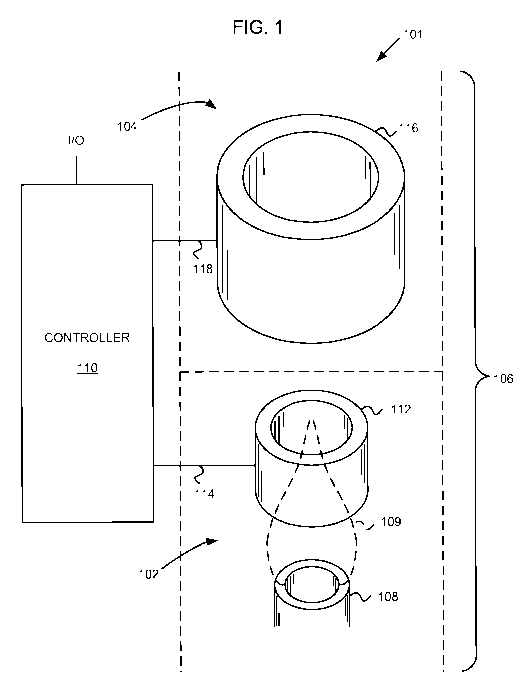
FIG. 1 is a diagram illustrating a combustion system 101 configured to select
two or more responses from respective portions 102, 104 of a heated volume 106
using electric fields, according to an embodiment.
A burner 108 disposed in a first portion 102 of the heated volume 106 may be
configured to support a flame 109. An electronic controller 110 is configured
to
produce at least a first and a second electrode drive signal. The first
portion 102 of
the heated volume 106 may include a substantially atmospheric pressure
combustion volume including one or more than one burner 108. The first and
second electric fields and the first and second portions 102, 104 of the
heated
volume 106 may be substantially non-overlapping. For example, the first and
second electric fields may be formed respectively in a boiler combustion
volume and
a flue. According to other embodiments, the first and second portions 102, 104
of
the heated volume 106 may overlap at least partially.
At least one first electrode 112 may be arranged proximate the flame 109
supported by the burner 108 and operatively coupled to the electronic
controller 110
to receive the first electrode drive signal via a first electrode drive signal
transmission
path 114. The first electrode drive signal may be configured to produce a
first
electric field configuration in at least the first portion 102 of the heated
volume 106.
The first electric field configuration may be selected to produce a first
response from
the system 101.
The at least one first electrode may include a range of physical
configurations.
For example, the burner 108 may be electrically isolated and driven to form
the at
least one first electrode. Additionally or alternatively, the at least one
first electrode
112 may include a torus or a cylinder as diagrammatically illustrated in FIG.
1.
According to another embodiment, the at least one first electrode 112 may
include a
charge rod such as a 1/4" outside diameter tube of Type 304 Stainless Steel
held
transverse or parallel to a flow region defined by the burner 108. One or more
second features (not shown) arranged relative to the at least one first
electrode may
optionally be held at a ground or a bias voltage with the first electric field
configuration being formed between the at least one first electrode and the
one or
more second features. Optionally, the at least one first electrode may include
at
3
CA 02826935 2013-08-08
WO 2012/109481 PCT/US2012/024541
least two first electrodes and the first electric field configuration may be
formed
between the at least two first electrodes.
Within constraints disclosed herein, an electric field configuration may
include
a static electric field, a pulsing electric field, a rotating electric field,
a multi-
axis/electric field, an AC electric field, a DC electric field, a periodic
electric field, a
non-periodic electric field, a repeating electric field, a random electric
field, or a
pseudo-random electric field.
At least one second electrode 116 may be arranged distal from the flame 109
supported by the burner 108 relative to the at least one first electrode 112.
The at
least one second electrode 116 may be operatively coupled to the electronic
controller 110 to receive the second electrode drive signal via a second
electrode
drive signal transmission path 118. The second electrode drive signal may be
configured to produce a second electric field configuration in the second
portion 104
of the heated volume 106. The second electric field configuration may be
selected to
produce a second response from the system 101.
The first response may be limited to a response that occurs in the first
portion
102 of the heated volume 106 and the second response may be limited to a
response that occurs in the second portion 104 of the heated volume 106. The
first
and second responses may be related to respective responses of first and
second
populations of ionic species present within the first and second portions 102,
104 of
the heated volume 106.
For example, the at least one first electrode 112 may be driven to produce a
first electric field in the first portion 102 of the heated volume 106
selected to drive
combustion within and around the flame 109 to a greater extent of reaction
compared to an extent of reaction reached with no electric field. For example,
the at
least one second electrode 116 may be driven to produce a second electric
field in
the second portion 104 of the heated volume 106 selected to drive greater heat
transfer from the heated volume compared to an amount of heat transfer reached
with no electric field.
FIG. 2 is a diagram illustrating a combustion system 201 configured to select
two or more responses from respective portions 102, 104 of a heated volume 106
using electric fields, according to another embodiment.
The system embodiments of FIGS. 1 and 2 may be configured such that at
least one of the first electrode and the second electrode includes at least
two
4
CA 02826935 2013-08-08
WO 2012/109481 PCT/US2012/024541
electrodes. For example, in the system 201 shown in FIG. 2, the electrode for
the
first portion 102 of the heated volume 106 may include a first electrode
portion 112a
configured as a ring electrode, and a second electrode portion 112b configured
as a
burner electrode. The electrode portions 112a, 112b may be driven by
respective
first electrode drive signal transmission paths 114a, 114b.
At least one first sensor 202 may be disposed to sense a condition proximate
the flame 109 supported by the burner 108. The first sensor(s) 202 may be
operatively coupled to the electronic controller via a first sensor signal
transmission
path 204. The first sensor(s) 202 may be configured to sense a combustion
parameter of the flame 109. For example, the first sensor(s) 202 may include
one or
more of a flame luminance sensor, a photo-sensor, an infrared sensor, a fuel
flow
sensor, a temperature sensor, a flue gas temperature sensor, an acoustic
sensor, a
CO sensor, an 02 sensor, a radio frequency sensor, and/or an airflow sensor.
At least one second sensor 206 may be disposed to sense a condition distal
from the flame 109 supported by the burner 108 and operatively coupled to the
electronic controller 110 via a second sensor signal transmission path 208.
The at
least one second sensor 206 may be disposed to sense a parameter corresponding
to a condition in the second portion 104 of the heated volume 106. For
example, for
an embodiment where the second portion 104 includes a pollution abatement
zone,
the second sensor may sense optical transmissivity corresponding to an amount
of
ash present in the second portion 104 of the heated volume 106. According to
various embodiments, the second sensor(s) 206 may include one or more of a
transmissivity sensor, a particulate sensor, a temperature sensor, an ion
sensor, a
surface coating sensor, an acoustic sensor, a CO sensor, an 02 sensor, and an
oxide of nitrogen sensor.
According to an embodiment, the second sensor 206 may be configured to
detect unburned fuel. The at least one second electrode 116 may be configured,
when driven, to force unburned fuel downward and back into the first portion
102 of
the heated volume 106. For example, unburned fuel may be positively charged.
When the second sensor 206 transmits a signal over the second sensor signal
transmission path 208 to the controller 110, the controller may drive the
second
electrode 116 to a positive state to repel the unburned fuel. Fluid flow
within the
heated volume 106 may be driven by electric field(s) formed by the at least
one
second electrode 116 and/or the at least one first electrode 112 to direct the
5
CA 02826935 2013-08-08
WO 2012/109481 PCT/US2012/024541
unburned fuel downward and into the first portion 102, where it may be further
oxidized by the flame 109, thereby improving fuel economy and reducing
emissions.
Optionally, the controller 110 may drive the first portion 112a of the at
least
one first electrode and/or the second portion 112b of the at least one first
electrode
to cooperate with the at least one second electrode 116. According to some
embodiments, such cooperation may drive the unburned fuel downward more
effectively than by the actions of the at least one second electrode 116
alone. For
example, a series of pulses to the electrodes 116, 112a, 112b may relay the
unburned fuel downward. A first portion of the relay may include the at least
one
second electrode 116 being driven positive while the first portion 112a of the
at least
first electrode is driven negative. Such a configuration may drive positively
charged
unburned fuel particles from the vicinity of the at least one second electrode
116 to
the vicinity of the first portion 112a of the at least one first electrode.
Then, as the
unburned fuel particles near the first portion 112a of the at least one first
electrode,
that portion 112a may be allowed to float, and the second portion 112b of the
at least
one first electrode may be driven negative, thus continuing the propulsion of
the fuel
particles downward and into the flame 109.
The controller 110 may include a communications interface 210 configured to
receive at least one input variable. FIG. 3 is a block diagram of an
illustrative
embodiment 301 of a controller 110. The controller 110 may drive the first
electrode
drive signal transmission paths 114a and 114b to produce the first electric
field
whose characteristics are selected to provide at least a first effect in the
first heated
volume portion 102. The controller may include a waveform generator 304. The
waveform generator 304 may be disposed internal to the controller 110 or may
be
located separately from the remainder of the controller 110. At least portions
of the
waveform generator 304 may alternatively be distributed over other components
of
the electronic controller 110 such as a microprocessor 306 and memory
circuitry
308. An optional sensor interface 310, communications interface 210, and
safety
interface 312 may be operatively coupled to the microprocessor 306 and memory
circuitry 308 via a computer bus 314.
Logic circuitry, such as the microprocessor 306 and memory circuitry 308 may
determine parameters for electrical pulses or waveforms to be transmitted to
the first
electrode(s) via the first electrode drive signal transmission path(s) 114a,
114b. The
first electrode(s) in turn produce the first electrical field. The parameters
for the
6
CA 02826935 2013-08-08
WO 2012/109481 PCT/US2012/024541
electrical pulses or waveforms may be written to a waveform buffer 316. The
contents of the waveform buffer may then be used by a pulse generator 318 to
generate low voltage signals 322a, 322b corresponding to electrical pulse
trains or
waveforms. For example, the microprocessor 306 and/or pulse generator 318 may
use direct digital synthesis to synthesize the low voltage signals.
Alternatively, the
microprocessor may write variable values corresponding to waveform primitives
to
the waveform buffer 316. The pulse generator 318 may include a first resource
operable to run an algorithm that combines the variable values into a digital
output
and a second resource that performs digital to analog conversion on the
digital
output.
One or more outputs are amplified by amplifier(s) 320a and 320b. The
amplified outputs are operatively coupled to the first electrode signal
transmission
path(s) 114a, 114b. The amplifier(s) may include programmable amplifiers. The
amplifier(s) may be programmed according to a factory setting, a field
setting, a
parameter received via the communications interface 210, one or more operator
controls and/or algorithmically. Additionally or alternatively, the amplifiers
320a,
320b may include one or more substantially constant gain stages, and the low
voltage signals 322a, 322b may be driven to variable amplitude. Alternatively,
output
may be fixed and the heated volume portions 102, 104 may be driven with
electrodes having variable gain.
The pulse trains or drive waveforms output on the electrode signal
transmission paths 114a, 114b may include a DC signal, an AC signal, a pulse
train,
a pulse width modulated signal, a pulse height modulated signal, a chopped
signal, a
digital signal, a discrete level signal, and/or an analog signal.
According to an embodiment, a feedback process within the controller 110, in
an external resource (such as a host computer or server) (not shown), in a
sensor
subsystem (not shown), or distributed across the controller 110, the external
resource, the sensor subsystem, and/or other cooperating circuits and programs
may control the first electrode(s) 112a, 112b and/or the second electrode(s)
116.
For example, the feedback process may provide variable amplitude or current
signals in the at least one first electrode signal transmission path 114a,
114b
responsive to a detected gain by the at least one first electrode or response
ratio
driven by the electric field.
7
CA 02826935 2013-08-08
WO 2012/109481 PCT/US2012/024541
The sensor interface 310 may receive or generate sensor data (not shown)
proportional (or inversely proportional, geometrical, integral, differential,
etc.) to a
measured condition in the first portion 102 of the heated volume 106.
The sensor interface 310 may receive first and second input variables from
respective sensors 202, 206 responsive to physical or chemical conditions in
the first
and second portions 102, 104 of the heated volume 106. The controller 110 may
perform feedback or feed forward control algorithms to determine one or more
parameters for the first and second drive pulse trains, the parameters being
expressed, for example, as values in the waveform buffer 316.
Optionally, as will be described more fully below, the controller 110 may
include a flow control signal interface 324. The flow control signal interface
may be
used to generate flow rate control signals to control fuel flow and/or air
flow through
the combustion system.
A flow chart showing a method 401 for maintaining one or more illustrative
relationships between the sensor data and the low voltage signal(s) 322a, 322b
is
shown in FIG. 4, according to an embodiment. For example, one or more
illustrative
relationships may include one or more programmable relationships.
In step 402, sensor data is received from the sensor interface 310. The
sensor data may be cached in a buffer or alternatively be written to the
memory
circuitry 308. One or more target values for the sensor data may be maintained
in a
portion of the memory circuitry 308 as a parameter array 404. Proceeding to
step
406, the received sensor data is compared to one or more corresponding values
in
the parameter array 404.
In step 408, at least one difference between the sensor data and the one or
more corresponding parameter values is input to a waveform selector, the
output of
which is loaded into the waveform buffer 316 in step 410.
According to some embodiments, at least one parameter of the first and
second electric fields may be interdependent. Thus, the parameter array may be
loaded with a plurality of multivariate functions of sensor vs. target values
and
electric field waveforms that are mutually determinate. For example, referring
to
FIG. 3, the controller 110 may receive at least one response value from the
heated
volume 106. The microprocessor 306 may calculate at least one first parameter
of
the first electric field responsive to the at least one response value and
calculate at
8
CA 02826935 2013-08-08
WO 2012/109481 PCT/US2012/024541
least one second parameter of the second electric field responsive to the at
least one
response value and the at least one first parameter.
In other embodiments, the first and second electric fields in the first and
second portions 102, 104 of the combustion volume 106 substantially do not
directly
interact. In such cases (and in some embodiments, in other cases), the
parameter
array 404 may include waveform parameters that are not mutually determinate.
Referring again to FIG. 4, the parameter array 404 may also include a fuel
flow rate and/or one or more waveform parameters that are selected and loaded
into
the parameter array 404 as a function of a fuel flow rate.
lo Step 408 may include determining a first electric field amplitude and/or
a first
electric field pulse width responsive to a fuel flow rate and determining at
least one of
a second electric field amplitude and a second electric field pulse width
responsive to
the at least one of a first electric field amplitude and a first electric
field pulse width.
The process 401 may be repeated, for example at a system tick interval.
The controller 110 may determine at least one parameter of at least one of the
first and second electric field drive signals responsive to the at least one
input
variable. For example, the at least one input variable may include one or more
of
fuel flow rate, electrical demand, steam demand, turbine demand, and/or fuel
type.
The controller 110 may further be configured to control a feed rate to the
burner 108. For example, referring to FIG. 5, the controller 110 may produce
an air
feed rate control signal on an air feed rate control signal transmission path
502 to
variably drive a fan or baffle, etc. 504. The burner may thereby receive more
or less
oxygen, which (other things being equal) may control the richness of the flame
109.
Similarly, the controller 110 may produce a fuel feed (rate, mix, etc.)
control signal on
a fuel feed control signal transmission path 506. The fuel feed control signal
transmission path 506 may couple the controller 110 to a control apparatus
508. For
example, the control apparatus 508 may include a valve to modulate fuel flow
rate to
the burner 108.
FIG. 5 also illustrates a combustion system 501 configured to produce at least
two electric fields in respective portions of a heated volume, according to an
embodiment wherein one of the portions includes a fuel delivery apparatus 510.
Strictly speaking, the fuel delivery apparatus 510 need not be in a literally
heated
portion 104 of the heated volume, but for ease of description, the heated
volume will
9
CA 02826935 2013-08-08
WO 2012/109481 PCT/US2012/024541
be understood to extend to a portion 104 corresponding to the fuel delivery
apparatus 510.
The fuel delivery apparatus 510 may be configured to receive an electric field
from one or more electrodes 512 coupled to receive corresponding electrode
drive
signals from the controller 110 via an electrode drive signal transmission
path 514.
The electric field produced across the fuel delivery apparatus 510 may be
driven to
"crack" or activate the fuel just prior to combustion. To reduce recombination
of the
fuel prior to exiting the burner 108, it may be advantageous to apply the fuel
delivery
apparatus electric field relatively close to the burner 108. For example, the
fuel
delivery apparatus 510 may include a ceramic burner body that feeds the burner
108. The one or more electrodes 512 may include conductors buried in the
ceramic
burner body, may include opposed plates having a normal line passing through
the
ceramic burner body, may include an electrode tip suspended in the fuel flow
path by
an assembly including a shielded electrode transmission path, may include an
annulus or cylinder, and/or may include a corona wire or grid, optionally in
the form
of a corotron or scorotron.
FIG. 6 is a diagram of a system using a plurality of controller portions 602,
604, 606, 620 to drive respective responses from portions 102, 104, 610, 618
of a
heated volume 106 in a combustion system 601, according to an embodiment. The
controller portions 602, 604, 606, 620 may be physically disposed within a
controller
110. Alternatively, the controller portions 602, 604, 606, 620 may be
distributed, for
example such that they are in proximity to their respective heated volume
portions
102, 104, 610, 618.
Some or all of the controller portions 602, 604, 606, 620 may include
substantially the relevant entirety of the controller 110 corresponding to the
block
diagram 301 of FIG. 3. Alternatively, referring to FIG. 3, portions of the
controller
function may be integrated in one or more shared resources, and other portions
of
the controller function may be distributed among the controller portions 602,
604,
606, 620. For example, according to an embodiment, each of the controller
portions
602, 604, 606, 620 may include a waveform generator 304, while the other
portions
of the controller 110 such as the microprocessor 306, memory circuitry 308,
sensor
interface 310, safety interface 312, bus 314, communications interface 210,
and the
flow control signal interface 324 are disposed in a common resource within the
controller 110.
CA 02826935 2013-08-08
WO 2012/109481 PCT/US2012/024541
Returning to FIG. 6, electrodes 112a, 112b, and 112c may be driven by
respective electrode drive signal transmission lines 114a, 114b, 114c by the
controller portion 602. The electrodes 112a, 112b, and 112c may be disposed to
form a modulated electric field in the first portion 102 of the heated volume
106
wherein a burner 108 supports a flame 109. The electric field may be driven to
provide swirl and/or otherwise accelerate combustion in and near the flame
109. At
least one response to the electric field generated by the electrodes 112a,
112b, and
112c may also be sensed by the electrodes 202a, 202b, 202c. The electric field
drive electrode 112a may thus also be referred to as an electric field sensor
202a.
Similarly electric field drive electrodes/sensors 112b, 202b and112c, 202c may
also
be used for both electric field driving and sensing. Similarly, at least
portions of the
electrode drive signal transmission paths 114a, 114b, 114c may also serve as
respective sensor signal transmission paths 204a, 204b, 204c.
A second controller portion 604 may drive an electrode 116 disposed in a
second portion 104 of the heated volume 106 via an electrode drive signal
transmission path 118. According to an embodiment, the electrode 116 may be
configured as the wall at a thermocouple junction 206 (not shown) configured
to
remove heat from the heated, and still ionized, gases exiting the first
portion 102 of
the heated volume 106. A sensor signal transmission path 208 may couple to a
portion of the heat exchanger wall at a thermocouple junction 206 (not shown).
Feedback from the sensor signal transmission path 118 may be used, for
example,
to control a water flow rate into the heat exchanger and/or control gas flow
to the
flame 109.
Thus, the combustion system 601 may provide functionality for a variable-
output boiler, configured to heat at a variable rate according to demand. Of
course,
the burner 108 may include a plurality of burners with fuel flow being
provided to a
number of burners 108 appropriate to meet continuous and/or surge demand.
A third controller portion 606 may drive electrodes 608a, 608b, 608c, 608d
disposed in a third portion 610 of the heated volume 106. The third controller
portion
606 may drive the electrodes 608a, 608b, 608c, 608d through respective
electrode
drive signal transmission paths 612a, 612b, 612c, 612d. The electrodes 608a,
608b,
608c, 608d may be configured as electrostatic precipitation plates operable to
trap
ash, dust, and/or other undesirable stack gas components from the gases
passing
through the heated volume portion 610.
11
CA 02826935 2013-08-08
WO 2012/109481 PCT/US2012/024541
Optionally, a sensor 614 may transmit a sensor signal through a sensor signal
transmission path 616 to the controller portion 606. The sensor 614 may be
configured to sense a condition indicative of a need to recycle gases from the
heated
volume portion 610 back to the first heated volume portion 102 for further
heating
and combustion. For example, the sensor 614 may include a spectrometer
configured to detect the presence of unburned fuel in the heated volume
portion 610.
Upon receiving a signal from the sensor 614 via the sensor signal
transmission path 616, the controller portion 606 may momentarily set the
polarity of
the electrodes 608a, 608b, 608c, 608d to drive ionic species present in the
heated
volume portion 610 downward and back into the vicinity of the flame 109. Gases
and uncharged fuel particles present in the gases within the heated volume
portion
610 may be entrained with the ionic species. Alternatively, substantially all
the fuel
particles within the heated volume portion 610 may retain charge and be driven
directly by the electric field provided by the electrodes 608a, 608b, 608c,
608d.
A fourth portion 618 of the heated volume 106, which as described above may
be considered a heated volume portion by convention used herein rather than
literally heated, may correspond to a fuel feed apparatus 510. A controller
portion
620 may drive an electrode 512, disposed proximate the fuel feed apparatus
510, via
an electrode drive signal transmission path 514 to activate the fuel, as
described
above in conjunction with FIG. 5.
A fuel ionization detector 622 may be disposed to sense a degree of
ionization of the fuel flowing from the fuel delivery apparatus 510 to the
burner 108
and flame 109, and transmit a corresponding sensor signal to the controller
portion
620 via a sensor signal transmission path 624. The sensed signal may be used
to
select an amplitude, frequency, and/or other waveform characteristics
delivered to
the electrode 512 from the controller portion 620 via the electrode drive
signal
transmission path 514.
Those skilled in the art will appreciate that the foregoing specific exemplary
processes and/or devices and/or technologies are representative of more
general
processes and/or devices and/or technologies taught elsewhere herein, such as
in
the claims filed herewith and/or elsewhere in the present application.
While various aspects and embodiments have been disclosed herein, other
aspects and embodiments are contemplated. The various aspects and
12
CA 02826935 2013-08-08
WO 2012/109481 PCT/US2012/024541
embodiments disclosed herein are for purposes of illustration and are not
intended to
be limiting, with the true scope and spirit being indicated by the following
claims.
13