Note : Les descriptions sont présentées dans la langue officielle dans laquelle elles ont été soumises.
CA 02827190 2013-08-12
WO 2011/100461 PCT/US2011/024389
APPARATUS FOR ADJUSTING FOOT STRUCTURES, FOR DESIGN OF A FOOT
ORTHOTIC, AND METHODS OF USE
CROSS-REFERENCE TO RELATED APPLICATIONS
[001] This application claims the benefit of U.S. provisional application
serial
no. 61/303,554, filed February 11, 2010, incorporated by reference herein.
TECHNICAL FIELD
[002] The subject matter described herein relates to an apparatus for
adjusting a structure, such as a bone, in a foot, and for design of a foot
orthatic with
the foot structures in an adjusted state. More particularly, the subject
matter is
directed to an apparatus that adjusts structures, e.g., bones and soft tissue,
of a foot
to a desirable corrective position or alignment, and provides a graphic image
of a
surface contour of a corrective orthotic device that maintains the desirable
corrective
position or alignment of the foot structures.
BACKGROUND
[003] There are two basic types of custom foot orthoses made today,
accommodative orthoses and functional orthoses. An accommodative orthosis is
typically made from a soft or flexible material that cushions and
"accommodates" any
deformity of the foot. This cushioning also results in some dissipation of the
forces
required for efficient gait that ordinarily would be transmitted up the
kinetic chain.
Accommodative orthosis, which are typically made of soft or cushioning
materials, are
unable to control foot mechanics.
[004] A functional foot orthosis is one that controls joint movements
and/or foot
position. Functional foot orthoses are typically rigid, and clinicians utilize
them to hold
the foot in a position deemed corrective or therapeutic. This approach is
problematic
because the foot must be allowed to remain mobile to continually adapt to the
ground in
order to operate efficiently.
[005] Foot orthotics are typically designed based on an exact contour or
image
of the plantar surface of a patient's foot, and there are a variety of
instruments and
systems for obtaining the exact contour, including mechanical approaches, such
as
impression molds using plaster, sand, or foam, and electronic approaches, such
as
electro-mechanical and electro-optical devices. The available approaches
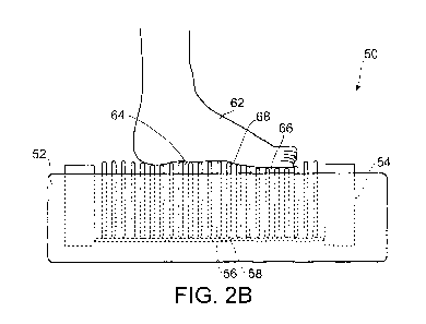
generally
CA 0/817190 1013-08-11
WO 2011/100461 PCT/US2011/024389
provide a mechanical or digital representation of the sensed contour or
topography of
the foot, absent any individualized, restorative adjustment of foot structures
(e.g.,
bones or soft tissues). While functional and accommodative orthotics may
temporarily
decrease foot pain due to restricting pathologic range of motion and in
cushioning the
foot, they necessarily cause pathologic gait, and this approach will
inevitably cause pain
in other joints in the foot, leg, pelvis and/or back as they compensate for
this abnormal
motion. There remains a need for an apparatus that generates an image or
contour of
a foot's plantar surface when the foot's structures are adjusted to a restored
position,
from which a foot orthosis can be constructed that corrects and/or restores
the alignment
and/or positioning of foot structures.
[006] The foregoing examples of the related art and limitations related
therewith
are intended to be illustrative and not exclusive. Other limitations of the
related art will
become apparent to those of skill in the art upon a reading of the
specification and a
study of the drawings.
BRIEF SUMMARY
[007] The following aspects and embodiments thereof described and
illustrated below are meant to be exemplary and illustrative, not limiting in
scope.
[008] In a first aspect, an apparatus comprising a plurality of engagement
structures and one or more biasing members is provided. Each pin is
independently
movable along a longitudinal axis, and the one or more biasing members is
configured
to exert a force on one or more pins in the plurality of pins, such that a
first set of pins
in the plurality of pins moves from a first position to a second position
independent of a
second set of pins in the plurality of pins.
[009] In one embodiment, the one or more biasing members exerts a force to
achieve movement of the one or more pins in the plurality of pins. In another
embodiment, the one or more biasing members resists a force applied to one or
more
pins in the plurality of pins.
[010] In one embodiment, pins in the first set of pins are moved prior to
movement of pins in the second set of pins. In another embodiment, pins in the
first
set of pins are moved by a first force applied by a biasing member in the one
or more
biasing members to the pins in the first set of pins, the first force
different from a
second force applied by a biasing member in the one or more biasing members to
pins in the second set of pins.
[011] In another embodiment, the one or more biasing members comprise at
CA 02827190 2013-08-12
WO 2011/100461 PCT/US2011/024389
least two biasing members.
[012] In yet another embodiment, a first biasing member is dedicated to
achieve movement of the first set of pins and a second biasing member is
dedicated
to achieve movement of the second set of pins.
[013] In other embodiments, the one or more biasing members comprise a
plurality of biasing members, for example, the plurality comprises 2, 3, 4, 5,
6, 7, 8, 9,
10, 11 or more biasing members. In other embodiments, each biasing member is
dedicated for achieving movement of a single pin in the plurality of pins or
of a single
set of pins in the plurality of pins.
[014] In one embodiment, the one or more biasing members are comprised of
a pressurized fluid. In yet another embodiment, a first biasing member exerts
a first
pressure on pins in the first set of pins to move the pins in the first set of
pins along
their longitudinal axes, and a second biasing member exerts a second pressure
on
pins in the second set of pins to move the pins in the first set of pins along
their
longitudinal axes, where the first pressure is different that the second
pressure. In
one embodiment, the first pressure is higher than the second pressure.
[015] In still other embodiments, the one or more biasing members is
configured for contact with a third set of pins in the plurality of pins such
that pins in
the third set move along their longitudinal axis independent from pins in the
first set of
pins or the second set of pins.
[016] In one embodiment, the third set of pins are moved subsequent to
movement of pins in the first set of pins, and in another embodiment, the
third set of
pins are moved by a pressure applied to the third set of pins that is
different from a
pressure applied to the first set of pins. In another embodiment, the third
set of pins
are moved at a time and at a pressure different from the first and/or second
set(s) of
pins. Similarly, in some embodiments, the second set of pins are moved at a
pressure
different from the first set of pins, at a time different from the first set
of pins, or both.
[017] in some embodiments, the first set of pins is within a center region
of
the plurality of pins and the second set of pins surround the periphery of the
center
region, or in other words, are in a non-center regions of the plurality of
pins.
[018] The plurality of pins collectively define an upper surface and a
lower
surface, and in one embodiment, the one or more biasing members is a single,
movable biasing member that contacts the lower surface of the plurality of
pins.
[019] In yet other embodiments, the apparatus further comprises a sensor to
determine a position of one or more pins within the plurality of pins.
3
CA 02827190 2013-08-12
WO 2011/100461 PCT/US2011/024389
[020] In another aspect, an apparatus comprised of a plurality of pins and
at
least one biasing member is provided, wherein the plurality of pins is
supported with a
frame or housing, and each pin is independently movable along a longitudinal
axis.
One or more biasing members is disposed within the frame, where the one or
more
biasing members is configured for contact with one or more pins in the
plurality of pins
such that a first set of pins in the plurality of pins is moved along the
longitudinal axis
of each pin in the first set at a pressure and/or at a time different from
movement of a
second set of pins in the plurality of pins along the longitudinal axis of
each pin in the
second set.
[021] In one embodiment, the one or more biasing members comprise a
plurality of biasing members. In another embodiment, each biasing member in
the
plurality of biasing members is dedicated for movement of a single pin in the
plurality
of pins or of a single set of pins in the plurality of pins.
[022] in another embodiment, a first biasing member is dedicated for urging
pins in the first set of pins from a first position to a second position
(e.g., from an initial
position to an engagement position), and a second biasing member is dedicated
for
urging pins in the second set of pins from a first position to a second
position (e.g.,
from an initial position to an engagement position).
[023] In another embodiment, the one or more biasing members is configured
for direct or indirect contact with sets of pins, and in another embodiment,
for direct or
indirect contact with a third set of pins in the plurality of pins such that
pins in the third
set move along their longitudinal axis at a pressure or at a time (e.g,
subsequent to)
different than pins in the first set of pins and/or the second set of pins.
[024] In another embodiment, the biasing member has an upper surface for
contact with the lower surface of the plurality of pins, and wherein the upper
surface of
the biasing member has a pre-selected contour to contact the first set of pins
prior to
contact with the second set of pins. In a more specific embodiment, the
biasing
member is rectangular, and the upper surface has a pyramid-like contour with
an apex
offset from a center point of the rectangle. In another specific embodiment,
the
biasing member is rectangular, and the upper surface has a terraced contour
with an
uppermost terrace offset from a center point of the rectangle. In yet another
specific
embodiment, the biasing member consists of tens sides, and wherein five of the
ten
sides are on the upper surface. In yet another specific embodiment, the pre-
selected
contour of the biasing member is a pyramid-like shape with a flat apex.
[025] in another embodiment, the biasing member is composed of a first
4
CA 02827190 2013-08-12
WO 2011/100461 PCT/US2011/024389
material having a first density and a second material having a second density.
In
another embodiment, the biasing member or members is/are composed of a fluid,
preferably a gas, that can be pressurized to urge pins from first to second
positions.
In other embodiments, the biasing member or members is/are a force that act
directly
or indirectly on one or more pins to effect movement of the pin(s) from first
to second
positions. Exemplary forces include magnetic force, a pneumatic force or
pressure, a
pressurized fluid force, gravitational force, a mechanical force and the like.
[026] In another embodiment, the biasing member is composed of a first
material having a first durometer and a second material having a second
durometer.
In a specific embodiment, the first material is a viscoelastic foam. In other
specific
embodiments, the biasing member is composed of a rubber, an elastomer, a
plastic,
or a foam.
[027] In yet another embodiment, the apparatus further comprises a locking
member to secure one or more pins in the plurality of pins.
[028] In still another embodiment, the apparatus further comprises a sensor
to
determine a position of one or more pins within the plurality of pins. In a
specific
embodiment, the apparatus comprises a single sensor that determines the
position of
each pin in the plurality. In another specific embodiment, the apparatus
comprises two
or more sensors. In various specific embodiments, the sensor is a non-contact
sensor
and exemplary non-contact sensors include a laser, such as a one-dimensional
laser,
a two-dimensional laser, or a three-dimensional laser, and an optical distance
scanner. The apparatus can optionally include a reflective surface positioned
to
reflect a beam from a laser sensor. In yet another specific embodiment, the
sensor
comprises a plurality of cameras for obtaining images of the plurality of pins
from a
plurality of angles.
[029] In another embodiment, each pin in the plurality of pins has a
diameter
between 0.0624 inches to 0.250 inches.
[030] In still another embodiment, the apparatus further comprises a
transducer, such as a hall sensor or capacitive sensor, associated with the
one or
more biasing members.
[031] In yet another embodiment, the apparatus comprises a sensor to
determine relative movement of the one or more biasing members.
[032] In still another embodiment, the plurality of pins and the one or
more
biasing members are capable of producing a force per pin of between about 0.02-
4.0
lb-f, more preferably between about 0.02-.5 lb-f.
CA 0/817190 1013-08-11
WO 2011/100461 PCT/US2011/024389
[033] In another aspect, a method for obtaining a restored bone state in a
foot
and/or for constructing a foot orthotic is provided. The method comprises
placing a
plantar surface of a foot on an apparatus as described herein, the plantar
surface
placed on an upper surface defined by the plurality of pins, wherein said
plurality of
pins are in an initial position. Movement of pins in the plurality of pins is
initiated, via
the one or more biasing members, such that a first set of pins adjusts one or
more
bones in the foot to a restored bone state and a second set of pins engages
the foot
plantar surface with the foot in its restored bone state. A position of each
pin in at
least the first pin set and the second pin set is determined, to obtain a
profile of the
foot in its restored bone state, from which an orthotic for the foot can be
constructed.
[034] In one embodiment, the method further comprises transferring
positional
information of each pin to a computer. In another embodiment, a position of
each pin
in at least the first pin set and the second pin set is determined, to obtain
a profile for
construction of a foot orthotic or a series of foot orthotics to be worn
sequentially.
[035] In yet another embodiment, the first set of pins adjusts one or more
bones in the mid-foot region, or localized mid-foot region, of the foot, and a
third set of
pins in the plurality of pins moves via the one or more biasing members, such
that pins
in the third set of pins engage the foot plantar surface at a region other
than the mid-
foot region.
[036] In yet another aspect, a method is provided, wherein the method
comprises placing a plantar surface of a foot an apparatus comprising (i) a
plurality of
pins, wherein each pin in the plurality of pins is independently movable along
a
longitudinal axis, and (ii) one or more biasing members configured for contact
with one
or more pins in the plurality of pins, such that a first set of pins in the
plurality of pins is
moved along the longitudinal axis of each pin in the first set independent of
a second
set of pins in the plurality of pins. Movement of the one or more biasing
members is
effected, such that the first set of pins adjusts one or more bones in the
foot to an
adjusted position; and a position of each pin in at least the first pin set
and the second
pin set is determined.
[037] In one embodiment, the first set of pins adjusts one or more bones in
the foot to a restored bone position. In another embodiment, the first and
second sets
of pins engage the foot in order to achieve a restored bone position.
[038] In one embodiment, movement of the pins or a biasing member is such
that the first set of pins adjusts one or more mid-foot bones to an adjusted
position.
6
CA 0/817190 1013-08-11
WO 2011/100461 PCT/US2011/024389
[039] In another embodiment, the one or more biasing members is a fluid,
and
pressurizing the fluid effects movements of one or more pins or sets of pins
in the
plurality.
[040] In another embodiment, a first biasing member has a first pressure,
to
achieve movement of the first pin set, and a second biasing member has a
second
pressure, to achieve movement of the second pin set. The first pressure and
the
second pressure can be the same or different.
[041] In other embodiments, the position of an end of each pin in at least
the
first pin set and the second pin set that engages the foot plantar surface are
determined, to obtain a positional point of each pin, the positional points
collectively
defining a surface map.
[042] In one embodiment, the method further comprises after the step of
causing, locking the plurality of pins to secure each pin in a final position.
[043] In another embodiment, the step of determining comprises determining
by means of the sensor a position of each pin.
[044] In still another embodiment, the method further comprises
transferring
positional information of each pin to a computer to construct a digital image
of the
profile.
[045] In another embodiment, the step of determining comprises determining
a position of each pin in at least the first pin set and the second pin set to
obtain a
profile for construction of a series of foot orthatics to be worn
sequentially.
[046] In another aspect, a method comprises providing an apparatus
comprising (i) a plurality of pins, wherein each pin in the plurality of pins
is
independently movable along a longitudinal axis, and (ii) one or more biasing
members configured for contact with one or more pins in said plurality of pins
such
that a first set of pins in the plurality of pins is moved along the
longitudinal axis of
each pin in the first set independent (e.g., prior to or at a different
pressure) movement
of a second set of pins in said plurality of pins along the longitudinal axis
of each pin in
the second set of pins: placing a plantar surface of a foot on the plurality
of pins;
causing movement of the one or more biasing members such that some of all of
the
pins in the first set of pins adjusts one or more bones in the foot to an
adjusted
position, and the second set of pins engages the foot plantar surface at
positions
responsive to the one or more bones in the adjusted position; and after the
step of
causing, determining a position of each pin in at least the first pin set and
the second
pin set.
7
CA 02827190 201308-12
WO 2011/100461 PCT/US2011/024389
[047] In another embodiment, the first set of plurality of pins contacts a
foot
plantar surface in a pre-determined or pre--selected force, contour or pattern
to
produce mid-tarsal movement sufficient to produce tension in a dorsal ligament
thereby producing an adjusted position of the foot. Second and subsequent sets
of
pins in the plurality are contact the foot in its adjusted position, the
second and
subsequent plurality of pins contacting the foot in its adjusted bone position
or
restored bone state at a time or force different or the same as the first pin
set.
[048] In another aspect, a method is provided, wherein the method comprises
engaging a center engagement structure against a localized mid-foot region of
a
plantar surface of a subject's foot to adjust one or more mid-foot bones into
a restored
bone state; engaging one or more peripheral engagement structures against a
region
other than the mid-foot region to contact the plantar surface while
maintaining the
engagement of the center structure; obtaining positional information of the
engagement structures; and based on the positional information, determining a
surface map or orthotic profile.
[049] In addition to the exemplary aspects and embodiments described
above, further aspects and embodiments will become apparent by reference to
the
drawings and by study of the following descriptions.
BRIEF DESCRIPTION OF THE DRAWINGS
[050] FIGS. 1A-1B are views of an individual's right foot, shown as a top
plan
view (FIG. 1A) and a side view from the right (FIG. 1B);
[051] FIGS. 1C-1E are a top plan views of a right foot, showing the 1St,
and 5m rays (Fig. 1C), the mid-foot region and the localized mid-foot region
(Fig. 1E).
[052] FIGS. 2A-2B is a perspective view (FIG. 2A) and a side view (FIG. 29)
of an embodiment of the apparatus described herein;
[053] FIGS. 3A-3B are simplified illustrations of an embodiment of the
apparatus, where a biasing member provides differential movement of pins in a
plurality of pins, where the pins in an initial resting position (FIG. 3A) are
urged along
their longitudinal axes by a contoured biasing member (FIG. 39);
[054] FIG. 4 is a illustration of another embodiment of a biasing member
having a preselected surface contour to provide differential movement of pins
in a pin
bed array;
[055) FIG. 5 is a top view of a pin bed showing a center band region of
pins:
[056] FIGS. 6A-6B are simplified illustrations of another embodiment of
the
8
CA 02817190 1013-08-11
WO 2011/100461 PCT/US2011/024389
apparatus, where a biasing member provides differential movement of pins in a
plurality of pins, where the pins in an initial resting position (FIG. 6A) are
urged along
their longitudinal axes upon inflation of a biasing member (FIG. 6B);
[057] FIGS. 7A-7C are simplified illustrations of another embodiment of the
apparatus, wherein differential, independent movement of each pin in a
plurality of
pins is achieved by individual electronics assigned to each pin, where the
pins in an
initial resting position (FIG. 7A) are urged along their longitudinal axes
upon activation
or electronic signaling (FIGS. 78-70);
[058] FIG. 8 illustrates another embodiment wherein differential,
independent
movement of pins, or engagement structures, is achieved by a spring associated
with
each pin;
[059] FIGS. 9A-9C are simplified illustrations of another embodiment of the
apparatus, wherein differential, independent movement of sets of pins is
achieved
pneumatically via pressurized fluid as the biasing member, where the pins in
an initial
resting position (FIG. 9A) are moved in sets in response to pressure in a zone
in fluid
communication with each set (FIGS. 98-90);
[060] FIGS. 10A-10B illustrate in top view (FIG. 10A) and in cross-
sectional
view (FIG. 10B) another embodiment of an array of engagement structures that
engages a localized mid-foot region of a foot plantar surface to manipulate
bones into
an adjusted or restored state, with subsequent engagement by peripheral
engagement
structures of regions surrounding the mid-foot region;
[061] FIG. 11A is a perspective view of another embodiment, comprising a
pin
bed array and a biasing member associated with each pin or with zones of pins
in the
array to permit differential, independent movement of the pins or zones of
pins along
their longitudinal axes;
[062] FIG. 11B is a perspective view of another embodiment comprising a pin
bed array and a biasing member that provides differential, independent
movement of
the pins along their longitudinal axes in accord with the surface contour of
the biasing
member;
[063] FIGS. 12A-12C illustrate in sequence operation of an exemplary
apparatus, where pins are in initial resting positions (FIG. 12A), a zone of
pressurized
gas acts as a biasing member to effect movement of pins or pin sets in a
desired
pattern or sequence of movement (FIG. 128), and the position of each pin or
pin set is
ascertained (FIG. 12C); and
[064] FIGS. 13A-130 illustrate in sequence operation of another exemplary
9
CA 0/817190 1013-08-11
WO 2011/100461 PCT/US2011/024389
apparatus, where the pins are in initial resting positions and the biasing
member is
retracted (FIG. 13A), the biasing member is moved into position to urge the
pins
upward (FIG. 138), and the position of each pin is ascertained (FIG. 13C).
DETAILED DESCRIPTION
I. Definitions
[065] As used throughout the present disclosure, the technical and
scientific
terms used in the descriptions herein will have the meanings commonly
understood by
one of ordinary skill in the art, unless specifically defined otherwise.
[068] As used in this specification and the appended claims, the
singular forms
"a," "an," and "the" include plural referents unless the context clearly
indicates otherwise.
Thus, for example, reference to a patient's "foot" can include both feet,
reference to an
"orthotic device" includes a single device as well as two or more of the same
or different
devices, and reference to a "tarsal bone" refers to a single tarsal bone as
well as two or
more tarsal bones. The use of "or" should be understood to mean "and1or"
unless stated
otherwise. Similarly, "comprise," "comprises," "comprising" "include,"
"includes,"
"including," "has," "have" and "having" are interchangeable and not intended
to be
limiting. It is also to be understood that where descriptions of various
embodiments use
the term "comprising," those skilled in the art would understand that in some
specific
instances, an embodiment can be alternatively described using language
"consisting
essentially of or "consisting of."
Apparatus
[067] Before discussing the subject apparatus and its methods of use, a
brief
anatomy of the foot is provided, with reference to FIGS. 1A-1B which depict
bones and
joints in a right foot and lower leg 10. As seen in FIG. 1A, the phalanges 12
form the
toes and connect to the metatarsals 16. Together, the five phalanges and the
five
metatarsals form the "forefoot". As a point of reference, the first metatarsal
bone is
commonly known as the 'big toe' and typically bears the most weight in the
forefoot and
plays a role in propulsion. The "mid-foot" region 14 includes the three
cuneiform bones,
lateral, middle and medial, generally designated at 18, the cuboid bone 20 and
the
navicular bone 22. The distal row of the midfoot contains the three cuneiforms
and the
cuboid and is bounded distally by the metatarsal bones. The proximal row of
the midfoot
consists of the cuboid and the navicular. The three cuneiforms articulate
proximally with
the navicular bone. The "rear foot" 24 includes the talus 26 and the calcaneus
28. The
o
CA 02817190 1013-08-11
WO 2011/100461 PCT/US2011/024389
calcaneus is the largest tarsal bone, and forms the heel. The talus rests on
top of the
calcaneus, which interconnects the foot to the tibia 30 and the fibula 32. A
subtalar joint
34 constitutes the interface between the talus 26 and the calcaneus 28. A
midtarsal joint
36 comprises the interface between cuboid bone 20, navicular bone 25, talus
bone 26
and calcaneus bone 28.
[068] The foot is typically divided into two columns. As shown in FIG. 1A,
a
lateral or lateral load-bearing column is generally designated by identifier
38, which is to
the right of dashed line 37. Lateral load-bearing column 38 comprises the
calcaneus 28,
the cuboid 20 and the fourth and fifth rays of the metatarsals 16 and of the
phalanges 12.
This represents the outer portion of the foot including the fourth and fifth
toes. A medial
or medial dynamic column generally designated by identifier 40, which it to
the left of
dashed line 37, comprises the talus 26, the navicular 22, the cuneiforms 18
and rays
one, two and three of the metatarsals and of the phalanges. This corresponds
to the
inner section of the foot including the first three toes.
[069] There are four arches of the foot. The "medial longitudinal arch"
includes
the calcaneus, talus, navicular, the lateral, middle and medial cuneiforms,
and the first
three metatarsals. In an ideal foot, the medial longitudinal arch is the
highest of the three
arches. The "lateral longitudinal arch" includes the calcaneus, cuboid, and
the fourth and
fifth metatarsals. The lateral longitudinal arch is typically lower and
flatter than the
medial arch. The two transverse arches are the "transverse tarsal arch"
(comprising the
cuneiforms, the cuboid and the base of the five metatarsals) and the
"transverse
metatarsal arch" (comprising the 5 metatarsal heads).
[070] As will be detailed below, the present apparatus when in contact with
a
plantar surface of a foot adjusts selected foot structures, e.g., bones,
joints, soft tissues.
preferably initially in the midfoot region and subsequently in regions
surrounding the mid
-
foot region. Adjustment of foot structures in a mid-foot region initially
places the foot in a
restored or adjusted state, wherein the relationship between the foot bones is
clinically
optimal. As used herein, an "initial bone state" intends the relationships of
the bones in
a patient's foot in a first, initial or unrestored configuration/relationship
before
adjustment or manipulation of the bones, such as by treatment with an
apparatus as
described herein. A "restored bone state" refers to the
configuration/relationship of
foot bones that is different from an initial bone state, and in a preferred
embodiment
refers to the configuration/relationship of foot bones that approaches or is a
physiologically or medically desired position, for example, for optimal joint
congruency
and function. The apparatus includes structures for constructing an image or
'digital
CA 02817190 1013-08-11
WO 2011/100461 PCT/US2011/024389
orthotic profile' that is used in construction of a foot orthotic device to
maintain the foot
bones in its restored bone state; that is with foot structures in a clinically
optimal position.
Neither the midtarsal joint nor the subtalar joint is a guiding or controlling
structure, but
instead these joints are merely responsive to the position of other foot
structures, in
particular structures in the mid-foot.
[071] Figs. 1C-1E illustrate what is intended by the term mid-foot region.
Fig.
shows the is', 2nd and 5th rays of foot 10, designed as 42, 43, and 44,
respectively.
The 1 st ray is along dashed line 42 and extends from the phlanges of the big
toe, along
the first metatarsal, bisects the lateral cunieform and the naviculan The 2nd
ray is along
dashed line 43, and extends from the phlanges of the second toe, the second
metatarsal, bisects the medial cunieform and the navicular. The 5th ray is
along dashed
line 44 and extends along the fifth or little toe phlanges, the 5tt'
metatarsal, and the lateral
edge of the cuboid bone. The mid-foot in a preferred embodiment is the region
denoted
46 in Fig. 1D and bounded by the 1st and 5th rays, the base of the metatarsals
and the
midtarsal joint. The "localized" mid-foot region is the region denoted 48 in
Fig. 1E and is
bounded by the 2nd and 51h rays, the base of the metatarsals and the midtarsal
joint.
[072] Turning now to the subject apparatus, a first embodiment is shown in
Figs.
2A-2B. Apparatus 50 is generally comprised of a housing 52 enclosing a support
frame
54, the top portion of which is visible in Figs. 2A-2B, and shown more fully
in phantom in
Fig. 2B. Disposed within support frame 52 is a plurality of movable pins or
engagement
structures, such as pins 56, 58 which are representative, to form a pin bed
60. Each pin
is moveable between at least a first position and a second position, and is
optionally
movable to subsequent positions if desired. In one embodiment, a first pin
position is a
resting position in which the pin is withdrawn from contact with a foot 62
placed on the
pin bed, and a second pin position is an engagement position in which the pin
is in
contact with the plantar surface 64 of the foot. In other embodiments, a first
position is a
resting position wherein a pin is in contact with a foot placed on the pin bed
in such a
way that little or no force is exerted by the pin against the plantar surface
of the foot, and
a second position is an engagement position in which the pin exerts a pressure
or force
on the plantar surface of the foot. An optional support plate 66 has a
plurality of
openings, such as openings 68, 70, through which a single pin can move as it
travels
betweens its resting position and its engagement position. The apparatus will
generally,
but optionally, include input and output ports, such as ports 72, 74, for
connecting the
apparatus to peripheral equipment, such as keyboards, computers, and other
electronics. Appropriate on/off electronics 76 and display lights can
optionally be
12
CA 02827190 2013-08-12
WO 2011/100461 PCT/US2011/024389
included.
[073] The apparatus also includes a biasing member, not shown in Figs. 2A-
2B, but shown and described with reference to Figs. 3-9. As will be evident
from the
description of Figs. 3-9, the apparatus can include one or more biasing
members, and
a variety of biasing members are contemplated, the embodiments shown herein
merely exemplary of the concept. In a first embodiment, shown in Figs. 3A-3B,
a
frame 80 provides structural support for an array of pins 82 and a biasing
member 84.
Biasing member 84 is positioned on a platform 86, visible in Fig. 3B, which is
movable
by a drive means 88.
[074] Biasing member 84 has an upper surface 90 that has a preselected
contour. The contour in the embodiment of Figs. 3A-3B is such that an inner
region
92 of the surface is a flat apex, relative to the upper surface 90. Regions of
surface 90
surrounding the apex gently slope, giving the surface of the biasing member a
pyramid-like contour. The biasing member is movable between a first position,
as
depicted in Fig. 3A, and a second position, as depicted in Fig. 3B. The
biasing
member in its first position is positioned such that its upper surface is not
in contact
with pins in the array or, alternatively, touches the proximal ends of
selected pins
correspondingly disposed above the flat apex region. As the biasing member
travels
from its first position to its second position, pins in the array of pins are
engaged and
displaced, in a pattern dictated by the preselected contour of the upper
surface of the
biasing member. In this embodiment, a first set of pins, designated by the
bracket 94,
is first contacted by the flat apex region of the biasing member. First set of
pins 94
moves along their respective longitudinal axes, such as axis 96 of pin 98.
Continued
upward (with respect to the drawing) movement of the biasing member brings
contact
between the regions of the biasing member surface surrounding the apex and a
second set of pins, designated by brackets 100, 102. Pins in the second set,
once in
engaging contact with the biasing member, move along their longitudinal axes.
It is
appreciated that as the biasing member continues movement, third, forth, and
additional sets of pins come into contact with the biasing member and are
urged into
motion, for contact with a plantar surface of a foot on the array of pins. It
is also
appreciated that second and subsequent sets of pins are peripheral to the
first set of
pins, and preferably peripheral annularly. The number of pins in a set will
vary, as can
be appreciated, and can range from 1 pin to n-1 pins, where n is the total
number of
pins in the pin bed. More generally, the number of pins in a set will range
from 3-10%
of n, from 5-20% of n, from 8-25% of n, and from 10-30% of n, or in other
I 3
CA 02827190 2013-08-12
WO 2011/100461 PCT/US2011/024389
embodiments, from 3-30% of n.. As will be illustrated below, the number of
pins in a
set is not critical to the invention so long as the movement of the pin sets
encounters
and interacts with a foot to achieve movement of a foot structure from a first
initial
bone state to a second restored bone state. In preferred embodiments, a foot
structure in the mid-foot region of the foot is adjusted to a restored bone
state, and in
more preferred embodiments, a foot structure in the mid-foot region of the
foot is
adjusted to a restored bone state prior to adjustment of a foot structure in a
non-mid-
foot region.
[075] A skilled artisan will appreciate that the contour of the biasing
member
determines the initiation of movement of each pin in the array of pins, and
the final
position of each pin in the array. A variety of geometric shapes and surface
contours
of the biasing member are envisioned and contemplated. The pyramid-like shape
is
merely exemplary, and an alternative shape or surface contour is a terrace
shape.
Another exemplary shape is shown in Fig. 4, where member 104 has a surface
contour that includes a raised structure 105. Structure 105 has an apex 106
that will
engage one or more movable pins in a first set of an array of pins prior to
engagement
of pins peripheral to the first set. The apex of the biasing member is
positioned within
the apparatus such that a foot placed on the pin bed array is initially
engaged by the
first set of pins, i.e., the pins engaged by the apex 106 of structure 105, in
a mid-foot
region. Raised structure 105 has one or more slopes, such as slopes 107a,
107b,
107c. and 107d, that extend from the base surface 108 of biasing member 104 to
apex 106. A skilled artisan will appreciate the possible variations in the
actual
dimensions of each slope, and the sidewalls between each slope.
[076] Generally, and in a preferred embodiment, the surface contour of the
biasing member causes initial movement of a first set of pins in an inner
region of the
pin array. To illustrate, Fig. 5 depicts a top view of an array of pins 110. A
first set of
pins in an inner or center region of the array is identified by the pins
within the dashed
line 112. The first set of pins in the center region 112 is not necessarily in
the
mathematical center of the array, but will typically have surrounding pins on
two, three,
or four 'sides' of the region. More generally, the center region of the pin
array can be
considered all or a portion of a center band of pins, such as band 114 in Fig.
5. The
center band has pins peripheral thereto, including both proximal and distal
thereto, the
peripheral pins forming second and subsequent sets of pins which are urged by
one or
more biasing members subsequent to the first set of pins. In use, as will be
illustrated
below, a foot is positioned such that all or a portion of the mid-foot is
placed for
CA 02817190 1013-08-11
WO 2011/100461 PCT/US2011/024389
contact with a first set of pins, such that structures in the mid-foot are
contacted with
pins before structures in the forefoot or rear foot.
[077] In another embodiment, movement of first and subsequent sets of pins
is achieved with a plurality of biasing members, rather than by a single
biasing
member as in Figs. 3A-3B. In this embodiment, a first independently controlled
biasing member is moved from its initial position to a second position, to
urge pins in a
first set. Second and optionally subsequent biasing members, preferably each
independently controllable, are then moved from initial to second positions to
urge
second and optionally subsequent sets of pins. Illustrative examples of this
embodiment are now provided.
[078] Figs. 6A--6B illustrate another embodiment of a biasing member
contemplated for use with the subject apparatus. A frame 120 provides
structural
support for a pin bed 122, and a biasing member 124. Biasing member is
moveable
incrementally from an initial position, as depicted in Fig. 6A, and a final
position, such
as that depicted in Fig. 6B. In this embodiment, biasing member is an
inflatable
structure, comprised of two or more materials that respond differently to the
inflation
pressure, or comprised of two or more distinct inflation structures that are
inflated
sequentially or separately. In this way, the biasing member is activated to
urge a first
set of pins, such as the pins designated by bracket 126, upward (with respect
to the
drawing) along their longitudinal axes. Continued inflation of the biasing
member
results in pressure applied to additional pins, resulting in movement of pins
in addition
to those pins in the first set.
[079] Another embodiment of a biasing member is shown in Figs. 7A-7C.
Here, a plurality of biasing members is provided within an optional support
frame 130.
A plurality of engagement structures 132 form an upper surface, designated by
dashed line 134, and a lower surface, designated by dashed line 136. Each
engagement structure in the plurality, such as engagement structure 138, has a
dedicated biasing member, such as member 140 on engagement structure 138. The
dedicated biasing members can be, for example, a piston driven by a pressure
source,
a servo-controlled motor adapted to raise an associated pin by a preselected
distance,
a spring (e.g., a constant force spring or a linear spring); a hydraulic,
pneumatic or
magnetic device, or the like. The necessary electronics to signal each biasing
member is positioned, for example, in a structure 142. Each engagement
structure in
the plurality is moveable independently or in combination with other
engagement
structures in the plurality by a signal, such as an electric signal or
pressure,
1 5
CA 02817190 1013-08-11
WO 2011/100461 PCT/US2011/024389
communicated to the biasing member on the engagement structure. Upon receipt
of a
signal, one or more engagement structures are moved from their initial
position, such
as that depicted in Fig. 7A, to a second or subsequent position, such as that
depicted
in Fig. 7B, where a set of engagement structures 144 in a center region of the
plurality
has moved. Subsequent signals to other engagement structures causes movement
of
second engagement structure sets, such as set 146 in Fig. 70, and third
engagement
structure sets, such as set 148 in Fig. 70.
(080] In one embodiment, all of the engagement structures in the
plurality are
moved simultaneously. In this embodiment, all or a portion of the engagement
structures are different in length from each other or from another portion of
engagement structures in the plurality so that as the engagement structures
are
moved simultaneously, from an initial flat surface, the resulting shape of the
top
surface of the engagement structures is of a desired shape or pattern. A
skilled
artisan can appreciate that the ability to control each engagement structure
provides a
vast number of possible preselected patterns of engagement structure movement.
Under control of a computer, the position of each engagement structure can be
adjusted as desired, and the engagement structures forming any given set can
be
readily varied.
[081] Another exemplary embodiment for biasing pins, also referred to
herein
as engagement structures, individually is depicted in FIG. 8 wherein
differential,
independent movement of pins is achieved by a spring associated with each pin.
In
this illustration, several pins in a plurality of pins, or engagement
structures, are
shown, and pins 150, 152 are representative. Each pin in the plurality
comprises a
distal tip with a sleeve, such as tip 154 and sleeve 156 on pin 152. The shaft
of each
pin, such as shaft 158 of pin 152, is enclosed by a spring, such as spring
160. Each
pin is secured in a bottom plate 162 by a sealing structure, such as structure
164 on
the shaft of pin 152. A top plate 166 has a series of openings aligned with
each pin in
the array and dimensioned for passage of each pin during its movement from an
initial
position to an engagement position. Dashed line 168 indicates the initial
position of
the proximal base of each pin in the array, and as seen the outer peripheral
pins are in
their initial positions and the center pins 150, 152 are moving toward or are
in an
engagement position due to upward (with respect to the drawing) travel of
bottom
plate 162. Differential travel of pins in the array is achieved through
selection of the
spring on each pin. For example, peripheral pins 170, 172 may have a shorter
spring
than neighboring pins, or a spring with a higher force constant than a
neighboring pin,
16
CA 02827190 2013-08-12
WO 2011/100461
PCT/US2011/024389
so that movement of force plate causes travel of pins with longer springs or
lower
force constants prior to causing movement of pins 170, 172. In this way, pins
that will
initially engage the mid-foot of a patient's foot placed on the plurality of
pins, for
adjustment of mid-foot structures prior to contact between the foot plantar
surface and
pins peripheral to the pins making initial contact in the mid-foot. The
apparatus in Fig.
8 additionally includes one or more sensors, such as a force sensor 174 and/or
a
sensor 176 to determine the position of each pin at any time during operation
of the
apparatus, and in particular to determine the position of each pin in its
engagement
position.
[082]
Another embodiment of the apparatus is illustrated in FIGS. 9A-9C. In
this embodiment, an apparatus 177 comprises a plurality of engagement
structures
178 that collectively define an upper surface, designated by dashed line 180.
Each
engagement structure in the plurality, such as engagement structure 181, has a
dedicated sensor, such as Hall sensor 182 on engagement structure 181, to
determine the position of the engagement structure at any time during
operation of the
apparatus. The apparatus also includes a manifold 184 with an inlet 183.
Manifold
184 is partitioned into one or more zones, such as zones 184a, 184b, 184c,
184d and
184e, which are representative. Movement of a set of engagement structures,
such
as set 185, is effected by a change in pressure in a corresponding zone, such
as zone
184c for set 185. A fluid, preferably a gas and more preferably an inert gas
such as
air or nitrogen, is introduced into manifold 184 via inlet 183. While not
shown in detail
in the drawing, appropriate valves, tubes, partitions and/or bladders are
present in the
manifold and/or the apparatus such that the gas can be directed into one or
more
desired zone(s) at the same or different pressure. By way of example, and with
reference to Fig. 98, a gas is introduced and routed to zone 184c to effect
movement
of engagement structures in the set of engagement structures 185. Gas in zone
184c
is supplied to a selected pressure, P1, to urge pin set 185 into contact with
a foot
placed on surface 180. As discussed above, pin set 185 preferably contacts a
mid-
foot region of the foot, to adjust a bone in the mid-foot region to a restored
bone state.
Next, and with reference to Fig. 9C, gas is introduced into a second zone of
the
manifold, such as zone 184d, to achieve a selected pressure P2, which can be
the
same as or different from P1. Thereafter, gas is introduced into other zones,
such as
zones 184a, 184b and 184e, at the same or different pressures, indicated as P3
and
P4 in Fig. 9C, to urge sets of pins controlled by the pressure in a
corresponding zone
into contact with a foot placed on the pin bed array. As can be appreciated,
in this
17
CA 02827190 2013-08-12
WO 2011/100461
PCT/US2011/024389
embodiment the biasing member of the subject apparatus is a gas, and more
preferably, a pressurized gas.
[083] The number of pins in a set can vary, as discussed above. The
pressure applied to a pin or set of pins is also easily varied, as a skilled
artisan will
appreciate. In one embodiment, the pin bed array has at least two, preferably
three,
four, five, six, seven, eight, nine, ten or more separate regions that can be
pressurized
independently. In one embodiment, at least one zone is pressurized to a
pressure
greater than about 25 psig (1.7 x 10⁵ Pa). preferably greater than 30 psig
(2.1 x 10'5
Pa). In another embodiment, engagement structures in a set are urged by a
biasing
member that is a gas pressurized to a pressure between 5-40 psig (3.4 x 10⁴ -
2.8 x
105 Pa). In another embodiment, a first pin set in the array is urged into an
engagement position for contact with a foot at a first force sufficient to
displace a bone
in the foot, and second and optionally subsequent sets of pins are moved into
an
engagement position for contact with a foot at a second force that is less
than the first
force. In another embodiment, more than one pressure is applied to urge more
than
one set of pins into an engagement position for contact with a foot.
[084] With reference again to Fig. 9A, in one embodiment an expandable
material covers the surface 180, so that a foot placed on the surface is in
direct
contact with the expandable material. In another embodiment, each pin in the
pin bed
array is movably disposed in a cylinder in fluid communication with a
manifold, and the
amount of gas to be introduced into each cylinder is independently
controllable.
Alternatively, a set of n pins is movably positioned in a cylinder in fluid
communication
with a manifold, and the amount of gas can be controllably introduced or
removed
from the shaft to control movement of the set of n pins (where 17 is as
defined above).
In this way, the pressure in each cylinder can be varied to vary the pressure
that urges
each pin set into contact with a foot, and if desired after adjusting a foot
to its restored
bone state, the pressure in any individual cylinder or across all cylinders
can be
equalized.
[085] With reference to Fig. 90, when the pins or sets of pins are in a
final
desired engagement position, one or more sensors, such as Hall sensor 182,
provide
positional information for each pin in the array. The positional information
is relayed to
a computer, to construct a digital image of the foot, for construction of a
foot orthotic
that places one or more foot bones in a restored bone state.
[086] The exemplary devices described above each include an array of
engagement structures that interact with one or more biasing members to
achieve
18
CA 02827190 2013-08-12
WO 2011/100461 PCT/US2011/024389
initial contact of a subset of pins in the pin bed array with a mid-foot
region of a
patient's foot. Figs. 10A-10B illustrate another embodiment of an apparatus
that
achieves this desired sequence of contact. In this embodiment, an array of
engagement structures 188 is dimensioned for receipt of a plantar surface of a
foot.
The array includes a center post member 189 that is positioned such that when
a foot
is placed on the array, post member 189 is in or will be in contact with a
localized mid-
foot region of the foot's plantar surface. Post member 189 can be movable in a
longitudinal direction by a biasing member (not shown) or, in another
embodiment,
can be fixed and immovable. The post member is positioned in the array and
dimensioned to contact the mid-foot region prior to contact between engagement
structures peripheral to the post member and the foot's plantar surface. In
this way,
structures in the mid-foot are manipulated into an adjusted or restored state
before
structure peripheral to the mid-foot region are contacted by engagement
structures in
the array.
[087] From the illustrative embodiments above, it can be appreciated that a
skilled engineer can envision a variety of approaches to design an apparatus
wherein
one or more pins engage a foot at a desired position with a force sufficient
to displace
a structure (preferably a bone, ligament, connective tissue etc.) in the foot
to
manipulate the foot into a restored bone state. These variety of approaches
include,
in addition to those described herein, an array of pins wherein each pin in
the array is
raised simultaneously with the other pins in the array but sets of pins in the
array
contact the foot with different force (pressure). A higher force could, for
example, be
applied to the set of pins that contact the mid-foot region to adjust bones in
the mid-
foot region. In another variation, an array of pins is provided wherein the
pins respond
differently to an applied pressure to achieve differential application of
pressure to a
foot responsive to a commonly applied pressure to the pin bed. In other
variations, it
is contemplated to provide an apparatus wherein an engagement structure(s)
physically contacts a foot in a position to achieve a restored bone state, and
the profile
of the foot surface is obtained in a non-physical contact manner, such as with
a laser,
to obtain a digital image of the foot in its restored state via physical
contact only at the
point of physical manipulation.
[088] Accordingly, in an embodiment, an apparatus and a method comprise
engaging a center engagement structure against a localized mid-foot region of
a
plantar surface of a subject's foot to adjust one or more mid-foot bones into
a restored
bone state and determining a surface map of the plantar surface of the foot
with the
19
CA 02827190 2013-08-12
WO 2011/100461 PCT/US2011/024389
mid-foot bone in its restored bone state. The surface map of the foot surface
can be
determined using a sensor that is not in physical contact with the foot or an
engagement structure. For example, a laser can be used as the sensor, where
the
physical structure of the laser sensor does not contact the foot or the
engagement
structure, although the light beam emitted from the laser will contact the
foot or the
engagement structure. It will also be appreciated that in another embodiment,
one or
more engagement structures, in addition to the central engagement
structure(s), can
contact the plantar surface; and the position of the one or more additional
engagement
structures determined from which a surface map or profile of the plantar
surface of the
foot in its restored state is obtained.
[089] A skilled artisan will appreciate that an alternative embodiment of
the
apparatus comprises an array of pins positioned in the apparatus in a first
position for
engagement with a plantar surface of a foot. The pins move independently to a
second position subsequent to engagement with the plantar surface. One or more
biasing members control or resist movement of the pins from the first to
second
position, where the one or more biasing members control or resist such
movement at
different pressures. By way of example, the apparatus of Fig. 8 can be
modified such
that the pins are in an initial "raised" position for engagement with a foot.
As the foot
presses on the pins, the pins are displaced or "lowered" to a second position.
A
biasing member associated with each pin, e.g., in this embodiment a spring on
each
pin, resists the downward force applied to each pin, where the resistance can
differ
according to the force constant of each spring, or in embodiments where the
biasing
member is a fluid, the pressure of the fluid. Higher resistance to the applied
force for
pins in a first set in, for example, the midfoot region of the foot, relative
to the
resistance to the applied force for pins in a second set in a region other
than the
midfoot, can achieve adjustment of the foot to a restored bone state.
Accordingly, the
apparatus according to embodiments described herein comprise one or more
biasing
members configured to exert a force on one or more pins, or one or more sets
of pins:
in the plurality of pins. In one embodiment, the biasing member(s) exerts a
force by
resisting pressure applied to the pins and in another embodiment the biasing
member(s) exert a force by urging one or more pins or pin sets from first to
second
positions.
[090] FIG. 11A provides a more detailed perspective view of the embodiment
described in FIGS. 3A-3B, where the same structural features are identified by
the
previously assigned numerical identifier. Frame 80 supports a plurality of
pins 82,
CA 02817190 1013-08-11
WO 2011/100461 PCT/US2011/024389
each pin independently movable between a first position and one or more
subsequent
positions. A biasing member 84 is disposed within the frame, in contact with a
movable platform 86. Movement of platform 86 is controlled by a driver 88.
Biasing
member 84 has a preselected contoured surface, shown here as a pyramid-like
contour with an off-center flat apex. When urged upward, the contoured surface
contacts a lower surface 190 of a set of pins that are correspondingly engaged
by the
flat apex of the biasing member. Continued upward movement of the biasing
member
engages additional pins, and/or sets of pins, in accord with the preselected
contour of
the biasing member.
[091] The material of which the biasing member is manufactured is varied,
and will depend on the embodiment. For biasing members as depicted in Figs. 3A-
3B,
materials such as, but not limited to, rubbers, elastomers, plastics, and
foams are
contemplated. In one embodiment, the biasing member is made from a composite
of
two or more materials, such as a first and second materials with different
densities,
durometers, porosities, densities, and the like. In one embodiment, the
biasing
member is comprised of a composite foam comprised of a first material with a
first
durometer or a first density and a second material with a second durometer or
a
second density. Composites of viscoelastic foams are exemplary.
[092] FIG. 11B is a perspective view of another embodiment of an apparatus
194. A pin bed array 82 is comprised of a plurality of independently movable
pins.
Each pin in the array is individually and independently responsive to one or
more
biasing members, which in this embodiment is a fluid, preferably pressurized
fluid,
preferably a gas; such as air or nitrogen. In exemplary apparatus 194, the
pressurized
fluid is supplied by a manifold 195, partially shown in phantom. The manifold
comprises sufficient valves, tubing and connections to permit control of each
pin
individually and/or of pins in defined sets of pins. In one embodiment, each
pin is
individually controllable by a biasing member, and the pins can be grouped
into sets
for simultaneous movement of pins within a set. In one embodiment, and by way
of
example, a first set comprised of four pins, such as pin set 196, is urged
from an initial
resting position (as shown in Fig. 11B) to an engagement position (not shown
in Fig.
11B), followed by a second set of eight pins urged from a resting position to
an
engagement position (not shown in Fig. 11B). In a preferred embodiment, the
first set
of pins is urged into its engagement position by introducing a gas into a
housing or
cylinder for each pin in the set; the cylinder in fluid communication with the
manifold
and the pin movable in a longitudinal direction fixed within a corresponding
cylinder.
CA 02817190 1013-08-11
WO 2011/100461
PCT/US2011/024389
The number of pins in each set can be different or can be the same, as
discussed
above. Each pin or each set of pins can be urged into its engagement position
at a
selected force applied by its corresponding biasing member. For example, the
first set
of pins can be urged by a first pressure P1 that is higher than a second
pressure P2
that urges a second set of pins into their engagement positions.
[093] With respect to all embodiments herein, the dimensions and density of
the pins in the array of pins will vary. In one embodiment, each pin has an
outer
diameter of between about 0.0624 inches and about 0.250 inches, more
preferably
between about 0.08 inches and about 0.2 inches. The pin density, in one
embodiment, is between about 6 pins/in2 and about 12 pins/in2, more preferably
between about 8 pins/in2 and about 12 pins/in2, and still more preferably
between 9-11
pins/in2. The force produced by the pins when urged by the biasing member is
typically on the order of about 0.02-5.0 lbf per pin, more preferably of
between about
0.02-2.0 lbf per pin.
[094] With reference again to Fig. 11A, in one embodiment, the apparatus
further comprises a sensor 192 to determine a position of one or more pins in
the
array of pins. In one embodiment, a single sensor that determines the position
of
each pin in its final position is provided. In another embodiment, two or more
sensors
are provided. A variety of sensors are suitable for capturing positional
information of
each pin, such as lasers (including a one-dimensional laser, a two-dimensional
laser,
and a three-dimensional laser), an optical distance scanner, and the like.
Photogrammetry sensing is also contemplated as a sensing means. A skilled
artisan
will appreciate that reflective surfaces, such as mirrors and metal-plated
surfaces, can
be positioned appropriately for reflection of laser beams. In one embodiment,
each
pin in the array of pins is associated with a magnet, and a Hall-effect sensor
is
associated with each pin. The array of Hall-effect sensors scans the array of
pins to
determine the position of each magnet associated with each pin. An exemplary
arrangement of magnets associated with pins and an array of Hall-effect
sensors is
described in U.S. Patent No. 5,640,779, which is incorporated by reference
herein.
Irrespective of the type of sensor selected, it will be appreciated that the
sensor(s)
is(are) operably connected to appropriate electronics to relay digital
information about
pin position, pin distance traveled, pin pressure or force, etc., for
construction of a
digital map of the pin bed array with each pin in its final position. This
digital map, of
course, represents a dimensionally correct image or map of a desired contour
for a
foot orthotic.
22
CA 02827190 2013-08-12
WO 2011/100461
PCT/US2011/024389
ILL Methods of Use
[095] In another aspect, a method for determining a profile or contour for
fabrication of a foot orthotic is provided. The method comprises engaging at
least a
center engagement structure against a mid-foot region or a localized mid-foot
region
of a plantar surface of a patient's foot to adjust one or more mid-foot bones
into a
restored state. One or more peripheral engagement structures is subsequently
engaged against at least one annular region surrounding the mid-foot region to
adjust
the foot to a restored bone state or to adjust additional bones or tissue of
the foot
while maintaining the engagement of the center structure. Then, positional
information of the engagement structures is obtained, and a surface map or
orthotic
profile based on the positional information is constructed.
[096] This method of using the apparatus described above to capture a
profile
(digital or physical) that informs a therapeutic, restorative contour for an
individual foot
will now be described with respect to Figs. 12-13. With initial reference to
Figs. 12A-
12C, where like structural elements from previous drawing figures retain
previously
assigned numerical identifiers, merely for the reader's convenience, a subject
places a
foot on an upper surface of a pin array 82. Although not shown in Fig. 12A, an
optional
flexible; expandable material can be used to cover the upper surface of the
pin array. In
a preferred embodiment, the subject is seated and the left or right foot is
positioned on
the pin array such that the caicaneus is at one end of a longitudinal center
line of the pin
array and the space between the 2n and 3'd toes is at the other end of the
center line.
The subject is instructed to lean back in the chair to obtain an angle at the
knee of
between 90-1100 and a straight line from the hip to the knee to the foot. If
desired, a
weight can be placed on the leg associated with the foot positioned on the pin
array to fix
the foot on the array. The system is then activated to initiate movement of
pins in the
plurality of pins. In one embodiment, a set of between 2-10 pins, preferably 2-
6 pins, is
urged by a biasing member in the form of a fluid pressurized to a first
pressure P1, the
set of pins urged from a resting position (Fig. 12A) into an engagement
position (Fig.
123) where the pins in the set exert a force on the subject's foot.
Preferably, the first set
of pins contacts the plantar surface of the foot in the mid-foot region, or
the localized mid-
foot region, and with a force sufficient to displace, adjust or move a bone in
this region to
achieve a restored bone state. In one embodiment, the first set of pins
contacts the
plantar surface to adjust one or more foot structures, but does not achieve a
restored
bone state. A second set of pins is urged from initial resting positions to
engagement
23
CA 02827190 2013-08-12
WO 2011/100461 PCT/US2011/024389
positions independently from the first set of pins, where independently from
intends the
second set of pins are urged into their engagement positions at the same time
as pins in
the first set but at a different pressure or force than the first set of pins,
or independently
intends the pins in the second set of pins are moved into their engagement
positions
subsequent to movement of the first set of pins, at the same or different
pressure as the
first set of pins, and preferably at a second lower pressure. The first set of
pins can
remain in contact with the foot at the first pressure P1 or, alternatively,
the pressure
applied to the first set of pins can be adjusted to P2. In one embodiment P2
is less than
P1. In one embodiment, the first set of pins and second set of pins when
engaged with
the foot plantar surface adjust a foot structure to achieve a restored bone
state.
[0971 An optional third set of pins ca be urged at a third time or at a
third
pressure P3 from their resting positions to engagement positions. The first
and second
sets of pins can remain at P1 and P2, respectively, or can remain at P2, or
can be
adjusted to P3 so that the pressure for all raised pins is equilibrated. In a
preferred
embodiment, P3 is less than P2 which is less than P1. Optionally, fourth and
subsequent sets of pins can be moved from resting to engagement positions at
fourth
and subsequent times or pressures applied by biasing members (e.g.,
pressurized fluid,
e.g, pressurized gas), as can be appreciated.
[098] The pattern in which the pin sets are raised and/or the pressure
applied to
each pin set will and can vary according to the subject's characteristics
(weight, height,
body mass index), foot anatomy and/or any particular orthopedic need of the
subject. in
one embodiment, an apparatus with at least six pin sets, preferably at least
eight pin
sets, and more preferably at least 10 pin sets is provided, wherein each set
of pins is
urged into contact with a plantar surface at a pressure different from another
pin set. in
another embodiment, the pressure or force applied to a first pin set is
different from the
pressure or force applied to a subsequent pin set to initiate movement of pins
in the set
to an engagement position, and thereafter the force or pressure across the pin
sets is
equalized. After movement of all pin sets in the array or after adjustment to
the bones in
the foot is complete, the position of each pin is ascertained by a means
described herein,
to obtain a digital profile for an orthotic that achieves a restored bone
state for the
subject.
[099] Turning now to Figs. 13A-13C, the biasing member embodiment of Figs.
3A-3B is used for further illustration of the methodology, but it will be
appreciated that the
method applies to any of the embodiments described herein or discernable to a
skilled
artisan based on the description herein. Like structural elements retain
previously
24
CA 02827190 2013-08-12
WO 2011/100461 PCMS2011/024389
assigned numerical identifiers, merely for the reader's convenience.
1100] Use of the apparatus of this embodiment is initiated by placing a
foot on
the upper, exposed surface of pin bed 82. The patient can be standing or
seated
when the foot is placed on the bed. The pins are in an initial, resting
position, as
depicted in Fig. 13A. Movement of the biasing member (or members) is initiated
by
the driver or controller, such as driver 88. As the biasing member moves, the
apex
region of the biasing member contact a first set of pins in the pin bed,
displacing the
pins from their initial resting position to a second position. The first set
of pins
engages the mid-foot region of the foot. Continued movement of the biasing
member,
as shown in Fig. 13B, results in contact of the biasing member's upper surface
with
additional pins and sets of pins, which engage the foot plantar surface. As
can be
appreciated, continued movement of the biasing member to engage second and
subsequent sets of pins causes continued pressure on the first set of pins,
causing the
first set of pins to probe deeply into the soft tissue in the mid-foot region,
and adjust
one or more bones in this region. Preferably, the first set of pins engages
the mid-foot
with sufficient force to adjust one or more bones therein prior to sufficient
engagement
of a second set of pins to adjust foot structures not within the mid-foot.
That is,
clinically, it is desirable to cause adjustment of the bones in the mid-foot
prior to
substantial contact of a second set of pins with the foot. In this way, the
clinically
therapeutic adjustment to the mid-foot is achieved, and the foot plantar
surface
responds to this adjustment, which is captured when the second or subsequent
sets of
pins contact the foot surface.
[101] Once the pins are in a final position, they can be locked or
secured in
place by a suitable mechanism in the apparatus (not shown in FIGS. 13A-13C).
The
patient can remove his/her foot from the pin bed, if desired. Then, the
position of each
pin is determined using a sensor, and Fig. 130 a non-contact type of sensor is
illustrated, and more specifically an optical sensor assembly sensor 198 is
used. The
sensor travels in the "y" direction, to scan each pin in the array to
determine positional
information. The information is transferred digitally to a computer, connected
to the
apparatus via suitable ports (Fig. 1). The position of each pin in the
plurality defines a
surface map that is a dimensionally correct image or map of a contour for a
therapeutic foot otihotic for that foot.
(102] It will be appreciated that use of the apparatus as depicted in
Figs. 13A-
130 is exemplary, and that modifications to the apparatus and the sequence of
events
in use are contemplated. For example, in the embodiment of the apparatus
wherein
CA 02817190 1013-08-11
WO 2011/100461 PCT/US2011/024389
pins in a pin bed array are in a first position for engagement with a foot
plantar
surface, and a users places his/her foot on the pin bed array, one or more
biasing
members are provided to exert a force on one or more pins in the array to
resist the
force applied by the user. This embodiment as well as the embodiment discussed
above wherein a biasing member moves to urge pins from first to second
positions
both comprise the feature that at least one biasing member is configured to
exert a
force on one or more pins in the array. In embodiments where the at least one
biasing
member comprises two or more biasing members, the force exerted by the biasing
members can be the same or different, and are preferably different so that the
force
applied to selected regions of the foot differ.
(103] While a number of exemplary aspects and embodiments have been
discussed above, those of skill in the art will recognize certain
modifications,
permutations, additions and sub-combinations thereof. It is therefore intended
that the
following appended claims and claims hereafter introduced are interpreted to
include
all such modifications, permutations, additions and sub-combinations as are
within
their true spirit and scope.
26