Note : Les descriptions sont présentées dans la langue officielle dans laquelle elles ont été soumises.
CA 02827279 2013-09-16
1
SYNTHETIC APERTURE RADAR FOR SIMULTANEOUS IMAGING AND
GROUND MOVING TARGET INDICATION
The invention relates to a synthetic aperture radar (SAR) that can be operated
simultaneously as a conventional SAR for imaging and as an interferometric SAR
for ground moving target indication (GMTI SAR).
A synthetic aperture radar (SAR) scans an object, such as the earth's surface,
for
example, using a moved antenna, via which pulsed signals, i.e., pulses that
are
emitted at defined time intervals, and echo signals, that is, the pulsed
signals
reflected from the scanned objects, are received. The direction of motion of
the
antenna is also referred to as the azimuth or along track. For each region
that is
illuminated and scanned by the antenna, an image of the scanned object is
calculated by an SAR processor through corresponding data processing of the
echo signals. An SAR is used, for example, for surveying and mapping the
earth's
surface by means of satellites, that is, for imaging. An SAR can also be used
for
ground moving target indication. An SAR used for this purpose is referred to
as
GMTI (Ground Moving Target Indicator) SAR. The terms SAR, SAR instrument,
SAR sensor, and SAR platform are used herein as synonyms.
In what follows, the principles of the geometry of GMTI SAR and
frequency/direction coupling in such a system will be described.
Fig. 1 shows the basic geometry of a GMTI SAR instrument, including the
trajectory of the instrument, a moving target on the ground and the specific
point
target on the ground that, at the moment shown, produces the same Doppler
frequency on the receiving side of the GMTI SAR instrument as the moving
target
with the radial velocity thereof.
Fig. 2 shows a diagram of frequency/direction coupling, which has as its
ordinate
the Doppler frequency f and as its abscissa the sine of the azimuthal viewing
direction a from the instrument in flight onto the ground. The solid line
shown
CA 02827279 2013-09-16
2
indicates the track of all static point targets (so-called background =
clutter), as
drawn during a pass of the instrument. Depending on the azimuthal direction of
an
observed point target, in SAR imaging operation said target will produce a
signal
with a clearly assigned Doppler frequency in a receiving antenna.
In contrast, the dashed line indicates the corresponding track of a moving
target
located on the ground, which is moving at a constant velocity in a radial
direction.
u denotes the projection of this constant velocity within the slant distance
plane.
The smaller u is, the closer the dashed line is to the solid line; for u =0
the lines
would coincide, and the moving target would be a static target.
A main goal of the signal processing carried out on the ground is to separate
these two curves for ui > 0 (so-called clutter suppression). The lowest
velocity at
which a given moving target can still be separated from the static clutter is
an
essential performance feature of a GMTI SAR (so-called minimum detectable
velocity = MDV).
In what follows, the prior art for GMTI SAR will be specified in greater
detail and
the associated set of problems described.
A conventional GMTI SAR antenna architecture is schematically illustrated in
Fig.
3. This architecture consists of one transmitting aperture TX and three
receiving
subapertures RX1, RX2, RX3 arranged in flight direction 18, all having the
length
-- L in flight direction 18. Fig. 4 shows a schematic illustration of the
corresponding
frequency/time coupling diagram for this architecture. The signals of all
subapertures RX1-RX3 are recorded in flight and are processed on the ground.
In what follows, a principal method of processing will be described in simple
terms.
The signals from subapertures RX1 and RX2 are combined with one another after
-- suitable pre-processing using a frequency-dependent digital filter such
that the
CA 02827279 2013-09-16
3
pair of apertures forms the antenna pattern for the receiving antenna, for
example.
This pattern is optimized for maximum suppression of clutter and for maximum
amplification of the moving target signal. This process is repeated with the
signal
pair from subapertures RX2 and RX3, so that again, only the moving target
signal
remains. A comparison of the two signals filtered in this manner results in
phase
information, from which the change in radial slant distance AR that occurs
during
AR
the time At and therefore the radial velocity of the moving target u =¨ can be
At
determined. At is the time that elapses between the passing of the combined
phase center of RX1+RX2 and the combined phase center of RX2+RX3 on the
L .
moving target: At = ¨2v. V is the velocity of the GMTI SAR platform, and the
factor
2 is based upon the bistatic nature of the antenna system.
The following problems occur with this system.
1. The separation of clutter signal from moving target signal by beam shaping
with two phase centers results in losses in the latter. These losses are
greater the lower the velocity of the moving target is, i.e., the closer the
moving target track moves to the clutter track in the frequency/time coupling
diagram. This results in a so-called blind velocity band, as illustrated in
Fig.
4, within which the desired moving target signal is contrasted insufficiently
from the undesirable clutter signal. The width of the blind velocity band
determines the lowest still measurable velocity of the moving target MDV.
In an advantageous design, this width must be as small as possible.
2. The time lag At and therefore the length L of the subapertures determines
the greatest clearly detectable velocity range of the moving target. With
long subapertures, this range can be too small for some applications.
3. The pulse repetition frequency must be chosen as greater than for the
underlying SAR instrument so that the moving target signal will not fold and
CA 02827279 2013-09-16
4
will not penetrate again into the blind velocity band from the other side, as
illustrated in the diagram of Fig. 5. However, an increased PRF (pulse
repetition frequency) will lead to a generally undesirable narrowing of the
maximum detectable ground strip width, and therefore to incompatibilities
with a simultaneous SAR mode of the instrument.
To correct the limitation according to 1), the literature proposes systems
having
the following modifications.
A): Subapertures RX1-RX3 are spread apart in flight direction 18, so that the
phase centers of adjacent subapertures are spaced from one another by the
distance B1, as shown in Fig. 6. This results in a narrowing of the central
blind
velocity band. However, this has the disadvantage of additional (also narrow)
blind
velocity bands at higher velocities.
B): To avoid the disadvantage under A), the resulting gap can be filled by
additional subapertures of equal length. This will narrow the central blind
velocity
band without producing additional, periodic blind velocity bands.
Other improvements of A) are obtained by partially filling in the gaps with
individual subapertures and with optimized spacing, however, gaps remain.
C): The use of longer subapertures RX1-RX3 without gaps ¨ as illustrated in
Fig. 7
¨ will also result in a narrowing of the central blind velocity band without
producing
new blind velocity bands. However, the clearly definable velocity range of the
moving target will also be decreased due to the lengthening of spacing line B1
between the centers of adjacent subapertures.
With conventional architectures, the pulse repetition frequency is chosen such
that
the track of the fastest moving target will remain unfolded. Otherwise, it
will
become folded, as illustrated, e.g., in Fig. 5. If no reconstruction method is
applied, folding will result in the loss of a part of the signal energy.
CA 02827279 2013-09-16
In what follows, prior art SAR systems that have a reduced pulse repetition
frequency, so-called HRWS (High Resolution Wide Swath) SAR systems, which
are used for imaging, will be described.
For SAR instruments without moving target indication, the following method for
5 decreasing PRF is available (see also European Patent EP 1 241 487 B1).
As with
conventional GMTI SAR, N>1 subapertures are provided in azimuth, and the
received signals thereof are recorded separately. The PRF can then be
decreased
by a factor of approximately N. The resulting folding of the received signal
is
illustrated in Fig. 8 for N=2.
For every Doppler frequency there are N point targets in azimuth, the signals
of
which are ambiguously superposed. However, the N subaperture antenna
diagrams can be combined during processing by beam shaping in the frequency
range (i.e., the N signals can be filtered during proingUJIHU a digital
filter),
such that, depending on the choice of the weights of the digital filter, all
but one of
these point target responses are suppressed. In this manner, a separation of
the
signals and therefore subsequently a reconstruction of the entire azimuthal
spectrum of a fixed point target are possible.
Fig. 9 shows the frequency/time coupling with the additional presence of a
moving
target and a decreased pulse repetition frequency (in the example, by a factor
of
2). The signal tracks of both the static targets and the moving target are
folded.
One significant difference between the two instrument functions "SAR for
imaging"
and "SAR for moving target indication" consists in the requirements relating
to the
Doppler band width of the received signals that must be processed by the radar
instrument; these requirements are significantly more stringent for the second
function than for the first. This difference has heretofore led to the use of
different
pulse repetition frequencies (PRF) and has prevented the definition of a
common
radar mode that does not result in limitations in at least one of the two
modes.
. ,
6
One problem addressed by the present invention is that of devising an SAR
which can
be operated simultaneously as a conventional SAR for imaging and as an
interferometric SAR for moving target indication.
According to an aspect of the present invention, there is provided a synthetic
aperture
radar for simultaneous imaging and moving target indication, having an antenna
configuration which comprises at least one linear antenna formed from a
plurality of
subapertures arranged in a row in the flight direction for receiving reflected
signals,
imaging means, embodied for generating SAR images by means of SAR/HRWS
processing of the separately recorded signals received from the individual
subapertures, and moving target indication means, embodied for estimating the
velocity of a moving target by transforming the separately recorded signals
received
from the individual subapertures to the azimuthal frequency range, filtering
the
transformed received signals for signal selection, and correlating the
selected signals
for focusing on a moving target.
In some embodiments of the present invention, there can be provided the radar
as
described herein, characterized in that a plurality of linear antennas in an
antenna
configuration are arranged offset from one another in the flight direction.
In some embodiments of the present invention, there can be provided the radar
as
described herein, characterized in that the antenna configuration comprises
precisely
two linear antennas, each formed from four subapertures arranged in a row in
the
flight direction, which antennas are arranged offset from one another in the
flight
direction, wherein in each case two subapertures of each linear antenna are
operated
in an HRWS mode of the synthetic aperture radar.
In some embodiments of the present invention, there can be provided the radar
as
described herein, characterized in that the antenna configuration is designed
to
operate in the Ka band at 35.5 GHz, each of the subapertures has a length L of
2 m,
and the offset between the two linear antennas is 0.5 m.
CA 2827279 2019-10-02
. .
6a
In some embodiments of the present invention, there can be provided the radar
as
described herein, characterized in that the antenna configuration has
precisely one
linear antenna formed from seventeen subapertures arranged in a row in the
flight
direction, wherein in each case, four subapertures are operated in an HRWS
mode of
the synthetic aperture radar.
In some embodiments of the present invention, there can be provided the radar
as
described herein, characterized in that the imaging means have a coherent
addition
unit, embodied for coherently combining a plurality of single look complex SAR
images generated by SAR/HRWS processing in order to generate a single SAR
image with maximum possible sensitivity.
In some embodiments of the present invention, there can be provided the radar
as
described herein, characterized in that the moving target indication means
further has
a frequency filter for separating the separately recorded signals received
from the
individual subapertures into independent data sets for independent estimates
of
moving target velocities.
In some embodiments of the present invention, there can be provided the radar
as
described herein, characterized in that for filtering, the moving target
indication means
has M digital optimal filters for each linear antenna for separating M
branches of a
folded moving target signal in the frequency/time coupling diagram.
In some embodiments of the present invention, there can be provided the radar
as
described herein, characterized in that the moving target indication means has
a
correlation filter for each linear antenna for the purpose of correlation and
focusing on
a moving target.
In some embodiments of the present invention, there can be provided the radar
as
described herein, characterized in that the moving target indication means
further has
means for along-track interferometric processing, embodied for the conjugate
multiplication of image signal values generated by correlation and originating
from the
CA 2827279 2019-10-02
. .
6b
linear antennas, and for generating phase information as output data that are
provided for estimating the velocity of a moving target.
In some embodiments of the present invention, there can be provided the radar
as
described herein, characterized in that it is embodied for transmitting
transmitted
signals with a transmitting aperture at different pulse repetition
frequencies,
particularly at at least two different pulse repetition frequencies, which are
varied
particularly from trajectory segment to trajectory segment over the entire
integration
period of the synthetic aperture radar.
According to another aspect of the present invention, there is provided a
synthetic
aperture radar, SAR, for simultaneous imaging and moving target indication,
having
an antenna configuration which comprises at least one linear antenna formed
from a
plurality of subapertures arranged in a row in a flight direction for
receiving reflected
signals, imaging means, embodied for generating SAR images by means of
SAR/High Resolution Wide Swath, HRWS, processing of separately recorded
signals
received from individual subapertures, and moving target indication means,
embodied
for estimating a velocity of a moving target by transforming the separately
recorded
signals received from the individual subapertures to an azimuthal frequency
range,
filtering transformed received signals for signal selection, and correlating
selected
signals for focusing on a moving target, wherein the synthetic aperture radar
is
embodied for transmitting signals with a transmitting aperture at different
pulse
repetition frequencies, and wherein at least two looks are recorded in azimuth
at a
different pulse repetition frequency.
According to the invention, this problem is solved by using an antenna system
that
comprises, on the receiving side, a series of subapertures, each with separate
recording of received signals, and by implementing suitable signals
processing, in
particular, by implementing suitable signal processing methods that can be
applied to
the recorded SAR raw data, i.e., to the reflected signals that are received
and
recorded separately for each subaperture, particularly during processing on
the
ground. The suitable signals processing implements two operating modes of the
SAR
CA 2827279 2019-10-02
'
6c
according to the invention: a conventional SAR operating mode for imaging and
a
mode for moving target indication. This allows the invention especially to
achieve
simultaneously
= a low PRF and therefore a broad detected strip of ground,
= a high, clear velocity measurement range for the moving target,
= a low minimum velocity for indicating the moving target and
= a high azimuthal resolution of the SAR operating mode,
as long as a corresponding number of receiving-side subapertures of the
antenna
system of the SAR according to the invention is provided. In other words, the
antenna configuration with multiple subapertures and separate received signal
recording of the subapertures allows an SAR according to the invention to be
operated simultaneously in an imaging mode and a moving target indication
mode, with the mode being distinguished by the processing of signals. In this
CA 2827279 2019-10-02
CA 02827279 2013-09-16
7
manner, the additional subapertures that are required for the moving target
indication mode at low PRF can also be used in the imaging mode to increase
the
sensitivity of the SAR instrument.
One embodiment of the invention relates to a synthetic aperture radar (SAR)
for
simultaneous imaging and moving target indication having an antenna
configuration that comprises at least one linear antenna, formed from multiple
subapertures arranged in a row in the flight direction for receiving reflected
signals, imaging means designed for generating SAR images by means of
SAR/HRWS processing of the separately recorded received signals from the
individual subapertures, and moving target indication means designed for
estimating the velocity of a moving target by transforming the separately
recorded
received signals from the individual subapertures in the azimuthal frequency
range, filtering the transformed received signals for signal selection, and
correlating the selected signals for focusing on a moving target. Due to the
special
antenna configuration and the processing of the separately recorded received
signals for each subaperture by the imaging means and by the moving target
indication means, an SAR of this type can be used both for recording SAR
images
and for indicating moving targets, without substantial limitation of imaging
or of
moving target indication.
In one embodiment of the SAR it can be provided that a multiplicity of linear
antennas of an antenna configuration is arranged offset from one another in
the
flight direction. The offset of the linear antennas allows the adjustment of a
clear
velocity measurement range of a moving target to be indicated, especially
randomly and independently of the length of the subapertures in the flight
direction.
In a special embodiment, the antenna configuration can comprise precisely two
linear antennas, each formed from four subapertures arranged in a row in the
flight direction, said linear antennas being arranged offset from one another
in the
direction of flight, wherein in each case two subapertures of each linear
antenna
CA 02827279 2013-09-16
8
are operated in an HRWS mode of the synthetic aperture radar. By operating two
subapertures in HRWS mode in each case, the strip width for this antenna
configuration can be nearly doubled, so that a large strip width with a
simultaneously large measurement range for the moving target velocity can be
.. achieved to general advantage.
In one particularly special embodiment, the antenna configuration can be
designed for operation in the Ka band at 35.5 GHz, each of the subapertures
can
have a length L of 2 m, and the offset between the two linear antennas can be
0.5
m.
The antenna configuration can also comprise precisely one linear antenna
formed
from seventeen subapertures arranged in a row in the flight direction, wherein
in
each case, four subapertures are operated in an HRWS mode of the synthetic
aperture radar. In this configuration, in principle, multiple linear antennas
are
combined to form one long linear antenna, which is advantageous particularly
with
.. sufficiently small subapertures of different partial antennas in that it
allows the
antenna configuration to be less costly in design.
The imaging means can comprise a coherent addition unit, which is designed for
coherently combining multiple single look complex SAR images generated by
SAR/HRWS processing in order to generate a single SAR image with maximum
potential sensitivity.
The moving target indication means can further comprise a frequency filter for
separating the separately recorded received signals from the individual
subapertures into independent data sets for independent estimates of moving
target velocities.
For filtering, the moving target indication means can have M digital optimal
filters
for each linear antenna, for separating M branches of a folded moving target
signal in the frequency/time coupling diagram. For each Doppler frequency,
each
CA 02827279 2013-09-16
9
ambiguous branch of a moving target track can be suppressed by an optimal
filter
provided for this purpose and the clear branch of the moving target track can
be
determined.
The moving target indication means can have one correlation filter for each
linear
antenna for correlation and focusing on a moving target. Each correlation
filter can
be configured to match a desired moving target signal.
The moving target indication means can further have means for along-track
interferometric processing, embodied for conjugate multiplication of the image
signal values generated by correlation and originating from the linear
antennas,
and for generating phase information as output data that are provided for
estimating the velocity of a moving target.
The synthetic aperture radar can further be embodied such that transmitted
signals are transmitted using a transmitting aperture at different pulse
repetition
frequencies, in particular, at at least two different pulse repetition
frequencies,
which are particularly varied from trajectory segment to trajectory segment
over
the entire integration period of the synthetic aperture radar. In this manner,
a
moving target, which at one pulse repetition frequency is covered by a blind
band,
can be identified at another pulse repetition frequency. The precision of
moving
target detection can therefore be improved by using different pulse repetition
frequencies.
Further advantages and potential applications of the present invention will be
discussed in the following description, in conjunction with the embodiment
examples illustrated in the set of drawings.
In the description, in the claims, in the abstract and in the drawings, the
terms and
the associated reference symbols in the list of reference symbols at the end
of this
document are used.
CA 02827279 2013-09-16
The drawings show in
Fig.1 the basic geometry of a GMTI SAR instrument, including the trajectory of
the
instrument, a moving target on the ground and a point target on the ground;
Fig. 2 a diagram illustrating frequency/direction coupling;
5 Fig. 3 an example of a conventional GMTI SAR antenna system;
Fig. 4 a frequency/time coupling diagram of a subaperture pair in the GMTI SAR
antenna system according to Fig. 3;
Fig. 5 folding processes at low pulse repetition frequencies (left slow moving
target, right rapid moving target);
10 Fig. 6 one example A) of a modified, known GMTI SAR antenna system;
Fig. 7 one example C) of a modified, known GMTI SAR antenna system;
Fig. 8 frequency/time coupling in an HRWS SAR;
Fig. 9 frequency/time coupling in scenarios with moving targets and a
decreased
pulse repetition frequency;
Fig. 10 beam shaping in the frequency range with digital filtering according
to one
embodiment example of the invention;
Fig. 11 an embodiment example of a two-level antenna configuration according
to
the invention;
Fig. 12 a block diagram of imaging means with SAR processing according to one
embodiment example of the invention;
CA 02827279 2013-09-16
11
Fig. 13 a block diagram of moving target indication means with moving target
processing according to one embodiment example of the invention;
Fig. 14 a first embodiment example of an antenna configuration according to
the
invention; and
Fig. 15 a second embodiment example of an antenna configuration according to
the invention.
In the following description, equivalent, functionally equivalent and
functionally
associated elements are identified using the same reference symbols. In what
follows, absolute values are indicated only by way of example, and are not
understood as having a limiting effect on the invention.
The invention is based on an antenna configuration that is capable of
separating
every branch of the moving target track from the other branches thereof and
from
the different branches of the clutter track. For this purpose, a sufficient
number of
subapertures must be arranged in a row as with conventional GMTI SAR. Each
received signal from a subaperture is recorded separately and is provided for
processing on the ground.
For each Doppler frequency and for each ambiguous branch of the moving target
signal a digital filter is calculated, which, after the associated filtering
of the
subaperture signals (i.e., the combination of subaperture beams to form the
shaped overall beam), leaves only this branch and suppresses all undesirable
signals at this frequency.
Fig. 10 shows an example of beam shaping in the frequency range with digital
filtering. An optimal filter can be chosen as the digital filter, taking into
consideration the noise output in the signals. The more subapertures having
the
length L that are used, the better the undesirable signals are suppressed
without
CA 02827279 2013-09-16
12
losses in the desired signal, and at the same time, the narrower the blind
velocity
band becomes.
The antenna configuration according to the invention can consist of two such
linear arrangements of N subapertures, which are arranged one above the other
and are offset randomly in the flight direction, as illustrated in Fig. 11 by
the
embodiment example of a two-level antenna arrangement or configuration 10
according to the invention. In addition to a transmitting aperture TX, the
arrangement 10 has two linear antennas 12 and 14, each of which has multiple
subapertures RX1-RX_N and RX_N+1-RX_2*N, respectively, arranged one
behind the other or in a row in flight direction 18 of the SAR instrument for
receiving reflected signals transmitted by the transmitting aperture. The two
linear
antennas 12 and 14 formed in this manner are arranged offset in the flight
direction by an offset B2. This offset B2 allows a clear velocity measurement
range of the moving target to be adjusted randomly and independently of the
subaperture length L. If this length is already sufficiently small, the two
partial
antennas can be combined to form a single antenna arrangement that is longer
by
one or more subapertures.
If this velocity measurement range is large and the PRF is low, the folding of
the
moving target signal can run multiple times around the frequency band; at any
velocity at which the moving target track coincides with the black static
track, a so-
called blind velocity will occur.
According to the invention, it is thus possible first to make the blind bands
as small
as desired by using a sufficient number N of subapertures. Second, it is
possible
to record at least two looks in azimuth with different PRF.
Since the blind velocities of one and the same moving target are based upon
the
PRF at which said target is recorded, if a target is covered in one look by a
blind
band, it will be visible in the next look. For this purpose, it is necessary
only for the
PRF to be adjusted appropriately.
CA 02827279 2013-09-16
13
With a space-borne SAR with high azimuthal resolution, the integration time of
the
radar is generally considerably longer than the coherence time of the echo of
the
moving target; therefore, two looks or more are possible. The variation of the
PRF
is compensated for SAR image generation, e.g. by the loss-free interpolation
of
the raw data.
The antenna configuration according to the invention supplies raw SAR data,
which can be used both for moving target indication (moving target processing)
and for static SAR image evaluation (SAR and/or imaging processing). For this
purpose, a suitable dual processing is proposed. Al subapertures are required
for
SAR image generation at the desired PRF, and N=2-n=Msubapertures are
provided on both levels of the antenna system. The factor of 2 is required in
principle due to the presence of the two tracks in the frequency/time coupling
diagram; the factor of n must be chosen as large enough to achieve a required
blind band width.
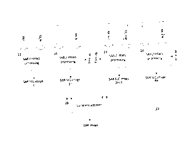
SAR processing is first implemented independently for every M subaperture.
Fig.
12 shows a block diagram of imaging means 20 with SAR processing according to
an embodiment example of the invention in which M=2, n=1. The N received
signals RX1-RX_N (first linear antenna 12) and N received signals RX_N+1-
RX_2*N (second linear antenna 14) recorded separately for each subaperture are
supplied in pairs to SAR/HRWS processing units 22 and 24, respectively (with
adjustable time lag). Each of units 22 and 24 generates an SLC (single-look
complex) SAR image from the supplied received signals from the subaperture
pairs.
The resulting 4 n SLC SAR images each represent a so-called look and can be
further processed in the known manner. To produce a single image with maximum
sensitivity, the 4n looks are coherently combined using a corresponding
addition
unit 26. Processing of the subaperture pairs respectively displaced in the
flight
direction should be displaced on the time axis for the purpose of co-
registration by
CA 02827279 2013-09-16
14
the respective time lag value for the subaperture group. This can be adjusted
by
inputting a correspondingly chosen time lag value into the units 24.
Moving target processing is first implemented independently for the two
antenna
planes. Fig. 13 shows a block diagram of moving target processing means 28
with
moving target indication according to one embodiment example of the invention.
The 2*N raw data, i.e., the 2*N received signals RX1-RX_N from the first
linear
antenna 12, separately recorded for each subaperture, and the separately
recorded received signals RX_N+1-RX_2*N from the second linear antenna 14
are each supplied to range pre-processing means 30 for generating "looks in
range". This pre-processing is optional. During pre-processing, the raw data
are
separated remotely by means of a frequency filter into individual data sets
("looks"), which later result in independent estimates of the moving target
velocity.
An averaging of these independent estimated values results in improved
precision. The decrease in the radar bandwidth that results from the formation
of
looks is useful in cases in which the SAR images need to have high resolution,
in
other words, the instrument has high bandwidth. However, in most cases moving
target indication requires only moderate resolution.
The range pre-processing means 30 also transform the received signals RX1-
RX_N from the first linear antenna 12, separately recorded for each
subaperture,
and the separately recorded received signals RX_N+1-RX_2*N from the second
linear antenna 14 to the azimuthal frequency range.
After transformation of the 2*N received signals to the azimuthal frequency
range,
the N received signals and/or channels of each linear antenna 12 and 14 are
subjected to M different digital optimal filters 32 in order to separate the M
branches of the folded moving target signal for the N received signals from
each
linear antenna 12 and 14. By separating the M branches of the folded moving
target signal by means of filtering using the digital optimal filter 32, a
signal
selection or suppression is carried out, which can be adjusted by moving
target
parameter 38.
CA 02827279 2013-09-16
The separated M branches are then focused using a correlation filter 34, which
is
adapted to the desired moving target signal. The correlation filter 34 can
also be
adjusted for this purpose by moving target parameter 38.
Finally, the image signal values generated by the correlation filter 34 and
5 originating from the two partial antennas 12 and 14 are conjugate
multiplied with
one another by means of All (along-track interferometry) processing means 36
in
the conventional All mode, in order to arrive at the desired phase information
and
therefore radial velocity measurement. Finally, the All processing means 36
supply, as output data, estimates of the moving target velocity for the
different
10 looks 40.
The means illustrated in the block diagrams of Fig. 12 and 13 can be
implemented
as hardware, for example, in the form of special circuits, more particularly,
ASICs
(application specific integrated circuits), FPGAs (field programmable gate
arrays),
or as software, for example, run on a powerful standard microprocessor and/or
15 digital signal processor (DSP) or combined with special hardware such as
ASICs
or FPGAs and software, run, for example, on a standard DSP. More particularly,
in
the case of processing on the ground and on a flying platform with an antenna
configuration as illustrated, for example, in Fig. 11, the means can be
implemented, for example, as a conventional computer, which is configured with
software for implementing the processing described herein and which can be
expanded with special hardware such as correspondingly powerful digital signal
processing circuits. The flying platform with the antenna configuration
according to
the invention can have means for recording the received signals from the
subapertures separately and for supplying them for further processing, for
example, by transmission to a ground station, which carries out the
processing.
Partial processing can also take place on the flying platform.
In what follows, a first, special embodiment example of the antenna
configuration
according to the invention will be described (embodiment example 1 in the
table
below).
CA 02827279 2013-09-16
16
The antenna configuration 10 operated in the Ka band (35.5 GHz) and
illustrated
in Fig. 14 has two linear antennas 12, 14, each having 4 subapertures RX1-RX4
and/or RX5-RX8 having the length L =2m, arranged in a row in the flight
direction
18. The azimuthal resolution of the SAR image is 1 m. To improve (double) the
narrow strip width that is possible at this high resolution only using
conventional
means, two subapertures each are operated in the HRWS mode (M=2, n=1).
The second level of 4 subapertures is offset by B2 = 0.5 m in the flight
direction.
Approximately the performance values listed in table 1 are achieved. The
advantage of configuration 10 consists in a wide strip width in combination
with a
very large moving target velocity measurement range.
CA 02827279 2013-09-16
17
Table 1 (all moving target velocities indicated in slant distance)
Parameter Embodiment Example 1 Embodiment Example 2
SAR azimuthal resolution 1 m 0.5 m
PRF 3.8 kHz 1.9 kHz
Maximum strip width with 45 km 90 km
a 45 angle of incidence
Clear velocity range 64 mis 32 m/s
Typical minimum velocity 2 m/s 1 m/s
(max. ¨5dB signal loss)
PRF blind velocities nx15.8mIs nx8m1s
Width of a PRF blind 25% 25%
band as a % of blind
velocity
In what follows, a second special embodiment example of the antenna
configuration according to the invention will be described (embodiment example
2
in the table above).
In this example, a narrower clear velocity measurement range for the moving
target will suffice. The offset between the two linear antenna configurations
can
therefore measure 1m. At the same time, the subaperture length should be L =
lm
in order to produce a high azimuthal resolution for the SAR instrument. The
upper
antenna configuration can now be integrated into the lower, so that a single
linear
antenna results, in this configuration with 17 subapertures, as illustrated in
Fig. 15.
In each case four subapertures are operated in HRWS mode, in order to obtain
wide strip widths despite low azimuthal resolution. The advantages of this
architecture are: a low minimum velocity corresponding to the overall antenna
length and a wide strip width with a simultaneously large moving target
velocity
measurement range.
CA 02827279 2013-09-16
18
Finally, significant advantages of the invention will be summarized in the
following.
The high pulse repetition frequency (PRF) that is required in conventional
GMTI
SAR instruments for detecting fast moving targets has thus far required that
the
instrument be designed for imaging narrow strips of ground. This is a
disadvantage. Moreover, it prevents the design of a single instrument that has
a
simultaneous recording mode for both GMTI SAR and for conventional imaging
SAR, which is generally designed for wide strips.
In contrast, the present invention offers the following advantages:
1. The invention specifies how the PRF of a conventional GMTI SAR
instrument can be decreased by introducing additional subapertures on the
receiving side. Each of these subapertures has separate signal recording.
The strip width to be imaged and/or the maximum velocity of a detectable
moving target can thereby be increased.
2. The invention specifies how a single instrument can be designed for both
GMTI SAR and conventional SAR functionality and can be operated in a
single imaging mode. Differentiation is made first during processing. The
additional subapertures that are required for the GMTI SAR mode at low
PRF can be used in the SAR mode in order to increase the sensitivity of the
instrument.
3. The invention specifies which processing sequences may be used in order
to arrive at both SAR image data and moving target indication data using
one and the same set of raw data.
4. The maximum velocity of a detectable moving target can be adjusted
independently of the length of the subapertures.
CA 02827279 2013-09-16
19
5. The blind velocities that occur at low pulse repetition frequencies are
displaced in the invention by varying the PRF in alternating azimuthal looks.
As a result, moving targets that in one look are covered by a blind velocity
are visible in the other look.
CA 02827279 2013-09-16
REFERENCE SIGNS AND ACRONYMS
10 Antenna configuration
11 Antenna configuration
5 12 First row of subapertures for receiving reflected signals
14 Second row of subapertures for receiving reflected signals
16 Single row of subapertures for receiving reflected signals
18 Flight direction
20 SAR processing means
10 22 SAR/HRWS processing unit
24 SAR/HRWS processing unit with time lag
26 Coherent addition unit
28 Moving target processing means
Range pre-processing means
15 32 Digital optimal filter
34 Correlation filter
36 ATI processing means
38 Moving target parameter
Velocity estimate of a moving target for a specific look
20 RX1 - RX_N N subapertures of the first row 12
RX_N+1 ¨ RX_2*N N subapertures of the second row 14
TX Transmitting aperture
Aperture length in flight direction 18
B2 Offset between the two rows 12 and 14 in flight
25 direction 18
ATI Along-Track lnterferometry
GMTI Ground Moving Target Indicator
HRWS High Resolution Wide Swath
MDV Minimum Detectable Velocity
30 PRF Pulse Repetition Frequency
SAR Synthetic Aperture Radar
CA 02827279 2013-09-16
21
SLC single look complex