Note : Les descriptions sont présentées dans la langue officielle dans laquelle elles ont été soumises.
CA 02828932 2013-09-03
CRANK DRIVE
DESCRIPTION
The invention relates to a crank drive having a crankshaft journal with a
concave-
shaped surface, a bearing element, in which the crankshaft journal is
rotatably mounted,
and a bearing shell, which is arranged between the crankshaft journal and the
bearing
element and which has a convex-shaped first surface, which is associated with
the
concave-shaped surface of the crankshaft journal.
The crankshaft journal can be a crank journal of a crankshaft, on which the
large
connecting rod eye of a connecting rod is mounted. In this case the connecting
rod or its
large connecting rod eye forms the bearing element within the meaning of the
present
invention. The crankshaft journal can however also be a main bearing journal
of the
crankshaft, by means of which the crankshaft is mounted rotatably in a bearing
receptacle of the engine housing. In this case the bearing receptacle of the
engine
housing forms the bearing element within the meaning of the present invention.
In many crank drives known from the prior art, the crankshaft journal is
cylindrical, and
a hollow cylindrical bearing shell is arranged between the crankshaft journal
and the
bearing element, which bearing shell has a constant wall thickness as viewed
over its
width. This hollow cylindrical bearing shell thus has a constant circular
cross section
over its axial extent.
A crank drive consisting of a non-cylindrical, concave-shaped crank journal of
a
crankshaft and a connecting rod mounted rotatably thereon with its large
connecting rod
eye is known from international patent application WO 2008/129395 A2. With
this
known crank drive, the crank journal has a concave-shaped surface, and the
surface of
the large connecting rod eye which faces the crank journal is correspondingly
convex-
shaped, so the two mutually facing surfaces are matched to each other.
According to a
preferred embodiment of the invention disclosed in WO 2008/129395 A2, the
large
connecting rod eye is mounted on the crank journal, i.e. without interposition
of a
bearing shell. Furthermore, an embodiment is mentioned in the general
description part
of WO 2008/129395 A2, with which a bearing shell is arranged between the crank
journal and the large connecting rod eye. In this embodiment with the bearing
shell, the
surface of the large connecting rod eye facing the crank journal is also
matched to the
concave shape of the crank journal surface.
CA 02828932 2013-09-03
2
Thus, the WO 2008/129395 A2 gives a person skilled in the art the technical
teaching
that the convex curvature of the surface of the large connecting rod eye must
run in
exactly the same way as the concave curvature of the crank journal. It is
therefore
necessary to give the inner bearing face of the large connecting rod eye,
which interacts
with the crank journal, a convex shape corresponding to the concave shape of
the crank
journal by means of machine-cutting. In the process, considerable measurement
demands must be met to achieve the exact precision of shape necessary for the
sliding
bearing of the connecting rod on the crank journal. The creation of such a
convex shape
on the large connecting rod eye with the precision necessary for the bearing
of the
connecting rod on the crank journal while complying with the necessary
tolerances is
therefore complex in manufacturing terms. The production costs for such
connecting
rods are therefore comparatively high, so the production costs for crank
drives equipped
with such connecting rods are also high.
A further disadvantage of the solution known from WO 2008/129395 A2 can be
seen in
that, because the bearing face of the large connecting rod eye matches the
concave
shape of the surface of the crank journal for a crankshaft with a given
concave crank
journal surface, only one single concrete connecting rod ever fits. Therefore,
only one
single crank drive design is possible. In the case of this known solution, it
is not
possible to combine different connecting rods with a certain specified
crankshaft and in
this manner allow the designer greater flexibility when designing the crank
drive.
The invention is based on the object of providing a crank drive having the
features of
the preamble of Patent Claim 1, which is simple to manufacture and
comparatively
inexpensive to produce. It should also be possible to provide crank drives of
different
designs in a simple manner on the basis of a certain, specified crankshaft
design.
This object is achieved by a crank drive having the features of Patent Claim
1.
Advantageous developments are specified in the subclaims.
The invention emanates from a crank drive having a crankshaft journal with a
concave-
shaped surface, a bearing element, in which the crankshaft journal is
rotatably mounted,
and a bearing shell, which is arranged between the crankshaft journal and the
bearing
element and which has a convex-shaped first surface, which is associated with
the
concave-shaped surface of the crankshaft journal. To achieve the possibility
of
combining different bearing elements for differently designed crank drives
with one and
= CA 02828932 2013-09-03
3
the same crank shaft, it is proposed according to the invention for the
bearing shell to
have a second surface, which is associated with the bearing element and which
is
designed in such a manner that the bearing shell has a non-constant cross
section as seen
in the longitudinal direction of the crankshaft journal, and that the surface
of the bearing
element which faces the bearing shell is matched in shape to the second
surface of the
bearing shell, and wherein in particular the second surface of the bearing
shell is
cylindrical or concave and has a smaller curvature than the concave-shaped
surface of
the crankshaft journal. In this manner it is no longer necessary to match the
shape of the
surface of the bearing element which faces the crankshaft journal to the
concave-shaped
surface of the crankshaft journal. The simple replacement of a first bearing
shell having
a particular surface facing the bearing element with a second bearing shell
having a
differently designed surface facing the bearing element means that differently
designed
bearing elements can be used simply and inexpensively for one and the same
crankshaft,
to produce different crank drives.
The fact that the second surface of the bearing shell which is associated with
the bearing
element is formed in such a manner that the bearing shell cross section has a
non-
constant cross section as seen in the longitudinal direction of the crankshaft
journal, i.e.
over the bearing shell width, means that the surface of the bearing shell
which faces
away from the crankshaft journal and is associated with the bearing element
can have a
shape which is either not curved (and therefore has a cylindrical shape), or
the curvature
of which is much smaller than the curvature of the surface of the bearing
shell which is
associated with the crankshaft journal. This achieves the possibility of
forming the
bearing face of the bearing element which faces the bearing shell either
cylindrically or
else at least with a less distinctive convex shape having a curvature which is
much
smaller than it would have to be if the said bearing face of the bearing
element had to be
matched in shape to the concave surface of the crankshaft journal.
Therefore, the invention provides the designer the freedom to design the shape
of the
surface of the bearing element which faces the crankshaft journal completely
independent from the shape of the surface of the crankshaft journal. The
bearing
element can therefore be produced with much less effort in manufacturing
terms.
Complex measurements with expensive measuring instruments for complying with
the
necessary shape of the bearing face of the bearing element are omitted
completely or
can be carried out with much less effort and simpler measuring instruments.
The
production costs for the bearing element of the crank drive according to the
invention
CA 02828932 2013-09-03
4
can thereby be greatly reduced compared to the solution known from WO
2008/129395
A2.
According to a first possible embodiment of the invention, the second surface
of the
bearing shell is formed cylindrical. Both the bearing shell and the bearing
element can
in this case be produced inexpensively and particularly simple in
manufacturing terms.
In this embodiment of the invention, the recess of the bearing element which
accommodates the bearing shell can be designed as a simple cylindrical recess,
for
example a simple cylindrical bore. If the bearing element is e.g. a connecting
rod having
a large connecting rod eye, then a simple cylindrical bore suffices to
accommodate the
bearing shell and to rotatably mount the crankshaft journal with the concave
surface.
Strict shape and tolerance limits do not have to be observed during
manufacturing, as
would be necessary if the surface of the large connecting rod eye which faces
the
crankshaft journal had to be matched to the concave shape of the crankshaft
journal. A
simple, coarse machine-cutting of the inner surface of the cylindrical bore of
the bearing
element is sufficient. The matching of the first, convex-shaped surface of the
bearing
shell which faces the crankshaft journal to the concave-shaped surface of the
crankshaft
journal is much simpler and more cost-effective in manufacturing terms than
the
matching of the surface of the bearing element which faces the crankshaft
journal. The
complex "bearing element" component can thus be designed to be simple and easy
to
produce without the advantages of a concave/convex-shaped pair of bearing
faces on the
crankshaft journal. The bearing shell is much smaller than the bearing
element, so it is
simpler to process or machine. Moreover, the bearing shell is axially
symmetrical and
has a much more uniform distribution of mass than e.g. a bearing element
formed as a
connecting rod. The convex first surface of the bearing shell does not have to
be
produced by machine-cutting, as would be the case with a more complex bearing
element, but can also be produced using other different production methods
such as
pressing, casting, sintering or forging.
According to a second possible embodiment of the invention, the second surface
of the
bearing shell is formed concave, the curvature of this second surface of the
bearing shell
being smaller than the curvature of the concave surface of the crankshaft
journal. This
achieves the situation in which the surface of the bearing element which faces
the
crankshaft journal at least does not have to be as greatly curved as would be
necessary if
the surface of the bearing element which faces the crankshaft journal had to
be matched
to the concavely curved surface of the crankshaft journal. Also in this
embodiment of
CA 02828932 2013-09-03
=
the invention, the advantage that the bearing element can be produced
inexpensively
and with comparatively little manufacturing effort, is retained.
Common to both the above-described embodiments of the invention is that the
manufacturing effort for the actual bearing element, that is, the connecting
rod having
the large connecting rod eye or the bearing element of the engine housing
which
accommodates the main bearing journal of a crankshaft, can be produced with
much
less effort in manufacturing and measurement terms, as a result of which
production
costs can be greatly reduced. It is much less complex in manufacturing terms
and
therefore also much more cost-effective to match only the bearing shell with
its first
surface which faces the crankshaft journal to the concave shape of the
crankshaft
journal than to match the bearing face, which faces the crankshaft journal, of
the bearing
element itself to the concave shape of the crankshaft journal. The step of
matching the
shape of the bearing face of the bearing element to the concave-shaped surface
of the
crankshaft bearing, which increases production costs and manufacturing effort,
is thus
according to the invention shifted away from the bearing element into the
bearing shell.
The advantages of mounting the bearing element on a crankshaft journal having
a
concave-shaped bearing surface and the simple design of the bearing element
with a
cylindrical or only slightly curved convex bearing face can be combined with
each other
by the invention and utilised at the same time.
The invention is explained in more detail below using a schematic drawing. It
is shown;
Fig. la an embodiment of the invention having a bearing element
configured as a
connecting rod, wherein the connecting rod is mounted with its large
connecting rod eye on a crank journal of a crankshaft, in a section showing
only one part of the crank drive;
Fig. lb an embodiment of the invention in which the crankshaft journal
is
configured as a main bearing journal of a crankshaft, having a bearing shell
comparable to Fig. la, in a section showing only one part of the crank drive;
Fig. 2a an embodiment of the invention having a bearing element which
is
configured as a connecting rod and is mounted with its large connecting rod
eye on a crank journal of a crankshaft, in an embodiment of the invention
which is modified with respect to Fig. la and likewise in a section showing
only one part of the crank drive;
CA 02828932 2013-09-03
6
Fig. 2b an embodiment of the invention which is modified with respect to
Fig. lb,
having a bearing shell according to the invention which is arranged on a
main bearing journal of a crankshaft, in a section showing only one part of
the crank drive;
Fig. 3 a crank drive according to the prior art.
Fig. 3 shows a crank drive K known from the prior art according to WO
2008/129395
A2, using the example of a bearing element 3 mounted on a crankshaft journal
2. The
bearing element 3 is configured as a connecting rod. The bearing face 1 of the
crankshaft journal 2 which faces the bearing element 3 has a concave shape.
The surface
of the bearing element 3 which faces the said bearing face 1 has a convex
shape, which
is matched to the concave shape of the bearing face 1 of the crankshaft
journal 2. In the
embodiment shown in Fig. 3, which is the preferred embodiment according to WO
2008/129395 A2, there is no bearing shell arranged between the bearing element
3 and
the crankshaft journal 2. However, in the description of WO 2008/129395 A2 it
is
mentioned that a bearing shell can be arranged between the bearing element 3
and the
crankshaft journal 2. The present invention proceeds from this exemplary
embodiment
mentioned only briefly in the description of WO 2008/129395 A2. The main
bearing
journals of the crank drive K are referred to with 2'.
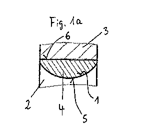
Figures la and lb show a first embodiment of the present invention in a
schematic
diagram which shows only one section of the crank drive according to the
invention.
According to this first embodiment of the invention, the bearing shell 4,
which is
arranged between the crankshaft journal 2 and the bearing element 3, is formed
with a
non-constant cross section over the longitudinal extent of the crankshaft
journal 2 (that
is, as seen parallel to the drawing plane). In the subject matter shown in
Fig. I a, the
crankshaft journal 2 is formed as an eccentrically arranged crank journal of a
crankshaft
(not shown in detail). The bearing element 3 is configured as a connecting
rod, which is
mounted with its large connecting rod eye on the crank journal 2. Similarly,
in Fig. lb,
the crankshaft journal 2, which is configured as a main bearing journal on a
crankshaft
(not shown in detail), is mounted in a bearing element 3 by means of a bearing
shell 4.
In the exemplary embodiment shown in Fig. lb, the bearing element 3 is a
bearing
receptacle which is connected fixedly to an engine housing of an internal
combustion
engine (not shown) for the rotatable accommodation of the main bearing journal
of the
crankshaft.
CA 02828932 2013-09-03
7
Both in Fig. la and in Fig. lb, the bearing element 4 has a non-constant cross-
sectional
profile as seen in the longitudinal direction of the crankshaft journal 2,
that is, parallel to
the drawing plane. The bearing shell 4 has a convex-shaped first surface 5,
which is
associated with the concave-shaped surface 1 of the crankshaft journal 2. The
first
surface 5 of the bearing shell 4 is matched in shape to the concave-shaped
surface 1 of
the crankshaft journal 2. The bearing element 3 has a cylindrical recess,
which is
configured as a bore, in which the cylindrical second surface 6 of the bearing
shell 4 is
accommodated. In this manner the possibility is achieved of producing the
bearing
element 3 with little effort in manufacturing and measurement terms without
having to
observe particular shape specifications and tolerances during production of
the bearing
element 3.
In the embodiments of the invention shown in Fig. la and lb, it is merely
necessary to
provide a cylindrical recess, for example in the form of a cylindrical bore,
in the bearing
element 3 in order to accommodate the cylindrical, outer, second surface 6 of
the
bearing shell 4. The step of producing a convex surface 5 matched to the
concave-
shaped surface 1 of the crankshaft journal 2, which is more complex in
manufacturing
terms, is shifted away from the bearing element 3 and towards the bearing
shell 4 in the
invention. The production of the convex-shaped first surface 5 can be realised
much
more simply, with less effort and lower costs with the production of the
comparatively
small bearing element 4. The substantially larger and more complex component,
namely
the bearing element 3, only has to be provided with a simple cylindrical
recess.
In this manner the present invention makes it possible for only a cylindrical
recess to
have to be provided on a complex component of the crank drive, namely the
bearing
element 3, so the said complex component can be produced simply and
inexpensively.
At the same time, the advantages associated with the mounting of the bearing
element
on a concave-shaped surface of the crankshaft journal are retained. These
advantages
are described in detail in the document WO 2008/129395 A2.
A second embodiment of the invention is shown in Fig. 2a and 2b. In Fig. 2a,
the
bearing element 3 is configured as a connecting rod. This connecting rod is
mounted
with its large connecting rod eye on a crankshaft journal 2 of a crankshaft
(not shown in
detail) with interposition of a bearing shell 4. In the subject matter of Fig.
2b, however,
the crankshaft journal 2 is configured as a main bearing journal of a
crankshaft (not
shown in detail), the crankshaft journal 2 being accommodated rotatably in a
bearing
CA 02828932 2013-09-03
8
receptacle with interposition of a bearing shell 4. The said bearing
receptacle is
connected fixedly to an engine housing (not shown) and forms the bearing
element 3.
Both in the embodiment of Fig. 2a and the embodiment of Fig. 2b, the
crankshaft
journal 2 has a concave-shaped surface I. The bearing shell 4 arranged between
the
bearing element 3 and the crankshaft journal 2 has a first convex-shaped
surface 5,
which faces the crankshaft journal. The convex-shaped surface 5 is matched in
shape to
the concave-shaped surface 1 of the crankshaft journal 2.
The bearing shell 4 has a second concave-shaped surface 6 on the side facing
away from
the crankshaft journal 2. This second, concave-shaped surface 6 has a
substantially less
pronounced curvature than the curvature of the concave-shaped surface 1 of the
crankshaft journal 2. Accordingly, the surface of the bearing element 3 which
faces the
second surface 6 of the bearing shell 4 also has a much smaller curvature than
would be
necessary if it had to be matched to the concave-shaped surface 1 of the
crankshaft
journal 2. The curvature of the second, concave-shaped surface 6 of the
bearing shell 4
therefore defines the curvature of the convex-shaped bearing face of the
bearing element
3 which faces the bearing shell 4. For this reason, the shape of this convex-
shaped
bearing face of the bearing element can be designed completely independently
from the
concave-shaped bearing face of the crankshaft journal 2.
The fact that in the embodiment of the invention according to Fig. 2a and 2b -
as in the
first embodiment according to Fig. la and lb - the cross section of the
bearing shell 4
does not have a constant profile in the direction of the longitudinal extent
of the
crankshaft journal 2, that is, as seen parallel to the drawing plane, means
that the surface
of the bearing element 3 which faces the bearing shell 4 can be much less
curved than
would be necessary if the bearing shell 4 had a constant cross section in the
direction of
the longitudinal extent of the crankshaft journal 2. Then the curvature of the
surface of
the bearing element 3 which faces the crankshaft journal 2 would have to be
matched in
curvature to the concave-shaped surface 1 of the crankshaft journal 2.
In the embodiment according to Fig. 2a and 2b, benefits can be gained from the
advantages of the larger contact face between the bearing element 3 and the
bearing
shell 4, while at the same time less manufacturing effort is retained for the
production of
the bearing element 3, because the much smaller curvature of the surface of
the bearing
element 3 which faces the bearing shell 4 requires much less effort in
measurement and
CA 02828932 2013-09-03
9
manufacturing terms than the production of a highly curved convex surface
complying
with the shape and measurement tolerances necessary for the application.
Common to both the above-described embodiments of the invention is that a very
flexible crank drive is provided. For example different connecting rods can be
combined
with one and the same crankshaft, it only being necessary for differently
designed
bearing shells 4 to be arranged between the crankshaft journal and the large
connecting
rod eye of the connecting rod. Similarly, differently shaped bearing brackets
can be
used to accommodate the main bearing journals of one and the same crankshaft,
it only
being necessary for correspondingly arranged bearing shells 4 to be arranged
between
the crankshaft main bearing journal and the bearing bracket. In this manner,
bearing
elements which are optimally matched to the actual application can easily be
combined
with one and the same crankshaft. It is also possible to use one and the same
crankshaft
in different engine housings with differently designed bearing brackets for
accommodating the crankshaft.
The above-mentioned advantages are of great importance in practice. The
bearing
geometry, that is, the geometries of the bearing faces in functional
connection with each
other, can be optimised with the invention with respect to the application,
for example
with respect to dynamic behaviour of the bearing partners, lubrication of the
bearing,
process parameters during engine operation etc. This can be utilised e.g. with
respect to
the very different pressure levels at which engines are operated. For
instance, very
different pressures arise during operation in petrol engines and diesel
engines. The
pressures arising during operation are much greater in diesel engines than in
petrol
engines. Therefore, for example, the demands on the bearing of the connecting
rods on
the crank journal of the crankshaft or on the bearing of the crankshaft main
journal in
the engine housing are also different in diesel engines and petrol engines, so
the
respective bearings must be designed differently to achieve the necessary
service life of
the crank drive in each case. The present invention now makes it possible to
use one and
the same crankshaft in different engines, despite these different demands,
since the
necessary differences with respect to the design of the bearings are realised
according to
the invention by the use of a bearing shell which is adapted to the
application together
with a connecting rod which is matched to the bearing shell.
The bearing shell solution according to the invention provides the designer
with greater
flexibility with respect to application-related adaptation and optimisation
processes. The
pair of bearing faces between the bearing element 3 and the bearing shell 4
can be
CA 02828932 2013-09-03
designed differently in a simple manner, without the layout and design of the
crankshaft
itself having to be changed.