Note : Les descriptions sont présentées dans la langue officielle dans laquelle elles ont été soumises.
CA 02829626 2013-09-09
WO 2012/122517 PCT/US2012/028593
DEVICE AND METHOD FOR THE GEOMETRIC DETERMINATION OF
ELECTRICAL DIPOLE DENSITIES ON THE CARDIAC WALL
FIELD OF THE INVENTION
[0001] The present invention relates generally to the localization and
treatment of
cardiac arrhythmias, and more particularly to devices and methods for real
time, non-contact
imaging and distance measurements using ultrasound for dipole density mapping,
as well as
methods for diagnosing tissue health.
BACKGROUND OF THE INVENTION
[0002] Systems used to localize the origin of cardiac arrhythmias measure
potentials
(e.g. in millivolts) in the cardiac chambers and localize them on a three
dimensional
representation of the cardiac chamber wall. The measurement of the electrical
activity present
on the cardiac walls is called mapping. For this purpose, a multiple electrode
mapping
catheter may be positioned within the heart such that multiple potentials can
be
simultaneously measured at different locations on the wall of the cardiac
chamber without
having direct wall contact (non-contact mapping). The cardiac chamber is
visualized as a
three dimensional structure, either directly by moving one or more mapping
electrodes within
the corresponding heart chamber or by importing an anatomical geometry of the
cardiac
chamber from an imaging device (e.g. Computed Tomography, MRI, or ultrasound).
The
electrical activity within the heart can be measured with the multi-electrode
mapping
catheter, which may be able to simultaneously measure potentials at different
points in three
dimensional space. In the current systems, the measured potentials from the
non-contact
multi-electrode mapping catheter do not directly correspond to the electrical
activity on the
cardiac wall as measured with an electrode with direct wall contact (contact
mapping). The
measured potentials of the non-contact mapping system have to be converted
with computer
programs and extrapolated into virtual electrograms projected on the heart
chamber of the
mapping system.
[0003] U.S. Patent 5,297,549 (Beatty, et al.) discloses a method of
generating a three-
dimensional map of electrical activity in a heart chamber as well as a two-
dimensional map
of the electrical activity within the endocardial surface. Beatty generates
the infomiation via
CA 02829626 2013-09-09
WO 2012/122517
PCT/US2012/028593
an array of electrodes placed in a heart chamber utilizing impedance
plethysmography, while
one electrode serves as a reference.
[0004] The current conversion methods suffer various instabilities, and
further
processing, termed regularization, must be applied to maintain stability.
Regularization
decreases spatial resolution. Another limitation of the current methods is
that the provided
potentials represent only the mean electrical activity summed across a large
region of tissue,
with cells consisting of membranes separating electrical dipoles.
[0005] Since the localization of cardiac arrhythmias by the use of
potentials is
imprecise, the successful treatment of cardiac arrhythmias has been difficult
and has
demonstrated limited success and reliability. There is, therefore, a need for
improved
methods of localizing cardiac arrhythmias.
SUMMARY
[0006] The present invention discloses devices and methods for real time,
non-contact
imaging and distance measurements using ultrasound for dipole density mapping,
as well as
methods for diagnosing tissue health. In one aspect, the present invention
includes a device
comprising one or more catheters, each catheter comprising a shaft. The shaft
may include a
lumen and may be steerable. The shaft may include, typically near its distal
end, one or more
components selected from group consisting of: electrodes, such as electrodes
configured to
record electrical activity of tissue; transducers such as ultrasound
transducers; sensors, such
as ultrasound sensors; ultrasound crystals configured to both transmit and
sense ultrasound
waves; and combinations of these. The device is constructed and arranged to
produce
continuous, real-time images of a patient's tissue, as well as information
related to electrical
activity present in the tissue. For example, a user, such as a clinician may
image a patient's
cardiac chamber, including the cardiac walls. The device is also capable of
providing tissue
information, for example, tissue movement and tissue thickness. Additionally,
the device is
configured to produce distance measurements by analyzing at least one of the
sensors
recorded angles or frequency changes. Non-limiting examples of distance
measurements
include: distance between the multiple electrodes and the wall of the cardiac
chamber and
distance between the multiple electrodes and the transducer and/or sensor. The
device may
be configured to provide a tissue diagnostic through an analysis of both
tissue motion
2
CA 02829626 2013-09-09
WO 2012/122517
PCT/US2012/028593
info' ____________________________________________________________________
illation and cell electrical signals. The cell electrical signals may be
recorded by the
multiple electrodes, while tissue motion information may be gathered by the
multiple
electrodes and/or the sensor. The device is configured to provide exact foci
and conduction-
gap position information, such that ablation is performed with an increased
level of precision.
Small conduction paths, including "gaps" in a line, are equally relevant as
foci. The device
may include an ablation catheter, such as an ablation catheter that can be
precisely delivered
through an open lumen of a second device catheter, or through a sheath.
[0007] In
some embodiments, the device may include a catheter which is further
configured as a delivery sheath. For example, a first catheter may comprise a
lumen, such
that a separate ablation catheter may be slidingly received by the first
catheter. Additionally,
a single sheath may be provided to allow the first catheter and the ablation
catheter to pass
there though. This construction would eliminate the need for multiple sheath
devices.
[0008] In
some embodiments, one or more catheters of the device may be steerable.
For example, a user may determine the ablation site via real-time tissue
analysis and imaging,
and subsequently a catheter may be steered to the desired location. Steering
of one or more
catheters may be achieved via cables, such as cables which may be housed in a
lumen of a
delivery sheath.
[0009] The
device comprises a transducer, preferably an ultrasound transducer
configured to produce sound waves, typically at a frequency between 5 and 18
MHz. The
sound waves may be at a constant rate or provided in a pulsed manner. The
device may
comprise multiple transducers. One or more transducers may be positioned on
one or more
catheters of the device, such as on or near a distal portion of a catheter.
One or more
transducers may be further configured as sensors, such as ultrasound crystals
that both record
and emit sound waves.
[0010] The
device comprises a sensor, preferably an ultrasound sensor configured to
receive the sound waves produced by the ultrasound transducer. The device may
comprise
multiple sensors. One or more sensors may be positioned on one or more
catheters of the
device, such as on or near a distal portion of a catheter. One or more sensors
may be further
configured as transducers, such as ultrasound crystals that both record and
emit sound waves.
[0011] The
sensors, transducers, or combination sensor/transducers may be positioned
on the device in various locations including but not limited to: attached to
the shaft of the
3
CA 02829626 2013-09-09
WO 2012/122517
PCT/US2012/028593
catheter; housed within the shaft of the catheter, for example, the sensor
and/or transducer
may be slidingly received by the shaft; at the geometric center of each of the
multiple
electrodes; proximate to at least one of the multiple electrodes; mounted to a
multiple arm
assembly; and combinations of these. The device may include one or more
electrodes
configured to record electrical activity in the tissue of cells. Various
ratios of electrodes to
sensors, transducers, or combination sensor/transducers may be included. In
one
embodiment, a ratio of two electrodes to one ultrasound crystal is provided,
such as a single
component with one ultrasound crystal and an electrode positioned at each end
of the crystal.
In another embodiment, a ratio of five electrodes to two sensor/transducers is
provided, such
as a catheter shaft including two assemblies and a single electrode. Each
assembly includes
an ultrasound crystal with an electrode positioned at each end.
[0012] The
transducer and/or the sensor may be rotated, which may include a partial
rotation or a full 3600 rotation. Alternatively or additionally, the sensor
and/or transducer
may be translated along a linear axis. In one embodiment, the sensor and/or
transducer
comprise a piezoelectric film. For example, a wire may be electrically
connected to a first
electrode where a portion of the wire comprises a piezoelectric film.
Alternatively, the sensor
and/or transducer may comprise a piezoelectric cable.
[0013] In
some embodiments, the sensor and transducer may comprise a single
component, for example, a single crystal. Alternatively, the sensor and/or
transducer may
comprise an array of components, for example, a circumferential array of
ultrasound crystals.
Each of the ultrasound crystals may be attached to one or more electrodes
configured to
record electrical activity of living cells.
[0014] The
device further comprises a first receiver that receives mapping
information from multiple electrodes included in one or more catheters
configured to perform
mapping of cellular electrical activity, such as electrocardiogram activity.
The electrodes are
placed in a cardiac chamber of the patient's heart. The device further
includes a second
receiver that receives anatomical information. The anatomical information may
be a generic
heart model, or more preferably tissue contour and other anatomical
infounation recorded
from the patient's own heart. A dipole density module detennines the database
of dipole
densities, in the table form d(y), where y represents the three-dimensional
location on the
heart tissue including that particular dipole density. The potential at
various other locations
4
CA 02829626 2013-09-09
WO 2012/122517
PCT/US2012/028593
x, within a cardiac chamber and termed V(x), are recorded by the multiple
electrodes. Solid
angle th(x,y) represents the solid angle for a triangle projection between
location x (electrode
location in chamber) and y (triangle location on chamber wall). The dipole
density module
deterniines the dipole density for individual triangle shaped projections onto
the cardiac
chamber wall based on the following: each triangle projection at location y
contributes 6(x,y)
times the dipole density d(y) to the potential V(x) at the point x.
[0015] In a preferred embodiment, the device comprises a software
program, e.g.,
such as a software program loaded onto a personal computer; an ECG system; a
cardiac
tissue ablation system and/or an imaging system. The number of triangles
determined by the
dipole density module is sufficiently large (triangle area small enough) such
that the dipole
density for each triangle projection is relatively constant. Typically 1000 or
more triangles
are used in the calculations, such as a calculation based on a standard sized
Left or Right
Atrium. Larger numbers of triangles are used for larger sized chambers.
[0016] In another preferred embodiment, the patient is being diagnosed
and/or treated
for a heart condition, such as an arrhythmia. The electrodes are included at
the distal end of
one or more mapping catheters and are placed into a chamber of the patient's
heart to record
potentials. An imaging instrument, such as an instrument that provides a
generic model of a
heart, or an instrument which provides an anatomical model of the patient's
heart, delivers the
anatomical information to the second receiver. In one embodiment, the imaging
instrument is
one or more of: Computed Tomography; MRI; ultrasound; and an ECG system with
mapping
catheter. Alternatively or additionally, an imaging instrument may be
integrated into the
device, such as an ultrasound unit configured to produce image and distance
inforniation
from signals received from one or more ultrasound sensors.
[0017] In another preferred embodiment, the dipole density module
implements an
algorithm configured to assist in the creation of the database of dipole
densities. The
algorithm may be a progressive algorithm configured to be modified or refined
to improve
spatial and/or time resolution of the database. The dipole density module may
determine a
map of dipole densities at corresponding time intervals. A synthesis of maps
represents a
cascade of activation sequences of each corresponding heart beat.
[0018] In another preferred embodiment, the device includes a third
receiver. The
third receiver collects mapping information from one or more skin electrodes.
The dipole
CA 02829626 2013-09-09
WO 2012/122517 PCT/US2012/028593
density module uses the skin electrode signals to calculate or recalculate the
database of
dipole densities, using equations listed herebelow.
[0019] According to another aspect of the invention, a system for
creating a database
of dipole densities at the surface of one or more cardiac chambers of a
patient's heart is
provided. In addition to the device of the present invention, the system
includes one or more
multiple electrode catheters; an ablation device; at least one surface or skin
electrode; a
transducer; and a sensor. A separate imaging instrument may be included in the
system. In a
preferred embodiment, the mapping catheter is also used for ablating tissue
identified by the
database of dipole densities and positioned in the heart chamber using the
real-time imaging.
The system includes a monitor to display the real-time image and dipole
density information,
such as information displayed in relative geometry to the chamber of the
patient's heart.
[0020] According to another aspect of the invention, a method of creating
a database
of dipole densities at the surface of one or more cardiac chambers of a
patient's heart is
provided. The method can be used to diagnose and/or treat complex cardiac
arrhythmia
disease. In a typical configuration, complex electrograms are identified, such
as a method in
which three or more complex electrograms are identified. In a preferred
embodiment, the
method is used to diagnose and/or treat Atrial Fibrillation (AF), Ventricular
Tachycardia
(VT), Atrial Flutter and tissue scarring, such as tissue scarring caused by an
intra-cardiac
defibrillator (ICD). In another preferred embodiment, the method is used to
detect
ventricular ischemia and/or quantify myocardial function. The method includes
placing an
array of multiple electrodes within a chamber of the patient's heart to
measure potentials and
calculating the distance or movement information by analyzing signals received
from a sound
sensor. The array of multiple electrodes may or may not be repositioned to
determine dipole
densities.
[0021] In another preferred embodiment, the method further includes
placing one or
more skin electrodes. The information recorded by the skin electrodes is used
to determine
the database of dipole densities. In yet another embodiment, the method
further comprises
calculating tissue thickness information.
[0022] According to another aspect of the invention, a medical method for
obtaining
electrical and anatomical information related to a patient's cardiac
chamber(s) is disclosed.
In a first step, a user may insert a device into a delivery system. The device
may be any
6
CA 02829626 2013-09-09
WO 2012/122517
PCT/US2012/028593
device described hereabove. In a next step, the user may advance the device
through the
delivery system and into a heart chamber. In a next step the device and/or
delivery system
may be steered such that the distal end of the device is positioned
approximately in the
geometric center of the heart chamber. Once the device is positioned within
the heart
chamber, measurements may be obtained and analyzed consistent with
measurements and
methods disclosed herein.
[0023] According to another aspect of the invention, a method for
diagnosing tissue is
disclosed. The preferred method comprises placing a distal end of an electrode
catheter into
one or more cardiac chambers of a patient, where the electrode catheter
comprises at least one
electrode and at least one ultrasound element. In a next step, anatomical
information, such as
tissue movement, may be determined via the at least one ultrasound element. In
a next step,
the electrical charge of a tissue may be determined via the at least one
electrode. Lastly, by
analyzing tissue movement and electrical charge information, tissue health may
be
determined.
[0024] For example, electrical information indicative of adequate
electrical activity
and anatomical infonnation indicative of adequate tissue motion correlates to
presence of
healthy tissue. Additionally, electrical information indicative of adequate
electrical activity
and anatomical information indicative of inadequate tissue motion correlates
to presence of at
least one of ischemic tissue or hibernating tissue. Conversely, electrical
information
indicative of inadequate electrical activity and anatomical information
indicative of
inadequate tissue motion correlates to presence of scar tissue. Additionally,
electrical
information indicative of inadequate electrical activity and anatomical
information indicative
of inadequate tissue motion correlates to presence of a complete ablation,
such as an ablation
performed in a cardiac ablation performed to treat a cardiac arrhythmia. In
some
embodiments, the complete ablation comprises a transmural ablation.
[0025] More specifically, the following four cases may exist:
Case 1: Electrical and anatomical are adequate ¨ Tissue is
healthy,
Case 2: Electrical is adequate and anatomical is inadequate ¨
Tissue is
compromised,
Case 3: Electrical is inadequate and anatomical is adequate ¨
Tissue is
compromised, and
7
CA 02829626 2013-09-09
WO 2012/122517
PCT/US2012/028593
Case 4: Electrical and anatomical are both inadequate ¨ Tissue
necrosis.
[0026] The actual threshold for determining adequacy of electrical
function of any
one area of the heart is dependent upon many factors, including the degree of
coordination of
the activation pattern and the mass of the cells being activated.
Additionally, this threshold
will be different for each chamber of the heart as well as from smaller to
larger patients. For
example, a threshold of 0.5 mV may be appropriate, wherein an electrical
potential smaller
that 0.5mV may be indicative of inadequate electrical function and an
electrical potential at
or larger than 0.5mV may be indicative of adequate electrical function.
[0027] Also included in the tissue diagnostic, a clinician may assess the
electrical
integrity of the cardiac cells. For example, the functional status of the
cardiac cells may be
assessed.
[0028] In one embodiment, the electrical information comprises dipole
density
information. Additionally or alternatively, the electrical information may
comprise at least
one of repolarization or speed of wave-front propagation.
[0029] The method may further comprise ablating the cardiac tissue based
upon the
tissue diagnosis. For example, the anatomical information comprises tissue
thickness
infoiniation and at least one of the ablation energy or the time period is
adjusted based on the
tissue thickness infolination. A clinician may assess the tissue during and
post ablation to
assess changes in the tissue due to the application of the ablation energy.
For example, the
clinician may also use information received form one or more ultrasound
sensors in
combination with dipole density mapping infolination received from one or more
electrodes
to assess the adequacy of tissue ablation, such as to improve long-temi
patient outcomes.
[0030] In accordance with an aspect of the present invention, provided is
a device for
creating a database of dipole densities d(y) and distance measurements at the
surface of one
or more cardiac chambers of a patient. The device comprise: multiple
electrodes located on
one or more catheters; a transducer constructed and arranged to emit sound
waves; and a
sensor constructed and arranged to receive reflections of the sound waves.
[0031] In various embodiments, the transducer can comprise the sensor.
[0032] In various embodiments, the transducer can further comprise at
least one of
the multiple electrodes.
8
CA 02829626 2013-09-09
WO 2012/122517
PCT/US2012/028593
[0033] In various embodiments, the device can be constructed and arranged
to
produce a real time image.
[0034] In various embodiments, the device can be constructed and arranged
to
produce continuous images.
[0035] In various embodiments, the device can be constructed and arranged
to
produce images of the patient's tissue.
[0036] In various embodiments, the image can comprise an image of the one
or more
cardiac chambers.
[0037] In various embodiments, the image can comprises an image of a wall
of the
one or more cardiac chambers.
[0038] In various embodiments, the image can comprise an image of tissue
proximate
at least one of the multiple electrodes.
[0039] In various embodiments, image can comprise an image of at least
one of the
multiple electrodes.
[0040] In various embodiments, the device can be constructed and arranged
to
provide motion information of the patient's tissue.
[0041] In various embodiments, the motion information can comprise
cardiac wall
motion information.
[0042] In various embodiments, the device is constructed and arranged to
provide
thickness information of the patient's tissue.
[0043] In various embodiments, the thickness information can be cardiac
wall
thickness information.
[0044] In various embodiments, the device can be constructed and arranged
to
produce an image of at least one of the multiple electrodes.
[0045] In various embodiments, the device can be constructed and arranged
to further
produce an image of tissue proximate at least one of the multiple electrodes.
[0046] In various embodiments, the device can be constructed and arranged
to further
produce an image of the one or more cardiac chambers.
[0047] In various embodiments, the device can be constructed and arranged
to
produce a distance measurement.
9
CA 02829626 2013-09-09
WO 2012/122517
PCT/US2012/028593
[0048] In various embodiments, the distance measurement can comprise the
distance
between at least one of the multiple electrodes and a wall of a cardiac
chamber.
[0049] In various embodiments, the distance measurement can comprise the
distance
between at least one of the multiple electrodes and at least one of the
transducer or the sensor.
[0050] In various embodiments, the distance measurement can comprise the
distance
between a wall of a cardiac chamber and at least one of the transducer or the
sensor.
[0051] In various embodiments, the device can be constructed and arranged
to
produce the distance measurement by analyzing at least one of sensor recorded
angle or
frequency changes.
[0052] In various embodiments, the device can be constructed and arranged
to
determine the position of at least one of the multiple electrodes within a
cardiac chamber.
[0053] In various embodiments, the device can be constructed and arranged
to
determine the position of at least two of the multiple electrodes within the
cardiac chamber.
[0054] In various embodiments, the device can be constructed and arranged
to
combine distance information received from the multiple electrodes with
information
received from the sensor.
[0055] In various embodiments, the device can be constructed and arranged
to
provide tissue diagnostic information by analyzing both tissue motion
information and cell
electrical signals.
[0056] In various embodiments, the cell electrical signals can be
recorded by the
multiple electrodes.
[0057] In various embodiments, the tissue motion information can be
provided by the
sensor.
[0058] In various embodiments, the tissue motion information can be
further provided
by the multiple electrodes.
[0059] In various embodiments, the device can be constructed and arranged
to
provide the tissue diagnostic information during a cardiac ablation procedure.
[0060] In various embodiments, the device can be constructed and arranged
to
provide tissue diagnostic information while arrhythmia therapy or functional
therapy is being
delivered, wherein such arrhythmia therapy and functional therapy include, but
are not
CA 02829626 2013-09-09
WO 2012/122517
PCT/US2012/028593
limited to, the following therapies: ablation, genetic-agent delivery, Cardiac
Resynchronization, and pharmacologic.
[0061] In various embodiments, the device can be constructed and arranged
to deliver
ablation energy to tissue.
[0062] In various embodiments, the device can be constructed and arranged
to
provide precise foci, conduction-gaps, or conduction channels position
information.
[0063] In various embodiments, the device can be constructed and arranged
to locate
foci, boundaries of conduction-gaps, or boundaries of conduction channels
position within
I mm to 3mm.
[0064] The device of any other claim herein, wherein the device can be
constructed
and arranged to provide the location of cardiac tissue with complex
electrograms.
[0065] In various embodiments, the device can be constructed and arranged
to
provide at least three locations comprising complex electrograms.
[0066] In various embodiments, the device can be constructed and arranged
to
provide single beat mapping of cardiac arrhythmias.
[0067] In various embodiments, the device can comprise at least one
catheter that is
constructed and arranged to be steered and/or guided.
[0068] In various embodiments, the catheter can be constructed and
arranged to be
steered and/or guided to the sites of complex electrograms by the real-time
tissue analysis and
imaging.
[0069] In various embodiments, the device can further comprise a delivery
sheath.
[0070] In various embodiments, the delivery sheath can be constructed and
arranged
to slidingly receive an ablation catheter.
[0071] In various embodiments, the device can further comprise an
elongate shaft,
comprising a proximal portion with a proximal end and a distal portion with a
distal end
constructed and arranged to be inserted into the body of the patient.
[0072] In various embodiments, device can further comprise a clamp
assembly
constructed and arranged to be removably attached to the elongate shaft and to
transmit
vibrational energy.
[0073] In various embodiments, the clamp assembly can comprise a
vibrational
transducer configured to emit ultrasound waves.
11
CA 02829626 2013-09-09
WO 2012/122517
PCT/US2012/028593
[0074] In various embodiments, the clamp assembly can comprise a clamping
mechanism constructed and arranged to be removably attached to the elongate
shaft.
[0075] In various embodiments, the clamp assembly can be positioned on
the
proximal portion of the elongate shaft.
[0076] In various embodiments, the device can further comprise a handle
wherein the
proximal portion is within 10 centimeters from the handle.
[0077] In various embodiments, the elongate shaft can further comprise a
conduit
constructed and arranged to transmit the ultrasound waves from the proximal
portion to the
distal portion.
[0078] In various embodiments, the clamp assembly can be positioned on
the distal
portion of the elongate shaft.
[0079] In various embodiments, the distal portion can be within 10
centimeters from
the distal end of the elongate shaft.
[0080] In various embodiments, the device can further comprise multiple
electrodes
wherein the multiple electrodes are positioned on the distal end of the
elongate shaft and the
clamp assembly is constructed and arranged to vibrate the multiple electrodes.
[0081] In various embodiments, the multiple electrodes can comprise the
multiple
electrodes described above.
[0082] In various embodiments, the device can further comprise at least
one
thermocouple positioned on the elongate shaft wherein the clamp assembly is
constructed and
arranged to vibrate the at least one thermocouple.
[0083] In various embodiments, the device can further comprise at least
one support
arm attached to the elongate shaft wherein the clamp assembly is constructed
and arranged to
vibrate the at least one support arm.
[0084] In various embodiments, the device can comprise at least one
support arm
comprises at least one of a sensor or a transducer.
[0085] In various embodiments, the device can further comprise at least
one ablation
element attached to the elongate shaft wherein the clamp assembly is
constructed and
arranged to vibrate the at least one ablation element.
[0086] In various embodiments, the device can further comprise at least
one sensor
attached to the elongate shaft wherein the clamp assembly is constructed and
arranged to
12
CA 02829626 2013-09-09
WO 2012/122517
PCT/US2012/028593
vibrate the at least one sensor where the sensor is selected from the group
consisting of:
temperature; pressure; electrical signal; electrode; sound; and combinations
of these.
[0087] In various embodiments, the device can further comprise at least
one
transducer attached to the elongate shaft wherein the clamp assembly is
constructed and
arranged to vibrate the at least one transducer where the transducer is
selected from the group
consisting of: ablation element; electrode; sound; and combinations of these.
[0088] In various embodiments, the device can further comprise at least
one
ultrasound crystal positioned on the elongate shaft wherein the clamp assembly
is constructed
and arranged to vibrate the at least one crystal.
[0089] In various embodiments, the clamp assembly can be constructed and
arranged
to vibrate the elongate shaft.
[0090] In various embodiments, the clamp assembly can be positioned such
that the
clamp assembly is located outside the patient's body while the distal end of
the elongate shaft
is located within the patient's body.
[0091] In various embodiments, at least one of the sensor or the
transducer can be
constructed and arranged to clamp to a shaft.
[0092] In various embodiments, the device can comprise a shaft and at
least one of
the sensor or the transducer is constructed and arranged to clamp to said
device shaft.
[0093] In various embodiments, at least one of the sensor or the
transducer can be
constructed and arranged to be slidingly received by a shaft.
[0094] In various embodiments, at least one of the sensor or the
transducer can be
constructed and arranged to be positioned at a geometric center of the
multiple electrodes.
[0095] In various embodiments, at least one of the sensor or the
transducer can
comprise a single component.
[0096] In various embodiments, the single component can comprise a single
crystal.
[0097] In various embodiments, at least one of the sensor or the
transducer can be
constructed and arranged to be rotated.
[0098] In various embodiments, at least one of the sensor or the
transducer can be
constructed and arranged to be rotated 3600
.
[0099] In various embodiments, at least one of the sensor or the
transducer can be
constructed and arranged to be translated along an axis.
13
CA 02829626 2013-09-09
WO 2012/122517 PCT/US2012/028593
[00100] In various embodiments, at least one of the sensor or the
transducer can
comprises an array of components.
[00101] In various embodiments, the array can comprise an array of
ultrasound
crystals.
[00102] In various embodiments, the array can comprise a circumferential
array.
[00103] In various embodiments, at least one of the sensor or the
transducer can be
positioned in or proximate to at least one of the multiple electrodes.
[00104] In various embodiments, at least one of the sensor or the
transducer can
comprise a first component and a second component and wherein the first
component is
mounted in or proximate to a first electrode of the multiple electrodes and
the second
component is mounted in or proximate to a second electrode of the multiple
electrodes.
[00105] In various embodiments, at least one of the sensor or the
transducer can
comprise piezoelectric film.
[00106] In various embodiments, the device can further comprise a wire
electrically
connected to a first electrode and wherein the piezoelectric film covers at
least a portion of
said wire.
[00107] In various embodiments, at least one of the sensor or the
transducer can
comprise piezoelectric cable.
[00108] In various embodiments, the device can comprise a multiple arm
assembly and
wherein the at least one of the sensor or the transducer is mounted to the
multiple arm
assembly.
[00109] In various embodiments, a first electrode of the multiple
electrodes can be
mounted to the multiple arm assembly.
[00110] In various embodiments, at least one of the sensor or the
transducer can be
integral to at least one electrode of the multiple electrodes.
[00111] In various embodiments, at least one of the sensor or the
transducer can
comprise a first surface, and wherein at least one electrode of the multiple
electrodes can
comprise a second surface, and wherein the first surface and the second
surface are parallel.
[00112] In various embodiments, at least one of the sensor or the
transducer can be
constructed and arranged to rotate and transmit or receive signals to or from
the cardiac
chamber.
14
CA 02829626 2013-09-09
WO 2012/122517
PCT/US2012/028593
[00113] In various embodiments, the transducer can comprise an ultrasound
transducer.
[00114] In various embodiments, the transducer can be constructed and
arranged to
produce sound waves in at least one of either constant or pulsed excitation.
[00115] In various embodiments, the transducer can comprise multiple
transducers.
[00116] In various embodiments, the transducer can produce signals with a
frequency
between 3Mhz and 18Mhz.
[00117] In various embodiments, the transducer can be constructed and
arranged to
clamp on a shaft.
[00118] In various embodiments, the device can comprise a shaft and
wherein the
transducer is constructed and arranged to clamp on said device shaft.
[00119] In various embodiments, the sensor can comprise an ultrasound
sensor.
[00120] In various embodiments, the sensor can comprise multiple sensors.
[00121] In various embodiments, the sensor can be constructed and arranged
to clamp
on a shaft.
[00122] In various embodiments, the device can comprise a shaft and
wherein the
sensor is constructed and arranged to clamp on said device shaft.
[00123] In various embodiments, the device can further comprise: a first
receiver
constructed and arranged to receive mapping information from the multiple
electrodes, the
mapping information received when the multiple electrodes are placed in the
one or more
cardiac chambers; a dipole density module constructed and arranged to generate
the three
dimensional database of dipole densities d(y), wherein the dipole density
module determines
a dipole density for individual triangle shaped projections onto the cardiac
chamber wall,
where each triangle projection at a location y contributes 6(x,y) times the
dipole density d(y)
to a potential V(x) at a point x. Here th(x,y) is the solid angle for that
triangle projection, and
where: a) x represents a series of locations within one or more cardiac
chambers; and b) V(x)
is a measured potential at point x, said measured potential recorded by the
multiple
electrodes.
[00124] In various embodiments, the device further comprise: a second
receiver
constructed and arranged to receive anatomical information from at least one
imaging
CA 02829626 2013-09-09
WO 2012/122517
PCT/US2012/028593
instrument configured to produce a geometrical depiction of the one or more
cardiac
chambers.
[00125] In various embodiments, said triangle projections can be sized
such that the
dipole density for each triangle projection is substantially constant.
[00126] In various embodiments, the dipole density can be determined for
at least 1000
triangle shaped projections.
[00127] In various embodiments, the dipole density can be detei ______
mined by a number of
triangle shaped projections, said number determined by the size of a cardiac
chamber.
[00128] In various embodiments, the multiple electrodes can be included in
a single
catheter.
[00129] In various embodiments, the multiple electrodes can be included in
two or
more catheters.
[00130] In various embodiments, the imaging instrument can be selected
from a group
consisting of: a computed tomography (CT) instrument; a magnetic resonance
imaging (MRI)
instrument; an ultrasound instrument; a multiple electrode mapping catheter
and mapping
system; and combinations thereof.
[00131] In various embodiments, the imaging instrument can comprise a
standard
anatomical geometry which is uploaded to the dipole density module.
[00132] In various embodiments, the dipole density module can include a
mathematical processing element that comprises one or more of: a computer; an
electronic
module; a computer program stored in a memory and executable by a processor; a
microcontroller; a microprocessor; and combinations thereof.
[00133] In various embodiments, the dipole density module can be
configured to
implement a progressive algorithm configured to improve at least one of a
spatial resolution
and a time resolution of the database of dipole densities d(y).
[00134] In various embodiments, the dipole density module can use a linear
system of
equations to determine the database of dipole densities d(y).
[00135] In various embodiments, the dipole density module can be
configured to
determine a map of dipole densities d(y) at corresponding time intervals.
16
CA 02829626 2013-09-09
WO 2012/122517
PCT/US2012/028593
[00136] In various embodiments, the dipole density module is configured to
generate a
synthesis of maps that represents a cascade of activation sequences of each
corresponding
heart beat from a series of heart beats.
[00137] In various embodiments, a number of measured potentials V(x) can
be in a
range of up to 100,000 potentials V(x).
[00138] In various embodiments, the cardiac wall can be divided into
regions, wherein
each region is represented by a region solid angle with respect to each
electrode, and wherein
each region solid angle is the sum of the solid angles of the individual
triangles in the region.
[00139] In various embodiments, a number of regions used to determine the
dipole
density d(y) can be in a range of up to 100,000 regions on the cardiac wall.
[00140] In various embodiments, the measured potentials V(x) can be
interpolated to
increase the number of regions.
[00141] In various embodiments, V(x) can be interpolated using splines.
[00142] In various embodiments, the device can further comprise: a third
receiver
configured to receive mapping information from one or more skin electrodes.
[00143] In various embodiments, the dipole density module can use said
mapping
information from the one or more skin electrodes to calculate and/or
recalculate the database
of dipole densities d(y).
[00144] In various embodiments, the dipole density module can calculate
and/or
recalculate the dipole densities d(y) using at least one of the following
equations:
Wk = EAk,vz
(1)
wherein a small sinusoidal voltage Vlis applied to each electrode 1=1, . . . L
on the electrode
array in the heart, and the resulting voltages Wk, k=1, . . . K is measured at
the surface
electrodes, which yields the IOCL transition matrix.
4v
172 = Bin fin
n= (2)
wherein calculating solid angles produces the linear transformation Bln,
between the
electrode array potentials VI and the dipole densities dn, n=1, . . . N of N
regions of the heart
wall; and
17
CA 02829626 2013-09-09
WO 2012/122517 PCT/US2012/028593
Rik
(3)
where equation (2) above is substituted into equation (1) to form equation
(3).
[00145] In various embodiments, the dipole density module can be
configured to solve
equations (2) and (3) using regularization techniques.
[00146] In various embodiments, the regularization technique can comprise
a
Tikhonov regularization.
[00147] In accordance with another aspect of the invention, provided is a
system for
creating a database of dipole densities d(y) and distance measurements at the
surface of one
or more cardiac chambers of a patient. The system comprise: a device for
creating a database
of dipole densities d(y) at the surface of one or more cardiac chambers of a
patient,
comprising: multiple electrodes located on one or more catheters; a first
receiver configured
to receive mapping information from the multiple electrodes, the mapping
information
received when the multiple electrodes are placed in the one or more cardiac
chambers; a
second receiver configured to receive anatomical information from at least one
imaging
instrument configured to produce a geometrical depiction of the one or more
cardiac
chambers; a dipole density module configured to generate the database of
dipole densities
d(y), wherein the dipole density module determines a dipole density for
individual triangle
shaped projections onto the cardiac chamber wall, where each triangle
projection at a location
y contributes 6(x,y) times the dipole density d(y) to a potential V(x) at a
point x, wherein
cii(x,y) is the solid angle for that triangle projection, and wherein: a) x
represents a series of
locations within one or more cardiac chambers; and b) V(x) is a measured
potential at point
x, said measured potential recorded by the multiple electrodes.
[00148] In various embodiments, the system can further comprise a second
imaging
instrument.
[00149] In various embodiments, the system can comprise a catheter for
mapping and
ablation.
[00150] In various embodiments, the system can comprise an ablation device
configured to deliver one or more of: radio frequency (RF) energy; ultrasound
energy, and
cryogenic energy.
18
CA 02829626 2013-09-09
WO 2012/122517
PCT/US2012/028593
[00151] In various embodiments, the system can comprise a device
configured to
deliver one or more of the following therapies: genetic-agent delivery,
cardiac
resynchronization, and pharmacologic.
[00152] In accordance with another aspect of the invention, provided is a
method of
creating a database of dipole densities d(y) and distance measurements at the
surface of one
or more cardiac chambers of a patient. The method comprises: placing a distal
end of an
electrode catheter into one of the one or more cardiac chambers of a patient;
and calculating
dipole densities d(y) by: a first receiver receiving mapping infoimation from
multiple
electrodes located on one or more catheters, the mapping information received
when the
multiple electrodes are placed in the one or more cardiac chambers; a second
receiver
receiving anatomical information from at least one imaging instrument
configured to produce
a geometrical depiction of the one or more cardiac chambers; and a dipole
density module
generating the database of dipole densities d(y), wherein the dipole density
module
deteanines a dipole density for individual triangle shaped projections onto
the cardiac
chamber wall, where each triangle projection at a location y contributes
6(x,y) times the
dipole density d(y) to a potential V(x) at a point x, wherein th(x,y) is the
solid angle for that
triangle projection, and where: a) x represents a series of locations within
one or more
cardiac chambers; and b) V(x) is a measured potential at point x, said
measured potential
recorded by the multiple electrodes; and calculating distance or movement
information by
analyzing signals received from a sound sensor.
[00153] In various embodiments, the method can comprise calculating
distance
information comprises calculating tissue thickness information.
[00154] In various embodiments, the method can comprise using the dipole
densities
d(y) to locate an origin of abnormal electrical activity of a heart.
[00155] In various embodiments, wherein calculating the dipole densities
can include a
processor executing a computer program stored in a memory, the computer
program
embodying an algorithm for generating a table of dipole densities in the
memory.
[00156] In accordance with another aspect of the invention, provided is a
method for
diagnosing tissue, said method comprising: placing a distal end of a catheter
into one or more
cardiac chambers of a patient; wherein the catheter comprises at least one
electrode and at
least one ultrasound element; determining a tissue movement via the at least
one ultrasound
19
CA 02829626 2013-09-09
WO 2012/122517 PCT/US2012/028593
element; determining an electrical charge via the at least one electrode; and
deteunining
tissue diagnostics based upon the tissue movement and the electrical charge.
[00157] In accordance with another aspect of the invention, provided is a
medical
method comprising: inserting a device of any of claim 1 through 122 into a
delivery system;
advancing the device through the delivery system and into a heart chamber; and
steering the
device and/or the delivery system such that the distal end of the device is
positioned in
approximately the geometric center of the heart chamber.
[00158] In accordance with another aspect of the invention, provided is a
method of
diagnosing tissue of a patient, comprising: combining electrical information
and anatomical
information; wherein the electrical information comprises information received
from multiple
electrodes constructed and arranged to record electrical signals produced by
tissue; and
wherein the anatomical information comprises information received by a sensor
constructed
and arranged to record sound signals.
[00159] In various embodiments, the electrical infoiniation indicative of
adequate
electrical activity and anatomical infoimation indicative of adequate tissue
motion can
correlate to presence of healthy tissue.
[00160] In various embodiments, the electrical infoimation indicative of
adequate
electrical activity and anatomical information indicative of inadequate tissue
motion can
correlate to presence of at least one of ischemic tissue or hibernating
tissue.
[00161] In various embodiments, the electrical information can comprise
signals larger
than a threshold voltage.
[00162] In various embodiments, the electrical information indicative of
inadequate
electrical activity and anatomical information indicative of inadequate tissue
motion can
correlate to presence of scar tissue.
[00163] In various embodiments, the diagnosis can comprise an assessment
of tissue
i s chemi a.
[00164] In various embodiments, the diagnosis comprises an assessment of
electrical
integrity of cardiac cells.
[00165] In various embodiments, the diagnosis can further comprise an
assessment of
the functional status of the cardiac cells.
CA 02829626 2013-09-09
WO 2012/122517
PCT/US2012/028593
[00166] In various embodiments, the electrical information indicative of
inadequate
electrical activity and anatomical information indicative of inadequate tissue
motion can
correlate to presence of a complete ablation such as an ablation performed in
a cardiac
ablation performed to treat a cardiac arrhythmia.
[00167] In various embodiments, the complete ablation can comprise a
transmural
ablation.
[00168] In various embodiments, the electrical information can comprise
dipole
density information.
[00169] In various embodiments, the electrical infolination can comprise
at least one
of the following: depolarization, repolarization, speed of wavefront
propagation, magnitude
of voltage (max, min, gradient), timing of activation, and duration of
activation.
[00170] In various embodiments, the method can further comprise ablating
cardiac
tissue by applying ablation energy for a time period.
[00171] In various embodiments, the anatomical information can comprise
tissue
thickness information and at least one of the ablation energy or the time
period is adjusted
based on the tissue thickness information.
[00172] In accordance with aspects of the present invention, provided is a
method for
performing a medical procedure on a patient, the method comprising: inserting
a first catheter
into the patient, wherein the first catheter comprises a first set of elements
and at least one
sensor; inserting a second catheter into the patient, wherein the second
catheter comprises an
elongate shaft and wherein the second catheter comprises a second set of
elements; and
attaching a clamp assembly to the second catheter, wherein the clamp assembly
is constructed
and arranged to be removably attached to the second catheter and to transmit
vibrational
energy.
[00173] In various embodiments, the first set of elements can comprise a
sensor.
[00174] In various embodiments, the sensor can be selected from a group
consisting
of: temperature; pressure; electrical signal; electrode; sound; and
combinations of these.
[00175] In various embodiments, the first set of elements can comprise a
transducer.
[00176] In various embodiments, the transducer can be selected from the
group
consisting of: ablation element; electrode; sound; and combinations of these.
21
CA 02829626 2013-09-09
WO 2012/122517
PCT/US2012/028593
[00177] In various embodiments, the at least one sensor can comprise an
ultrasound
sensor.
[00178] In various embodiments, the at least one sensor can comprise a
transducer.
[00179] In various embodiments, the transducer can comprise an ultrasound
transducer.
[00180] In various embodiments, the second set of elements can comprise a
sensor.
[00181] In various embodiments, the sensor can be selected from the group
consisting
of: temperature; pressure; electrical signal; electrode; sound; and
combinations of these.
[00182] In various embodiments, the second set of elements can comprises a
transducer.
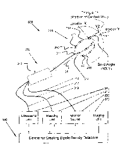
[00183] In various embodiments, the transducer can be selected from a
group
consisting of: ablation element; electrode; sound; and combinations of these.
[00184] In various embodiments, the second catheter elongate shaft can
comprise a
proximal portion with a proximal end and a distal portion with a distal end.
[00185] In various embodiments, the clamp assembly can comprise a
vibrational
transducer configured to emit ultrasound waves.
[00186] In various embodiments, the clamp assembly can comprise a clamping
mechanism constructed and arranged to be removably attached to the second
catheter
elongate shaft.
[00187] In various embodiments, the clamp assembly can be positioned on
the
proximal portion of the second catheter elongate shaft.
[00188] In various embodiments, the second catheter can comprise a handle.
[00189] In various embodiments, the clamp assembly can be positioned
within 10
centimeters from the handle.
[00190] In various embodiments, the second catheter elongate shaft can
further
comprise a conduit constructed and arranged to transmit the ultrasound waves
from the
proximal portion to the distal portion of the second catheter elongate shaft.
[00191] In various embodiments, the clamp assembly can be positioned on
the distal
portion of the second catheter elongate shaft.
[00192] In various embodiments, the second catheter distal portion can be
within 10
centimeters from the distal end of the second catheter elongate shaft.
22
CA 02829626 2013-09-09
WO 2012/122517
PCT/US2012/028593
[00193] In various embodiments, the second catheter elongate shaft can
further
comprise multiple electrodes wherein the multiple electrodes are positioned on
the distal end
of the second catheter elongate shaft and the clamp assembly is constructed
and arranged to
vibrate the multiple electrodes.
[00194] In various embodiments, the multiple electrodes can comprise the
multiple
electrodes described above.
[00195] In various embodiments, the second catheter elongate shaft can
further
comprise at least one thermocouple positioned on the second catheter elongate
shaft wherein
the clamp assembly is constructed and arranged to vibrate the at least one
thermocouple.
[00196] In various embodiments, the second catheter elongate shaft can
further
comprise at least one support arm attached to the second catheter elongate
shaft wherein the
clamp assembly is constructed and arranged to vibrate the at least one support
ann.
[00197] In various embodiments, the at least one support aim can comprise
at least one
of a sensor or a transducer.
[00198] In various embodiments, the second catheter elongate shaft can
further
comprise at least one ablation element attached to the second catheter
elongate shaft wherein
the clamp assembly can be constructed and arranged to vibrate the at least one
ablation
element.
[00199] In various embodiments, the second catheter elongate shaft can
further
comprise at least one sensor attached to the second catheter elongate shaft
wherein the clamp
assembly can be constructed and arranged to vibrate the at least one sensor
where the sensor
is selected from the group consisting of: temperature; pressure; electrical
signal; electrode;
sound; and combinations of these.
[00200] In various embodiments, the second catheter elongate shaft can
further
comprise at least one transducer attached to the second catheter elongate
shaft wherein the
clamp assembly can be constructed and arranged to vibrate the at least one
transducer where
the transducer is selected from the group consisting of: ablation element;
electrode; sound;
and combinations of these.
[00201] In various embodiments, the second catheter elongate shaft can
further
comprise at least one ultrasound crystal positioned on the second catheter
elongate shaft
23
CA 02829626 2015-12-02
wherein the clamp assembly can be constructed and arranged to vibrate the at
least
one crystal.
[00202] In various embodiments, the clamp assembly can be constructed and
arranged
to vibrate the second catheter elongate shaft.
[00203] In various embodiments, the clamp assembly can be positioned such that
the
clamp assembly can be located outside the patient's body while the distal end
of the
second catheter elongate shaft is located within the patient's body.
[00203a] Accordingly, in one aspect the present invention resides in a device
for
creating a database of dipole densities d(y) and distance measurements at the
surface
of one or more cardiac chambers of a patient, said device comprising: a
multiple-arm
assembly, comprising: multiple electrodes; and one or more transducers/sensors
constructed and arranged to emit and record ultrasound signals
[00203b] In another aspect the present invention resides in a system for
creating a
database of dipole densities d(y) and distance measurements at the surface of
one or
more cardiac chambers of a patient, said system comprising: a device for
creating a
database of dipole densities d(y) at the surface of one or more cardiac
chambers of a
patient, comprising: multiple-arm assembly, comprising: multiple electrodes;
one or
more transducers/sensors constructed and arranged to both emit and record
ultrasound
signals; a first receiver configured to receive mapping information from the
multiple
electrodes, the mapping information received when the multiple electrodes are
placed
in the one or more cardiac chambers; a second receiver configured to receive
anatomical information from at least one imaging instrument comprising the one
or
more transducers/sensors and configured to produce a geometrical depiction of
the
one or more cardiac chambers; a dipole density module configured to generate
the
database of dipole densities d(y), wherein the dipole density module
determines a
dipole density for individual triangle shaped projections onto the cardiac
chamber
wall, where each triangle projection at a location y contributes th(x,y) times
the dipole
density d(y) to a potential V(x) at a point x, wherein 6)(x,y) is the solid
angle for that
triangle projection, and wherein: a) x represents a series of locations within
one or
more cardiac chambers; and b) V(x) is a measured potential at point x, said
measured
potential recorded by the multiple electrodes.
24
CA 02829626 2015-12-02
[00204] Provided is device, system, and/or method for real time, non-contact
imaging
and distance measurements using ultrasound for dipole density mapping, as well
as
methods for diagnosing tissue health, as depicted in the drawings included
herein.
BRIEF DESCRIPTION OF THE DRAWINGS
[00205] The accompanying drawings, which are incorporated in and constitute a
part
of this specification, illustrate various embodiments in accordance with the
present
invention, and together with the description, serve to explain the principles
of the
inventions.
[00206] Fig. 1 illustrates a schematic view of an embodiment of a device for
determining a database table of dipole densities d(y) of at least one heart
chamber,
consistent with aspects of the present invention.
[00207] Fig. 2 illustrates a flow chart of an embodiment of a preferred method
for
determining a database table of dipole densities of at least one heart
chamber,
consistent with aspects of the present invention.
[00208] Fig. 3 illustrates a schematic view of an embodiment of a system for
determining a database table of dipole densities of at least one heart chamber
with
help of the solid angle 6(x,y) consistent with aspects of the present
invention.
[00209] Fig. 4 illustrates a side view of an end portion of a catheter
comprising
ultrasound elements attached to multiple support arms, consistent with aspects
of the
present invention.
[00210] Fig. 5 illustrates a side view of a system including a mapping
catheter
comprising multiple sensors, an ablation catheter comprising multiple ablation
elements and a clamping assembly attached to the ablation catheter, consistent
with
aspects of the present invention.
24a
CA 02829626 2013-09-09
WO 2012/122517
PCT/US2012/028593
[00211] Fig. 6 illustrates a flow chart of an embodiment of a preferred
method for
diagnosing the tissue of a patient, consistent with aspects of the present
invention.
DETAILED DESCRIPTION
[00212] A device for calculating surface charge densities has been
described in detail
in PCT International Application Number PCT/CH2007/000380 (hereinafter the
'380 patent
application), filed Aug. 3, 2007, and entitled METHOD AND DEVICE FOR
DETERMINING AND PRESENTING SURFACE CHARGE AND DIPOLE DENSITIES
ON CARDIAC WALLS.
[00213] As discussed in the '380 patent application, research indicated
that the use of
the surface charge densities (i.e. their distribution) or dipole densities
(i.e. their distribution)
to generate distribution map(s) would lead to more detailed and precise
infolination on
electric ionic activity of local cardiac cells than potentials. Surface charge
density or dipole
densities represent precise and sharp information of the electric activity
with a good spatial
resolution, whereas potentials resulting from integration of charge densities
provide only a
diffuse picture of electric activity. The electric nature of cardiac cell
membranes comprising
ionic charges of proteins and soluble ions can be precisely described by
surface charge and
dipole densities. The surface charge densities or dipole densities cannot be
directly measured
in the heart, but instead must be mathematically and accurately calculated
starting from
measured potentials. In other words, the information of voltage maps obtained
by current
mapping systems can be greatly refined when calculating surface charge
densities or dipole
densities from these.
[00214] The surface charge density means surface charge (Coulombs) per
unit area
(cm2). A dipole, as such, is a neutral element, wherein a part comprises a
positive charge and
the other part comprises the same but negative charge. A dipole might
represent the electric
nature of cellular membranes better, because in biological environment ion
charges are not
macroscopically separated.
[00215] In order to generate a map of surface charge densities (surface
charge density
distribution) according to the '380 patent application, the geometry of the
given heart
chamber must be known. The 3D geometry of the cardiac chamber is typically
assessed by
CA 02829626 2013-09-09
WO 2012/122517
PCT/US2012/028593
currently available and common mapping systems (so-called locator systems) or,
alternatively, by integrating anatomical data from CT/MRI scans. For the
measurement of
potentials the non-contact mapping method a probe electrode was used. The
probe electrode
may be a multi-electrode array with elliptic or spherical shape. The spherical
shape has
certain advantages for the subsequent data analysis. But also other types or
even several
independent electrodes could be used to measure Ve. For example, when
considering the
ventricular cavity within the endocardium and taking a probe electrode with a
surface Sp,
which is located in the blood, it is possible to measure the potential
V(x,y,z) at point x,y,z on
the surface Sp. In order to calculate the potential at the endocardial surface
Se the Laplace
equation:
a2 a2 a2
AV=( + ____________________________________ )V =0
ax 2 ay 2 8z2 ( )
needs to be solved, wherein V is the potential and x,y,z denote the three
dimensional
coordinates. The boundary conditions for this equation are V(x,y,z) =
Vp(x,y,z) on Sp,
wherein Vp is the potential on surface of the probe.
[00216] The solution is an integral that allows for calculating the
potential V(x'y'z') at
any point x'y'z' in the whole volume of the heart chamber that is filled with
blood. For
calculating said integral numerically a discretisation of the cardiac surface
is necessary and
the so called boundary element method (BEM) has to be used.
[00217] The boundary element method is a numerical computational method
for
solving linear integral equations (i.e. in surface integral form). The method
was applied in
many areas of engineering and science including fluid mechanics, acoustics,
electromagnetics, and fracture mechanics.
[00218] The boundary element method is often more efficient than other
methods,
including the finite element method. Boundary element formulations typically
give rise to
fully populated matrices after discretisation. This means, that the storage
requirements and
computational time will tend to grow according to the square of the problem
size. By
contrast, finite element matrices are typically banded (elements are only
locally connected)
26
CA 02829626 2013-09-09
WO 2012/122517 PCT/US2012/028593
and the storage requirements for the system matrices typically grow quite
linearly with the
problem size.
[00219] With the above in mind, all potentials Vp (x 1 'yl 'z 1 ') on the
surface of the
probe can be measured. To calculate the potential V, on the wall of the heart
chamber, the
known geometry of the surface of the heart chamber must be divided in discrete
parts to use
the boundary element method. The endocardial potentials V, are then given by a
linear
matrix transformation T from the probe potentials Vp : V, = T V.
[00220] After measuring and calculating one or more electric potential(s)
V, of cardiac
cells in one or more position(s) P(x,y,z) of the at least one given heart
chamber at a given
time t. The surface charge density and the dipole density are related to
potential according to
the following two Poisson equations:
LW = p(P)g s,(P) (2)
AV, = _____________________________ (vgs,(P)) (3)
wherein p(P) is the surface charge density in position P=x,y,z, S (P) is the
delta-distribution
concentrated on the surface of the heart chamber Se and v is the dipole
density.
[00221] There is a well known relationship between the potential V, on the
surface of
the wall of the heart chamber and the surface charge (4) or dipole densities
(5).
____________________________________ da(P') V,(P) = 1 p(P') (4)
47r j P¨P
se
V e(P) -- 1 f a 1 v(P1) da(P') (5)
42t Se
(For a review see Jackson JD. Classical Electrodynamics, 2nd edition, Wiley,
New York
1975.)
[00222] The boundary element method again provides a code for transforming
the
potential Vein formulas 4 and 5 into the desired surface charge densities and
dipole densities,
which can be recorded in the database.
27
CA 02829626 2013-09-09
WO 2012/122517 PCT/US2012/028593
[00223] In another embodiment of the method, the electric potential(s) Ve
is (are)
determined by contact mapping. In this case the steps for calculating the
electric potential Ve
are not necessary, because the direct contact of the electrode to the wall of
the heart chamber
already provides the electric potential V,.
[00224] In a preferred embodiment, the probe electrode comprises a shape
that allows
for calculating precisely the electric potential Ve and, thus, simplifies the
calculations for
transforming V, into the desired charge or dipole densities. This preferred
geometry of the
electrode is essentially ellipsoidal or spherical.
[00225] In order to employ the method for determining a database table of
surface
charge densities of at least one given heart chamber in the context of the
'380 patent
application, it was preferred to use a system comprising at least:
a) one unit for measuring and recording electric potentials V at a given
position
P(x,y,z) on the surface of a given heart chamber (Contact mapping) or a probe
electrode positioned within the heart, but without direct wall contact
(noncontact mapping)
b) one A/D-converter for converting the measured electric potentials into
digital
data,
c) one memory to save the measured and/or transformed data, and
d) one processor unit for transforming the digital data into digital
surface charge
density or dipole density data.
[00226] It is noted that numerous devices for localising and determining
electric
potentials of cardiac cells in a given heart chamber by invasive and non-
invasive methods are
well known in the art and have been employed by medical practitioners over
many years.
Hence, the method, system, and devices of the '380 patent application did not
require any
particular new electrodes for implementing the best mode for practicing the
invention.
Instead, the '380 patent application provided a new and advantageous
processing of the
available data that will allow for an increase in precision, accuracy and
spatial resolution of
cardiac activation mapping when compared to prior art systems based on
electric surface
potentials in the heart only. The systems and methods of the '380 patent
application would
also allow for providing superior diagnostic means for diagnosing cardiac
arrhythmias and
electric status of heart cells including metabolic and functional information.
28
CA 02829626 2013-09-09
WO 2012/122517
PCT/US2012/028593
[00227] The present invention provides an improved device, system and
method for
calculating and visualizing the distribution and activity of dipole charge
densities on a cardiac
wall. The dipole densities are directly determined geometrically, avoiding the
errors
encountered using previous extrapolation algorithms.
[00228] In one embodiment, the device of the present invention comprises
multiple
electrodes located on one or more catheters, a transducer, and a sensor. The
device may be
used to create a three dimensional database of dipole densities d(y) and
distance
measurements at the surface of one or more cardiac chambers of a patient. The
distance
measurements may include but are not limited to: the distance between at least
one of the
multiple electrodes and the heart wall, the distance between at least one of
the multiple
electrodes and the transducer and/or sensor, and the distance between the
heart wall and the
transducer and/or sensor. The distance measurements may be calculated by
analyzing the
sensor recorded angle and/or the sensor frequency changes. The device may also
be
configured to produce continuous, real time images of the tissue of a patient.
Examples of
images may include, but are not limited to: one more cardiac chambers, a
cardiac wall, the
tissue proximate at least one of the multiple electrodes, at least one of the
multiple electrodes,
and combinations of these. The device may provide one or more of: tissue image
information
such as tissue position, tissue thickness (e.g. cardiac wall thickness) and
tissue motion (e.g.
cardiac wall motion) information; distance information such as distance
between two tissue
locations, distance between a tissue location and a device component location,
and distance
between two device component locations; tissue electrical activity
information; status of
ablation of a portion of tissue; and combinations of these.
[00229] The present invention incorporates a transducer and a sensor, each
preferably
ultrasonic and contained in a single component. The transducer and sensor are
configured to
determine a non-contact measurement of the distance or presence of one or more
targets such
as tissue of a patient or a component of one or more catheters or other
devices. Information
is produced by transmitting an ultrasound wave followed by measuring the time
required for
the sound echo to return to and be sensed by the sensor, thus determining the
distance
between all reflected surfaces and the sensor/transmitter. This additional
information enables
a more precise dipole density d(y) measurement. Measurements may be taken to
determine
29
CA 02829626 2013-09-09
WO 2012/122517 PCT/US2012/028593
the thickness of an object, such as the thickness of cardiac tissue, which may
be used to
deteiiiiine an ablation parameter such as power or time of energy delivery.
[00230] Utilizing the present invention, a method for diagnosing tissue is
also
disclosed. Analyzing the information gathered from a catheter device,
specifically the tissue
movement and the tissue's electrical charge, a clinician is able to determine
the health of the
tissue. For example, if adequate tissue movement has been detected, and the
tissue produces
an electrical signal indicative of a healthy state, then the tissue is
determined to be healthy.
With the tissue diagnosis, a clinician may deteunine what type of treatment,
e.g. ablation, is
favorable to the patient.
[00231] In accordance with the present invention, provided is a device
that measures
and calculates a database of dipole densities d(y) on the cardiac wall. The
actual measured
potentials in the heart result from electrical activity of cells, which can be
regarded as
dipoles. The dipoles consist of ion charges on both sides of biological
membranes. The use
of dipole densities offers a precise representation of the electrical
activity. Systems and
methods in accordance with the present invention efficiently and effectively
calculate the
dipole densities utilizing one or more mathematical theorems. This calculation
is
significantly more precise than calculations of virtual potentials produced by
current systems,
which lose spatial precision because of the required numerical methods and the
use of
potentials instead of dipole densities. Systems and methods in accordance with
the present
invention are efficient in calculating dipole densities geometrically, such as
through the use
of computer systems, or similar microcontroller and/or mathematical processing
equipment.
[00232] Definitions. To facilitate an understanding of the invention, a
number of temis
are defined below.
[00233] As used herein, the terms "subject" and "patient" refer to any
animal, such as a
mammal like livestock, pets, and preferably a human. Specific examples of
"subjects" and
"patients" include, but are not limited to, individuals requiring medical
assistance, and in
particular, patients with an arrhythmia such as atrial fibrillation (AF).
[00234] As used herein, in the illustrative embodiments, the term "solid
angle" is the
two-dimensional angle subtended in the three dimensional space between a
triangle on the
heart wall and the position x of observation. When viewed from location x,
straight lines are
drawn from point x to the vertices of the triangle, and a sphere is
constructed of radius r---1
CA 02829626 2013-09-09
WO 2012/122517
PCT/US2012/028593
with center of x. The straight lines then define a triangular section on the
surface of the unit
sphere. The solid angle is equal to the surface area of that triangle. As used
herein, in the
illustrative embodiments, the term "dipole density" refers to a three
dimensional table of
density magnitudes and d(y) generally refers to three dimensional system or
space.
[00235] The methods and devices of the present invention have advantages
over
previous prior art devices. Figs. 1-6 illustrate various preferred embodiments
of devices,
systems and methods in accordance with aspects of the present invention.
However, the
present invention is not limited to these particular configurations.
[00236] Referring now to Fig. 1, a schematic view of an embodiment of a
device for
determining a database table of dipole densities of at least one heart chamber
of a patient is
illustrated. Device 100 includes a first receiver 110 configured to receive
electrical potentials
from a separate device, such as a device including a multi-electrode mapping
catheter placed
in the circulating blood within a chamber of the patient's heart. Device 100
further includes a
second receiver 120 configured to receive cardiac geometry information (e.g.
the geometric
contour of the cardiac chamber wall), such as from an instrument including,
but not limited
to: Computed Tomography; MRI; Ultrasound; a multi-electrode mapping catheter;
and
combinations of these. Alternatively, a standard geometry can be loaded
representing a
model of the cardiac chamber.
[00237] Device 100 further comprises a third receiver 140 configured
receive
ultrasound information from ultrasound unit 240. Ultrasound unit 240 comprises
a transducer
and sensor. In a preferred embodiment, the transducer comprises an ultrasound
transducer
configured to produce high frequency vibrations, i.e., ultrasound waves, in a
pulsed or
constant manner. Typically, the ultrasound transducer produces sound waves
having a
wavelength of 5 ¨ 15MHz. In some embodiments, the transducer and the sensor
are a single
component such as a piezo crystal configured to both transmit and sense
ultrasound signals.
[00238] In this embodiment, the sensor is preferably an ultrasound sensor
configured
to record or otherwise detect the emitted ultrasound waves from the ultrasound
transducer.
The sensor may be further configured to determine real-time continuous
measurements of the
position of at least one of the multiple electrodes and/or the sensor within
the cardiac
chamber. Knowing the speed of sound in the particular environment, as well as
the timing of
31
CA 02829626 2013-09-09
WO 2012/122517 PCT/US2012/028593
the delivery of sound waves by the transducer, the distance between the
sensor, transducer
and one or more reflected surfaces can be calculated.
[00239] In a typical embodiment, a piezo crystal transmits ultrasound
waves and
receives the reflections of those waves. As is well known to those of skill in
the art, the
timing between transmitting and receiving can be used to deteiinine locations
of the reflective
surfaces such as tissue surfaces and device component surfaces. In one
embodiment, precise
locations and measurements of target cardiac tissue is determined, resulting
in a more precise
and effective therapy. The ultrasound crystal will transmit a signal that is
reflected off of
tissue surfaces, which can be used to determine the distance from the mapping
electrode to
the tissue. This distance will be fed into the software algorithm to aid in
the calculation of
electrical activity via dipole density or direct electrical signal analysis.
[00240] By having the precise distance, the overall calculations will be
very precise
(frequency; it is approximately 3 megahertz and may be up to the 18
megahertz). The
emitted waves may be at constant frequency or produced by a chip of changing
frequency (to
allow pulse compression on reception). The precision in dipole density
calculations along
with the distance measurement will allow for the precise detailing of the
cardiac cells in the
electrical activity and will allow for the precise identification of cell
activity to identify which
cells are the earliest sites of activation. In one embodiment, the sensor may
be configured to
automatically detect the distance from the sensor to the cardiac wall via a
first reflection and
detect the wall thickness via a second reflection. Other distances
measurements include, but
are not limited to: the distance between at least one of the multiple
electrodes and the heart
wall, the distance between at least one of the multiple electrodes and the
transducer and/or
sensor, and the distance between the heart wall and the transducer and/or
sensor. In another
embodiment, the ultrasonic element integrates multiple reflections to
construct a complete
image including wall distance and thickness. In yet another embodiment, the
ultrasonic
element provides information relative to the positioning of the cardiac tissue
and one or more
electrodes, such as to localize an ablation and/or a mapping catheter
including those one or
more electrodes.
[00241] In one embodiment, the sensor and/or transducer includes at least
one crystal,
typically comprised of a piezoelectric material, which is positioned proximate
to the center of
each electrode within an electrode array. In another embodiment, the crystal
is positioned
32
CA 02829626 2013-09-09
WO 2012/122517
PCT/US2012/028593
between two or more electrodes, such as to create a device with a ratio of
mapping electrodes
to crystals of 1:1, 2:1, 5:2, 3:1, 4:1 or another ratio. The at least one
crystal may be
constructed and arranged to receive the signals transmitted by an ultrasound
transducer,
and/or the reflections of those signals. The at least one crystal may be in a
fixed position or
may be rotated via a rotating mechanism such as by a rotating shaft operably
attached to the
at least one ultrasound crystal. The rotation may be a full rotation, e.g.
3600, such that the
full circumference of the cardiac chamber is measured. Alternatively, the
rotation of the at
least one crystal may be partial. Alternatively or additionally, one or more
ultrasound
crystals may be moved axially, such as in a reciprocating motion to produce an
image of an
increased length and/or to produce a 3-D reconstructed image. In another
embodiment, the
sensor and/or transducer comprise a plurality of crystals arranged in an
array, for example, a
circumferential array.
[00242] In another embodiment, the ultrasound sensor and/or transducer may
comprise
a probe operably attached to the catheter and configured to vibrate one or
more catheter
components. In an alternate embodiment, the ultrasound sensor and/or
transducer comprise a
piezoelectric film covering each electrode within the array. In yet another
embodiment, the
ultrasound sensor and/or transducer comprise a piezoelectric cable operably
connected to
each electrode.
[00243] The ultrasound sensor and/or transducer may be housed within a
mechanical
clamping assembly which may be attached to the shaft of a catheter, such as a
mapping
catheter or an ablation catheter. Additionally, a particular clamping assembly
with a
particular ultrasound frequency may be used with a particular catheter, while
a second
clamping assembly with a second ultrasound frequency may be used with a second
catheter.
In another embodiment, the ultrasound sensor and/or transducer may be directly
inserted into
the mapping catheter.
[00244] In yet another embodiment, the device may comprise a multiple arm
assembly
such that the sensor and/or transducer are mounted to the multiple arm
assembly.
Additionally, at least one electrode may be mounted to the multiple arm
assembly. In an
alternate embodiment, the sensor and/or transducer may be constructed as part
of the
electrode. For example, the device may comprise a sensor/electrode
combination. In another
embodiment, the sensor and/or transducer may be constructed as a forward
facing sensor and
33
CA 02829626 2013-09-09
WO 2012/122517 PCT/US2012/028593
arranged to project a signal directly in line with an electrode to the tissue.
In yet another
embodiment, the sensor and/or transducer may be configured to be rotated such
that the
sensor and/or transducer is facing each electrode individually, and a signal
may be emitted
past each electrode.
[00245] In some embodiments, the device is constructed and arranged to be
steered
such that the distal end of the device is positioned in approximately the
geometric center of
the heart chamber of a patient. In this embodiment, the catheter may be loaded
into a
delivery system, e.g., a delivery sheath and may be advanced from the delivery
sheath such
that the dipole density mapping system comprising the ultrasound sensor is
located in the
blood and the heart chamber. Also in this embodiment, the delivery sheath may
comprise a
central lumen configured to slidingly receive an ablation catheter. This
configuration of the
device may allow a user to perform a diagnostic procedure with one device.
Additionally,
only one trans-septal crossing may be necessary. In yet another embodiment,
the device may
be steerable. For example, a user may determine the ablation site via real-
time tissue analysis
and imaging, and subsequently the device may be steered to the desired
location. Steering of
the device may be achieved via cables which may be housed in a lumen of a
delivery sheath
similar to the delivery sheath described above.
[00246] Device 100 further includes a dipole density module 130 which
comprises
mathematical processing element, such as a computer or other electronic module
including
software and/or hardware for performing mathematical or other calculations.
Dipole density
module 130 receives mapping information from first receiver 110 and cardiac
geometry
information from second receiver 120. Dipole density module 130 preferably
uses one or
more algorithms to process the received mapping and geometry information to
produce a
database table of dipole densities, e.g., a three dimensional database table
of dipole densities.
[00247] The geometrical model of the cardiac chamber is processed by
dipole density
module 130 into multiple small triangles (triangularization). When the
triangles are
sufficiently small, the dipole density at each triangle can be regarded as
constant. In a
preferred embodiment, a standard cardiac chamber of 4-6 cm diameter is divided
up into over
1000 triangles. In another preferred embodiment, the number of triangles
determined by
dipole density module 130 is based on the size of the heart chamber. With the
electrodes
positioned in a cardiac chamber by a clinician, such as an
electrophysiologist, the potentials
34
CA 02829626 2013-09-09
WO 2012/122517
PCT/US2012/028593
at each electrode are recorded. Each triangle is seen by the corresponding
electrode under a
certain solid angle. The dipole density module 130 computes the solid angle
th(x,y)
subtended by each triangle at position y on each electrode at position x on
the multi-electrode
catheter. If the dipole density at the triangle is d(y), the triangle
contributes th(x,y) times d(y)
to the potential V(x) at the position x on the multi-electrode catheter. The
total measured
potential V(x) is the sum resulting from all the triangles. A detailed
description is provided
in reference to FIG. 3 herebelow.
[00248] In a preferred embodiment, dipole density module 130 implements a
progressive algorithm that can be modified and/or refined in order to improve
spatial and/or
time resolution of the database of dipole densities that are produced. The
dipole densities
d(y) are obtained by solving a linear system of equations. This calculation
requires some care
to avoid numerical instabilities. Thereby a map of dipole densities can be
created at each
corresponding time interval. The synthesis of the maps generates a cascade of
the activation
sequence of each corresponding heart beat that can be used to define the
origin of the
electrical activity, arrhythmias or diagnose cardiac disease.
[00249] The measuring electrodes used in the present invention are placed
in the blood
flow in a heart chamber, a relatively homogeneous condition, such that the
mathematical
analysis of the present invention is well applicable. In a preferred
embodiment, skin
electrodes are also implemented such that dipole density module 130 can use
the information
received from the skin electrodes to calculate and/or recalculate the dipole
densities for the
cardiac wall. The spatial resolution which can be obtained by invasive (i.e.,
placed in the
heart chamber) multi-electrode potential measurements is limited by the number
of electrodes
that can be placed in any cardiac chamber, such as the Left Atrium (LA). Skin
placed
electrodes, such as electrodes placed on the thorax, are not as space limited.
However, due
mainly to the inhomogeneous structure of the body, it is difficult to localize
the actual sources
of the skin electrode measured potentials. A highly complicated boundary value
problem
must be solved with boundary conditions that are poorly known, and previous
attempts at
determining the "action potential" from body surface ECG (alone) have not been
very
successful.
[00250] The badly defined boundary value problem can be avoided by an
additional
measurement (in addition to the skin electrode measurements) of the multi-
electrode array of
CA 02829626 2013-09-09
WO 2012/122517
PCT/US2012/028593
the present invention. A small sinusoidal voltage Vi is applied to each
electrode 1=1, . . . L on
the electrode array in the heart, and the resulting voltages Wk, k=1, . . . .
K is measured at the
surface electrodes. This yields the KXL transition matrix AkI
Wk = EAkIVI
z=i (6)
[00251] Calculating solid angles produces the linear transformation B111
between the
electrode array potentials V, and the dipole densities dõ, n=1, . . . N of N
regions of the heart
wall:
Liz = Stn
n=1 (7)
N is chosen to be N=K+L where K is the number of surface electrodes and L is
the number of
internally placed array electrodes. Substituting equation (7) into (6) we
have:
L N
Wk = yxAk2Bindn
n=1. (8)
[00252] Therefore, by simultaneous measuring of the potentials of the
cardiac activity
with all K+L electrodes, N=K+L dipole densities of N regions on the heart wall
can be
calculated. This method yields a higher spatial resolution than the L array
electrodes alone.
In the solution of the linear system of equations (7) + (8), regularization
techniques must be
used (e.g. Tikhonov regularization and its modifications) in order to avoid
numerical
instabilities.
[00253] Referring now to Fig. 2, an embodiment of a preferred method for
determining
a database table of dipole densities of at least one heart chamber of a
patient is illustrated. In
Step 10, a multi-electrode array is placed within the corresponding heart
chamber. In Step
20, the geometry of the corresponding heart chamber may be obtained in
relation to the multi-
electrode array position via an ultrasound transducer and sensor, typically a
single ultrasound
crystal configured to both emit and record ultrasound signals. In addition to
chamber
geometry, magnitude and other properties of wall motion of cardiac wall tissue
can be
36
CA 02829626 2013-09-09
WO 2012/122517
PCT/US2012/028593
determined. For example, an ultrasound transducer positioned on a distal
portion of the
catheter is configured to transmit ultrasound waves to the wall of the cardiac
chamber as well
as to components of one or more devices within the cardiac chamber. In an
alternative
embodiment, an ultrasound transducer is attached to a proximal portion of a
catheter shaft
and configured to vibrate the shaft or one or more components mounted to the
shaft, thus
sending ultrasound waves to the wall of the cardiac chamber. One or more
ultrasound
sensors detect reflections of the transmitted ultrasound. In addition, the
thickness of a
patient's tissue as well as the motion of the tissue may be determined, such
as to enable a
clinician to determine what treatment, (e.g., what ablation parameters) is
appropriate for a
patient. A detailed description of one embodiment of the ultrasound transducer
and sensor
that can be utilized in this step is described in Fig. 1 hereabove.
Alternatively or additionally,
the geometry of the corresponding heart chamber is obtained in relation to the
multi-electrode
array position, such as by moving around a second mapping electrode or by
importing a
geometry model from an imaging study (e.g., using computed tomography, MRI or
ultrasound before or after the multi-electrode array of electrodes has been
placed in the heart
chamber). The surface of the geometry of the corresponding heart chamber is
divided into
small triangles, typically at least 1000 small triangles.
[00254] In Step 30, the dipole density d(y) can be calculated from the
measured
potential values and the calculated solid angles. The measurements can be
repeated
successively during the cardiac cycle giving a high time-resolution during
each millisecond.
The information of the timely dependent dipole densities can be depicted as an
activation
map of the corresponding heart chamber for the given heart beat. The
information can be
used to diagnose and/or treat a patient with a cardiac arrhythmia, such as
atrial fibrillation.
[00255] In a preferred embodiment, the information is used to determine
cardiac wall
treatment locations for lesion creation, such as a lesion created in the Left
or Right atrium, by
an RF, ultrasound or cryogenic ablation catheter. In another preferred
embodiment, the
multiple electrode mapping array is placed in a ventricle and the dipole
densities are
detennined for the ventricular wall, such as to detect ischemia or quantify
myocardial
function.
[00256] In one embodiment, the device includes one or more catheters
constructed and
arranged to be steered such that the distal end of the catheter can be
positioned in
37
CA 02829626 2013-09-09
WO 2012/122517 PCT/US2012/028593
approximately the geometric center of the heart chamber of a patient. In this
method, a
mapping catheter may be loaded into a delivery system (e.g. a delivery sheath)
and may be
advanced from the delivery system such that the dipole density mapping system
comprising
an ultrasound sensor and transducer is located in the circulating blood of the
heart chamber.
[00257] Referring now to Fig. 3, an embodiment of a system for determining
a
database table of dipole densities of at least one heart chamber of a patient
is illustrated.
System 500 includes device 100, which is configured to create a database table
of three
dimensional dipole densities d(y) based on voltage potential measurements
within the heart
chamber and image information relating to the heart chamber, as has been
described
hereabove. System 500 further includes imaging unit 220, which is configured
to provide a
two or three-dimensional image of the heart chamber to device 100. Imaging
unit 220 may
perform at least one of Computed Tomography, MRI and/or ultrasound imaging.
Imaging
unit 220 may produce any form of real or virtual models of the cardiac
chambers, such that a
triangularization analysis is possible.
[00258] System 500 further includes mapping catheter 310, which includes
shaft 311,
shown inserted into a chamber of a patient's heart, such as the Left Atrium
(LA). At the distal
end of shaft 311 is an electrode array 315 including multiple electrodes 316.
Electrode array
315 is shown in a basket construction, comprising support arms 314, but
numerous other
constructions can be used including multiple independent arms, spiral arrays,
electrode
covered balloons, and other constructions configured to place multiple
electrodes into a three-
dimensional space. In a preferred embodiment, any catheter with a three-
dimensional array
of electrodes can be used to supply the mapping information to device 100.
[00259] In this embodiment, electrodes 316 are connected to wires, not
shown, but
traveling proximally to cable 317, which is electrically connected to a
mapping unit 210, such
as an electrocardiogram (ECG) unit. Mapping unit 210 includes a monitor for
displaying
information, such as the potentials recorded by electrodes 316, as well as the
dipole density
information produced by device 100. In an alternative embodiment, device 100
further
includes a monitor, not shown, but configured to display one or more of:
dipole density
information; potentials recorded by electrodes 316; and cardiac chamber
contours and other
geometry information. In a preferred embodiment, dipole density and or
recorded potentials
information is shown in reference to a three-dimensional representation of the
heart chamber
38
CA 02829626 2013-09-09
WO 2012/122517 PCT/US2012/028593
into which catheter 310 is inserted. In an alternative embodiment, imaging
unit 220 may
include a device configured to create an image of the cardiac chamber from
signals recorded
from an electrode catheter, such as catheter 310.
[00260] System 500 may include a device for treating a cardiac arrhythmia,
such as
ablation source 230, which is electrically attached to electrodes 316 via
cable 318.
Alternatively or additionally, ablation source 230 can be attached to a
different ablation
catheter, such as a single or multiple ablation element catheter configured to
deliver ablation
energy such as RF energy, cryogenic energy, or other tissue disrupting energy.
[00261] System 500 may further comprise ultrasound unit 240, which is
operably
connected to ultrasound sensor, crystal 340 via cable 319. Unit 240 includes
ultrasound
transducer 341, an operably attachable clamping assembly configured to be
placed around the
shaft of a catheter device and cause one or more components of the catheter
device to
transmit ultrasound waves, such as waves configured to reflect off one or more
structures and
be recorded by crystal 340. Unit 240 processes the measurement data obtained
by crystal 340
(i.e. the reflections recorded by crystal 340) and forwards the data to device
100.
Measurement data may include the position of crystal 340 relative to the
cardiac chamber and
the electrodes 316, as has been described in detail in reference to Fig. 1
hereabove.
[00262] As shown in Fig. 3, triangle Ti, defined by device 100 is at
location Y.
Electrode 316a of catheter 310 is at location X. The geometric relationship
between triangle
Ti and Location X is defined by the solid angle, angle co(X,Y). Device 100
includes dipole
density module 130, as shown in Fig. 1, such that each triangle at location y
contributes
th(x,y) times the dipole density d(y) to the potential V(x) at the position x
on a multi-
electrode. Solid angle 6(x,y), as defined above, corresponds to the triangle
at a location y and
the electrode at positions x on the multi-electrode array. The dipole density
module 130, as
shown in Fig. 1, of device 100 determines from the total measured potential
V(x), which is
the sum resulting from all the triangles defined by device 100, the desired
dipole density d(y).
[00263] When sufficient potentials values V(x) are measured (e.g. from 10
to 10,000
with increasing number of measured potentials providing more accurate
results), the dipole
density d(y) at many equally distributed regions y on the cardiac wall is
calculated by solving
a linear equation system. By interpolation of the measured potentials (e.g.
with help of
splines) their number can be increased to a higher number of regions. The
solid angle co(x,y)
39
CA 02829626 2013-09-09
WO 2012/122517 PCT/US2012/028593
of a region is the sum of the solid angles of the individual triangles in the
region on the
cardiac wall. This calculation of dipole density results, such as via an
automatic computer
program foiiiiing at least part of dipole density module 130, as shown in Fig.
1.
[00264] In a preferred embodiment, the results are presented in a visual,
anatomical
format, such as depicting the dipole densities on a geometric image of the
cardiac wall in
relation to time (t). This format allows a clinician, such as an
electrophysiologist, to
determine the activation sequence, or other electrical and mechanical
measures, on the
cardiac wall, such as to determine treatment locations for a cardiac
arrhythmia or other
inadequacy in cardiac tissue health, such as force of tissue contraction and
motion of the
chamber wall. The results may be shown on a display of mapping unit 210, or on
a separate
unit such as a display included with device 100, display not shown but
preferably a color
monitor. In a preferred embodiment, the device of the present invention is
implemented as,
or includes, a software program that is executable by at least one processor.
The software
program can be integrated into one or more of: an ECG system; a cardiac tissue
ablation
system; an imaging system; a computer; and combinations of these.
[00265] In a preferred embodiment, the multi-electrode catheter includes
at least ten
electrodes, configured to represent a three dimensional body with known
geometry. The
electrodes are preferably positioned in a spherical geometry, such as a
spherical geometry
created in a basket catheter, comprising support arms 314. Elliptical
electrode array
geometries may be used, such as those provided in the Ensite Array Catheter,
manufactured
by St. Jude Medical of St. Paul Minn. In an alternative embodiment, multiple
catheters are
inserted into the heart chamber to provide the multiple electrodes.
[00266] In an alternative embodiment, the electrodes of the multi-
electrode mapping
array are repositioned during the method of detelinining dipole densities.
Repositioning of
electrodes can be beneficial to increase the number of measured potential
values, if electrode
positions are known. Therefore, repositioning is in concordance with
adjustment of the
geometry map in relation to the multi-electrode mapping catheter.
[00267] Referring now to Fig. 4, a side view of a catheter comprising an
ultrasound
sensor configured to determine real-time continuous measurements of the
position of the
catheter within a cardiac chamber is illustrated. Catheter 310 comprises shaft
311 and array
315 positioned on the distal end of shaft 311. Array 315 comprises multiple
support arms
CA 02829626 2013-09-09
WO 2012/122517
PCT/US2012/028593
314 which include one or more electrodes 316 and one or more sensors,
ultrasound crystal
340. Each crystal 340 may be positioned on electrode 316, on a support aim of
array 315, or
at another catheter 310 location. In a preferred embodiment, crystal 340 is
located between
two electrodes 316 as shown, or in a center portion a single electrode 316.
[00268] Ultrasound crystal 340 is configured to detect ultrasound waves,
such as
ultrasound waves produced by ultrasound emitter 341, preferably a removable
clamping
assembly including emitter 341 and clamped to shaft 311 of mapping catheter
310 as is
described in detail in reference to Fig. 5 herebelow. Emitter 341 is
configured to produce
high frequency vibrations, i.e. ultrasound waves in a pulsed or constant
manner. One or more
sound emitting devices, such as devices configured to clamp to one or more
catheters, may be
used to transmit sound to one or more crystals 340. In one embodiment, a first
clamping
assembly with a particular ultrasound frequency may be used with a first
catheter, while a
second clamping assembly with a second ultrasound frequency may be used with a
second
catheter. In another embodiment, ultrasound sensor 340 is positioned on a
second elongate
shaft, not shown but configured to be inserted into mapping catheter 310, such
as through one
or more lumens, not shown, of mapping catheter 310. In a preferred embodiment,
one or
more crystals 340 may be configured to both record and transmit ultrasound
waves, such as to
avoid the need for emitter 341. Crystals 340 and electrodes 316 may be
provided in various
ratios, such as a ratio of two electrodes to one ultrasound crystal, such as
when each
ultrasound crystal 340 has an electrode 316 positioned at each end. In another
embodiment, a
ratio of five electrodes 316 to two crystals 340 is provided, such as a
catheter shaft including
sets of two assemblies with a single electrode 316 positioned in between. Each
assembly
includes an ultrasound crystal 340 with an electrode 316 positioned at each
end.
[00269] In an alternate embodiment, a drive shaft 320 is operably connected
to a
rotation mechanism, not shown but configured to rotate shaft 320 causing one
or more
crystals 340 to rotate within electrode 316 or another portion of catheter
310. As described in
reference to Fig. 1 hereabove, crystal 340 may rotate a full 360 or may
rotate through an arc
less than 360 . Alternatively, catheter 310 may comprise a plurality of
crystals 340 arranged
in an array, for example, a circumferential array surrounding shaft 311, one
or more
electrodes 316 and/or a support arm 314 of array 315, such as a phased array
of crystals
configured to produce a 360 ultrasound image, well known to those of skill in
the art.
41
CA 02829626 2013-09-09
WO 2012/122517 PCT/US2012/028593
[00270] In another embodiment, ultrasound sensor 340 comprises a probe,
not shown,
but typically a probe removably attached to or inserted within catheter 310.
In an alternate
embodiment, ultrasound sensor 340 comprises a piezoelectric film, not shown
but typically
covering one or more electrodes 316 within array 315. In yet another
embodiment, ultrasound
sensor 340 comprises a piezoelectric cable, not shown but operably connected
to one or more
electrodes 316.
[00271] Referring now to Fig. 5, a side view of a system including a
mapping catheter
comprising a sensor and an ablation catheter comprising a transducer is
illustrated. System
500 comprises mapping catheter 310 and ablation catheter 400. Mapping catheter
310
comprises shaft 311 including array 315 on its distal end. Array 315 includes
one or more
electrodes 316 mounted to one or more arms 314, each electrode configured to
record cellular
activity in tissue. Array 315 further includes one or more ultrasound emitting
crystals 340,
each positioned between two electrodes 316. Crystals 340 may be configured to
both record
and transmit ultrasound waves.
[00272] Ablation catheter 400 comprises shaft 401, having a proximal
portion with a
proximal end and a distal portion with a distal end, and clamping assembly
410. Clamping
assembly 410 is shown positioned on shaft 401 proximate handle 402, i.e. the
proximal
portion of shaft 401, such as at a location 10cm from the proximal end of
shaft 401.
Clamping assembly 410 comprises ultrasound transducer 412 and clamping
mechanism 411
configured to removably attach clamping assembly 410 to shaft 401 of catheter
400.
Additionally, ablation catheter 400 comprises multiple ablation elements,
electrodes 420,
located on the distal end of shaft 401 and configured to deliver ablation
energy (e.g. RF
energy) and also to receive the ultrasound vibrations produced by clamping
assembly 410 and
ultrasound transducer 412. In turn, electrodes 420, and one or more other
components of
ablation catheter 400, emit ultrasounds waves. The emitted ultrasound waves
are received by
ultrasound crystals 340 of catheter 310, and can be used to produce position
information
relative to one or more components of ablation catheter 400 and/or mapping
catheter 310.
Clamping assembly 410 is configured to produce high frequency vibrations, i.e.
ultrasound
waves in a pulsed or constant manner, typically with a frequency between 5 and
18 MHz. In
another embodiment, ablation catheter 400 may include a conduit, not shown but
typically a
42
CA 02829626 2013-09-09
WO 2012/122517 PCT/US2012/028593
solid or hollow tube configured to transmit the ultrasound waves from the
proximal portion to
the distal portion of ablation catheter 400.
[00273] In an alternate embodiment, one or more support arms, not shown,
may be
attached to ablation catheter 400 (e.g. similar to the support arms 314 of
array 315 of catheter
310), and electrodes 420 may be located on the one or more support aims. The
support arms
may be radially distributed about ablation catheter 400 and may comprise
various geometric
shapes, e.g. circular or rectangular. In this embodiment, clamping assembly
410 may be
constructed and arranged to vibrate the one or more support arms, in turn
vibrating the one or
more electrodes, thus transmitting ultrasound waves to sensors 340. In another
embodiment,
electrodes 420 may be configured to record electrical activity in cells as
well as deliver
ablation energy.
[00274] In one embodiment, catheter 400 may further include one or more
sensors, not
shown but typically including one or more sensors selected from the group
consisting of: a
temperature sensor, such as a thermocouple; a pressure sensor; an acoustic
sensor, such as an
ultrasound crystal; an electromagnetic sensor, such as an electrode configured
to record
electrical information produced by living cells; and combinations of these.
Clamping
assembly 410 may be constructed to transmit vibrations to the one or more
sensors such that
ultrasound waves transmitted by the one or more sensors can be detected by
crystals 340 of
catheter 310 and/or another sensor of the system, such that geometric and
other position
=
information can be detei mined and utilized by a clinician to perfoim a
medical procedure.
[00275] Alternatively or additionally, catheter 400 may further include
one or more
transducers, not shown but typically including one or more transducers
selected from the
group consisting of: an ablation element such as an energy delivering
electrode, a cryogenic
transducer, a microwave transducer and/or a laser delivery element; a sound
transducer, such
as an ultrasound crystal; a heating element; a cooling element; a drug
delivery device; and
combinations of these. Clamping assembly 410 may be constructed to transmit
vibrations to
the one or more transducers such that ultrasound waves transmitted by the one
or more
transducers can be detected by crystals 340 of catheter 310 and/or another
sensor of the
system, such that geometric and other position information can be determined
and utilized by
a clinician to perform a medical procedure.
43
CA 02829626 2013-09-09
WO 2012/122517
PCT/US2012/028593
[00276] Clamping assembly 410 may be attached to any ablation catheter,
eliminating
the need for a customized catheter. As discussed hereabove, clamping assembly
410 is
constructed and arranged to vibrate one or more components of a catheter, such
as a sensor or
transducer of the catheter, such that one or more sensors, typically
ultrasound sensors, can
identify the location of the sensors or transducers vibrated by the clamping
assembly. In one
embodiment, a first clamping assembly with a particular ultrasound frequency
may be used
with a first ablation catheter, while a second clamping assembly with a second
ultrasound
frequency may be used with the same ablation catheter. Alternatively or
additionally,
electrodes 420 may include a piezo crystal or otherwise be configured to
transmit ultrasound
waves that can be received by crystals 340 of catheter 310.
[00277] Referring now to Fig. 6, a flow chart of an embodiment of a method
for
diagnosing the tissue of a patient is illustrated. In STEP 50, the distal end
of an electrode
catheter is placed into one or more body locations, such as one or more
cardiac chambers of a
patient. The electrode catheter comprises at least one electrode and at least
one ultrasound
element. The electrode catheter includes one or more electrodes positioned on
a distal
portion of the catheter and configured to record electrical activity in tissue
and/or deliver
ablation energy. In STEP 60, anatomical information, such as tissue location,
tissue
movement, tissue thickness and/or tissue contour information may be determined
via the at
least one ultrasound element, typically an element configured to transmit and
receive
ultrasound waves. Alternatively or additionally, position and/or distance
information can be
recorded, such as position and/or distance information relative to one or more
device
components and/or tissue locations. In STEP 70, the electrical charge of one
or more tissue
locations may be determined via the at least one electrode. STEPs 60 and 70
may be
perfornied simultaneously or sequentially, in full or partial steps, and in
any order. Either or
both STEPs 60 and 70 may be perfornied in two or more independent time
periods. In STEP
80, an analysis of the ultrasound reflections recorded and the electrical
charge information is
performed. This analysis includes producing a diagnosis and/or prognosis of
the tissue
portion. For example, electrical information indicative of adequate electrical
activity and
anatomical information indicative of the adequacy of tissue motion may
correlate to presence
of healthy tissue.
44
CA 02829626 2013-09-09
WO 2012/122517
PCT/US2012/028593
[00278] For example, electrical information indicative of adequate
electrical activity
and anatomical infomiation indicative of adequate tissue motion correlates to
presence of
healthy tissue. Additionally, electrical information indicative of adequate
electrical activity
and anatomical information indicative of inadequate tissue motion correlates
to presence of at
least one of ischemic tissue or hibernating tissue. Conversely, electrical
information
indicative of inadequate electrical activity and anatomical information
indicative of
inadequate tissue motion correlates to presence of scar tissue. Additionally,
electrical
infolination indicative of inadequate electrical activity and anatomical
information indicative
of inadequate tissue motion correlates to presence of a complete ablation,
such as an ablation
performed in a cardiac ablation performed to treat a cardiac arrhythmia. In
some
embodiments, the complete ablation comprises a transmural ablation. In this
use, the
diagnosis and/or prognosis can include the confirmation of the creation of a
transmural lesion
in the patient's heart tissue, such as when both tissue motion and electrical
activity have been
eliminated or decreased below a threshold.
[00279] More specifically, the following four cases may exist:
Case 1: Electrical and anatomical are adequate ¨ Tissue is
healthy,
Case 2: Electrical is adequate and anatomical is inadequate ¨
Tissue is
compromised,
Case 3: Electrical is inadequate and anatomical is adequate ¨
Tissue is
compromised, and
Case 4: Electrical and anatomical are both inadequate ¨ Tissue
necrosis.
[00280] The actual threshold for determining adequacy of electrical
function of any
one area of the heart is dependent upon many factors, including the degree of
coordination of
the activation pattern and the mass of the cells being activated.
Additionally, this threshold
will be different for each chamber of the heart as well as from smaller to
larger patients. For
example, a threshold of 0.5 mV may be appropriate, wherein an electrical
potential smaller
that 0.5mV may be indicative of inadequate electrical function and an
electrical potential at
or larger than 0.5mV may be indicative of adequate electrical function.
[00281] Also included in the tissue diagnostic, a clinician may assess the
electrical
integrity of cardiac cells. For example, the functional status of the cardiac
cells may be
CA 02829626 2013-09-09
WO 2012/122517 PCT/US2012/028593
assessed. In
one embodiment, the electrical infoimation comprises dipole density
information. Additionally or alternatively, the electrical information may
comprise at least
one of repolarization or speed of repolarization information.
[00282] The
method may further comprise ablating the cardiac tissue based upon the
tissue diagnosis. For example, the anatomical information comprising tissue
thickness
infoimation and at least one of the magnitude of ablation energy or the time
period in which
ablation energy is delivered, is adjusted based on the tissue thickness
information recorded by
one or more ultrasound sensors.
[00283]
Other embodiments of the invention will be apparent to those skilled in the
art
from consideration of the specification and practice of the embodiments
disclosed herein. It is
intended that the specification and examples be considered as exemplary only,
with a true
scope and spirit of the invention being indicated by the following claims. In
addition, where
this application has listed the steps of a method or procedure in a specific
order, it may be
possible, or even expedient in certain circumstances, to change the order in
which some steps
are performed, and it is intended that the particular steps of the method or
procedure claims
set forth herebelow not be construed as being order-specific unless such order
specificity is
expressly stated in the claim.
46