Note : Les descriptions sont présentées dans la langue officielle dans laquelle elles ont été soumises.
CA 02830926 2013-09-20
WO 2012/170100
PCT/US2012/029937
H0030597 (4820)
METHODS TO IMPROVE THE PROCESS-ABILITY OF
UNI-DIRECTIONAL COMPOSITES
BACKGROUND OF THE INVENTION
FIELD OF THE INVENTION
This invention relates to a method of producing composites useful for the
formation of armor and armor sub-assembly intermediates. More particularly,
the
invention pertains to improved ballistic resistant composites and a method for
the
production of ballistic resistant composites and armor sub-assembly
intermediates
from composites that have resin-poor surfaces resulting from the non-uniform
impregnation of polymeric binder materials in fiber layers.
DESCRIPTION OF THE RELATED ART
Ballistic resistant articles containing high strength fibers that have
excellent
properties against projectiles are well known. Articles such as bullet
resistant
vests, helmets, vehicle panels and structural members of military equipment
are
typically made from fabrics comprising high strength fibers. High strength
fibers
conventionally used include polyethylene fibers, aramid fibers such as
poly(phenylenediamine terephthalamide), graphite fibers, nylon fibers, glass
fibers and the like. For many applications, such as vests or parts of vests,
the
fibers may be used in a woven or knitted fabric. For other applications, the
fibers
may be encapsulated or embedded in a polymeric binder material to form woven
or non-woven rigid or flexible fabrics.
Non-woven, unidirectional composites of fibers impregnated with a polymeric
binder material are among the highest performing materials in the armor
industry,
1
CA 02830926 2013-09-20
WO 2012/170100
PCT/US2012/029937
H0030597 (4820)
and they are particularly effective for the manufacture of personal body
armor. In
one method of the manufacture of personal body armor, multiple layers of a
unidirectional composite are stacked together and pressed at a high
temperature
and high pressure to yield a rigid article, such as a breast plate or helmet.
In this
regard, it is known that to improve both the performance of the final article
as
well as manufacturing efficiencies, it can be useful to first process
individual fiber
layers at low or moderate temperatures, pressures and residence times into
shaped
sub-assemblies before processing the final article under more intense
conditions.
Unfortunately, during the fabrication of precursor materials that are
subsequently
processed into such shaped sub-assemblies, it has been found that non-ideal
processing conditions often undesirably cause a non-uniform distribution of
the
polymeric binder material in the composites. Depending on the particular
processing conditions, such as coating technique, applied process forces and
pressures (squeeze nips), process wiping (stationary metering bars),
processing
aids employed, gravity, surface tension, coating viscosity, coating
compatibility
with the fibers, non-uniformity of the fiber surface, and the order of
processing,
etc., composites may be fabricated having resin-rich and resin-poor/resin-lean
areas, where the resin-rich areas have a greater concentration of polymeric
binder
material than the resin-poor areas. Typically, resin-poor areas are found at
one or
both of the outer surfaces with most of the polymeric binder at the interior
of the
composite. This results in difficulties in consolidating individual layers
into sub-
assemblies, and/or processing multiple sub-assemblies, under the
aforementioned
desirable moderate processing conditions. Compounding this problem, it is very
difficult or impossible to sufficiently correct this distribution within the
normal
parameters of the incumbent fabrication process.
2
CA 02830926 2013-09-20
WO 2012/170100
PCT/US2012/029937
H0030597 (4820)
The present invention provides a process for correcting the problems
associated
with such non-uniform distribution by increasing the relative amount of
thermoplastic resin at the surface, as opposed to in the interior, of the non-
woven
unidirectional composite fabric. The resulting fiber layers or composites may
be
adhered or bonded to other fiber layers or composites with a minimum of
temperature and pressure. Importantly, the process of the invention allows for
the
fabrication of useful composites without strict monitoring and/or control of
processing conditions that is typically required to avoid the non-uniform
distribution of the polymeric binder material in the composites, and overcomes
problems associated with the fabrication of fiber layers having at least one
resin-
poor outer surface.
SUMMARY OF THE INVENTION
The invention provides a method of producing a composite impregnated with a
non-uniformly distributed polymeric binder material, the method comprising:
a) providing a fiber layer having an outer top surface and an outer bottom
surface,
the fiber layer comprising a plurality of fiber plies, each of said fiber
plies
comprising a plurality of fibers, wherein the fiber layer is impregnated with
a
polymeric binder material;
b) applying a thermoplastic polymer onto said outer top surface of the fiber
layer
and/or said outer bottom surface of the fiber layer; and
c) bonding the thermoplastic polymer on the fiber layer to the fiber layer,
wherein:
3
CA 02830926 2013-09-20
WO 2012/170100
PCT/US2012/029937
H0030597 (4820)
i) the thermoplastic polymer is bonded to the fiber layer before a
consolidation step which consolidates the plurality of fiber plies and the
polymeric binder material into a composite; or
ii) the thermoplastic polymer is bonded to the fiber layer in-line during a
consolidation step which consolidates the plurality of fiber plies and the
polymeric binder material into a composite; or
iii) the thermoplastic polymer is bonded to the fiber layer after a
consolidation step which consolidates the plurality of fiber plies and the
polymeric binder material into a composite.
The invention also provides a composite material comprising at least one fiber
layer having an outer top surface and an outer bottom surface, which fiber
layer
comprises a plurality of fiber plies, said fiber plies each comprising a
plurality of
fibers having a polymeric binder material thereon, and wherein the polymeric
binder material is non-uniformly distributed in the fiber layer; and a
thermoplastic
polymer bonded to said outer top surface of the fiber layer and/or said outer
bottom surface of the fiber layer.
Also provided are armor articles or sub-assemblies of armor articles formed
from
these composites.
BRIEF DESCRIPTION OF THE DRAWING
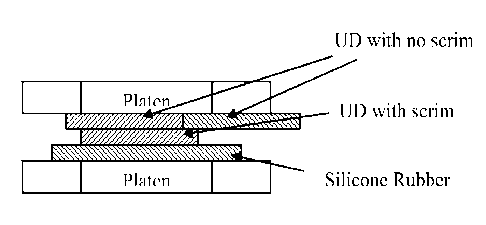
Fig. 1 is a schematic representation of three sheets of material arranged in a
platen
press prior to being pressed.
4
CA 02830926 2013-09-20
WO 2012/170100
PCT/US2012/029937
H0030597 (4820)
DETAILED DESCRIPTION OF THE INVENTION
The invention presents a method for modifying the outer surfaces of fiber
layers
that are impregnated with a non-uniformly distributed polymeric binder
material.
A "fiber layer" as used herein may comprise a single-ply of unidirectionally
oriented fibers, a plurality of non-consolidated plies of unidirectionally
oriented
fibers, a plurality of consolidated plies of unidirectionally oriented fibers,
a woven
fabric, a plurality of consolidated woven fabrics, or any other fabric
structure that
has been formed from a plurality of fibers, including felts, mats and other
structures comprising randomly oriented fibers. A "layer" describes a
generally
planar arrangement. Each fiber layer will have both an outer top surface and
an
outer bottom surface. A "single-ply" of unidirectionally oriented fibers
comprises
an arrangement of non-overlapping fibers that are aligned in a unidirectional,
substantially parallel array. This type of fiber arrangement is also known in
the
art as a "unitape" (unidirectional tape). As used herein, an "array" describes
an
orderly arrangement of fibers or yarns, and a "parallel array" describes an
orderly
parallel arrangement of fibers or yarns. The term "oriented" as used in the
context of "oriented fibers" refers to the alignment of the fibers as opposed
to
stretching of the fibers.
For the purposes of the present invention, a "fiber" is an elongate body the
length
dimension of which is much greater than the transverse dimensions of width and
thickness. The cross-sections of fibers for use in this invention may vary
widely,
and they may be circular, flat or oblong in cross-section. Thus the term
"fiber"
includes filaments, ribbons, strips and the like having regular or irregular
cross-
section, but it is preferred that the fibers have a substantially circular
cross-
section. As used herein, the term "yarn" is defined as a single strand
consisting of
multiple fibers. A single fiber may be formed from just one filament or from
5
CA 02830926 2013-09-20
WO 2012/170100
PCT/US2012/029937
H0030597 (4820)
multiple filaments. A fiber formed from just one filament is referred to
herein as
either a "single-filament" fiber or a "monofilament" fiber, and a fiber formed
from a plurality of filaments is referred to herein as a "multifilament"
fiber.
The term "fabric" describes structures that may include one or more fiber
plies,
with or without molding or consolidation of the plies. For example, a woven
fabric or felt may comprise a single fiber ply. A non-woven fabric formed from
unidirectional fibers typically comprises a plurality of fiber plies stacked
on each
other and consolidated. When used herein, a "single-layer" structure refers to
a
monolithic structure composed of one or more individual plies, wherein
multiple
individual plies have been consolidated into a single unitary structure
together
with a polymeric binder material. By "consolidating" it is meant that the
polymeric binder material together with each fiber ply is combined into a
single
unitary layer. Consolidation can occur via drying, cooling, heating, pressure
or a
combination thereof. Heat and/or pressure may not be necessary, as the fibers
or
fabric layers may just be glued together, as is the case in a wet lamination
process.
The term "composite" refers to combinations of fibers with at least one
polymeric
binder material. A "complex composite" as used herein refers to a consolidated
combination of a plurality of fiber layers. As described herein, "non-woven"
fabrics include all fabric structures that are not formed by weaving. For
example,
non-woven fabrics may comprise a plurality of unitapes that are at least
partially
coated with a polymeric binder material, stacked/overlapped and consolidated
into
a single-layer, monolithic element, as well as a felt or mat comprising non-
parallel, randomly oriented fibers that are (preferably) coated with a
polymeric
binder composition. As used herein, the terms "resin-poor" or "resin-lean" are
used interchangeably with "polymer-poor" or "polymer-lean". The term "resin-
rich" is used interchangeably with "polymer-rich."
6
CA 02830926 2013-09-20
WO 2012/170100
PCT/US2012/029937
H0030597 (4820)
The methods described herein are particularly directed to modifying the outer
surfaces of materials that are considered resin-poor or resin-lean at such
surfaces.
Sub-assemblies having resin-poor surfaces are difficult to tack and require
high
temperatures and pressures to consolidate, and such materials when unmodified
do not process well as armor sub-assemblies useful for the production of armor
articles. A fusible thermoplastic layer applied to the resin-poor surfaces
will
increase the tack of one or both sides of the fabric layer which, improving
its
ability to be merged with other fabric layers and shaped into a sub-assembly,
as
well as allowing lower temperatures and pressures to be used when forming the
sub-assembly. Accordingly, the methods of the invention are particularly
useful
for the production of materials having better processability as armor sub-
assemblies.
The thermoplastic polymer is applied onto a plurality of fibers that are
arranged as
a fiber layer but which may or may not be considered to be a fabric at the
time of
coating. Either one or both outer surfaces of a fiber layer may be treated
depending on need, such as if only one surface is resin-poor. The modified
materials, modified with this additional thermoplastic material on the resin-
poor
surfaces, will process better at moderate conditions. For helmet intermediate
sub-
assemblies, moderate temperatures are those well below the molding temperature
of the final helmet and can be considered as parameters that are easily
attainable
in a relatively short period of time. For example, a sub-assembly of multiple
layers of a first material may be pre-formed into a helmet shape with the
subsequent addition of additional layers of the same material, or of a
different
material. Typically, the sub-assemblies are processed by building up and pre-
forming/consolidating single (2-ply or 4-ply) fiber layers or two fiber layers
at a
time using pressures as low as 30-60 psi (206.8 kPa ¨ 413.7 kPa) and at
temperatures of from about 100 F (37.8 C) to about 220 F (104.4 C), more
7
CA 02830926 2013-09-20
WO 2012/170100
PCT/US2012/029937
H0030597 (4820)
typically from about 130 F (54.4 C) to about 220 F with varying residence
times.
Sub-assemblies are preferably processed at a pressure of from about 30 psi to
about 500 psi (3,447 kPa), more preferably from about 30 psi to about 325 psi
(2,241 kPa), more preferably from about 30 psi to about 150 psi (1,034 kPa)
and
most preferably from about 30 psi to about 60 psi. Typical processing
residence
time at such moderate consolidation conditions is about 30 seconds per added
single or double ply. However, the appropriate pressures and temperatures will
vary by material. For example, matrix materials having a higher melting point
may not process well at these temperatures. Appropriate molding pressures and
temperatures may also vary by article design, and may also affect fiber
wetting/bonding, adhesion between dissimilar materials, density, void
inclusion,
as well as mechanical or crystalline structure of the high performance fibers.
Thereafter, various sub-assemblies are co-processed into a final article at
higher
temperatures and pressures. Final helmet molding temperatures are generally
higher. For example, a typical molding temperature for a final helmet is about
300 F (148.9 C). Helmets produced using woven phenolic aramid based
materials are processed at 320 F (160 C). Polyethylene based unidirectional
materials are processed at about 280 F (137.8 C). Exemplary conditions for
molding a helmet could be molding into a helmet shape at 300 F (148.9 C) and
5,000 psi (34.47 MPa) for 20 minutes. However, the conditions will again vary
by material, etc. It should also be understood that while reference is made
throughout this disclosure to the molding of helmets and helmet sub-assembly
intermediates, the same conditions apply the production of any armor article
or
shape and their respective sub-assembly intermediates as would be conducted by
one skilled in the art.
8
CA 02830926 2013-09-20
WO 2012/170100
PCT/US2012/029937
H0030597 (4820)
Processing of armor sub-assemblies at moderate temperatures is desired because
there is a reduced likelihood of thermal damage to any of the unconstrained
components of the sub-assembly during processing. Moderate pressures can be
achievable with less capable equipment, that which is dedicated to the
production
of sub-assemblies, such as 500 psi for a sub-assembly machine versus 5,000 psi
for a final production press. Another benefit is of pre-forming sub-assemblies
is
the reduction of residence time during consolidation. As the composite fabrics
are usually good thermal insulators, it is time consuming to thoroughly heat
an
entire sub-assembly (rather than component fiber layers of a sub-assembly) to
a
high temperature, especially through surface conduction. Heating the component
fiber layers up to 220 F (104.4 C) is significantly faster than heating a
fully
assembled sub-assembly up to 300 F (148.9 C). Multiple sub-assemblies may
then be consolidated into a complex armor structure, such as a helmet, where
the
supplemental resin is thereby positioned primarily in the interior of the
structure
between adjacent sub-assemblies.
Several different approaches may be effectively employed to increase the
amount
of thermoplastic resin or binder at resin-poor surfaces of non-woven
unidirectional composite fabrics, some in-line during the process step of
laminating multiple fiber plies together to form a fiber layer, or through a
secondary application technique whereby the laminated product undergoes a
subsequent process step. For example, one preferred method is to lay a
separate
thermoplastic web onto the resin-poor side of the fabric and to bond it to the
fabric. This web can be a continuous thermoplastic film, an ordered
discontinuous thermoplastic net, or a non-woven discontinuous fabric or scrim.
Bonding to the fabric may be accomplished by a variety of methods including,
but
not limited to, thermal lamination through a calender nip or a flat-bed
laminator,
or wet lamination as part of the coating process where the resin binder is
applied
9
CA 02830926 2013-09-20
WO 2012/170100
PCT/US2012/029937
H0030597 (4820)
to the fiber. Alternately, a coating of fusible powder of a thermoplastic
resin or
binder may be applied to the resin-poor surface, with subsequent bonding,
melting
and/or fusing of the powder to the surface, such as via a flat-bed laminator.
These
preferred methods are only non-limiting examples of potential techniques and
are
not intended to be a comprehensive listing of all useful methods for
accomplishing the stated goals. After application and/or before bonding of the
thermoplastic layer to a fiber layer, the thermoplastic layer may be tacky at
the
processing temperature employed such that it is capable of adhering adjacent
layers without heating of the thermoplastic layer or fiber layer, and with
minimal
pressure. However, the thermoplastic polymer is typically non-tacky at room
temperature or other typical storage conditions.
The method of the invention may also be utilized to modify surfaces of fiber
layers that are not impregnated with a polymeric binder material, or fiber
layers
that are either fully saturated with a polymeric binder material that has a
high
softening temperature, or having a uniform distribution of polymeric binder
that
has a high softening temperature, it is more specifically intended for
modifying
fiber layers that are impregnated with a polymeric binder material, such as
typical
non-woven fabrics, where the binder is non-uniformly distributed therein and
having one or more resin-poor surfaces. The method of the invention is also
useful for modifying fiber layers that have a uniform distribution of
polymeric
binder but where the surfaces are resin-poor and not suitable for the
fabrication of
sub-assemblies as discussed herein. Depending on the particular processing
conditions of such impregnated fabrics, conditions such as coating technique,
processing aids employed, gravity, surface tension, order of processing, resin
distribution on the fiber layer, resin volume fraction, and resin properties
such as
the resin softening point, all factor into the fabrication of composites
having a
non-uniform distribution of the polymeric binder material characterized by the
CA 02830926 2013-09-20
WO 2012/170100
PCT/US2012/029937
H0030597 (4820)
presence of resin-rich and resin-poor/resin-lean areas. Most typically, these
conditions result in the resin-poor areas being located at the outer surfaces
with
most of the polymeric binder at the interior of the composite. Accordingly,
the
primary need for the thermoplastic polymer is on the outer top surface of the
fiber
layer and/or said outer bottom surface of the fiber layer.
Bonding of the thermoplastic polymer to the fiber layer may generally take
place
at any stage of the process. For example, the thermoplastic polymer may be
bonded to the fiber layer before a consolidation step which consolidates the
plurality of fiber plies and the polymeric binder material into a composite,
in-line
during a consolidation step which consolidates the plurality of fiber plies
and the
polymeric binder material into a composite, or after a consolidation step
which
consolidates the plurality of fiber plies and the polymeric binder material
into a
composite.
The fiber layers and composites formed therefrom preferably comprise ballistic
resistant composites formed from high-strength, high tensile modulus polymeric
fibers. Most preferably, the fibers comprise high strength, high tensile
modulus
fibers which are useful for the formation of ballistic resistant materials and
articles. As used herein, a "high-strength, high tensile modulus fiber" is one
which has a preferred tenacity of at least about 7 g/denier or more, a
preferred
tensile modulus of at least about 150 g/denier or more, and preferably an
energy-
to-break of at least about 8 J/g or more, each both as measured by ASTM D2256.
As used herein, the term "denier" refers to the unit of linear density, equal
to the
mass in grams per 9000 meters of fiber or yarn. As used herein, the term
"tenacity" refers to the tensile stress expressed as force (grams) per unit
linear
density (denier) of an unstressed specimen. The "initial modulus" of a fiber
is the
property of a material representative of its resistance to deformation. The
term
11
CA 02830926 2013-09-20
WO 2012/170100
PCT/US2012/029937
H0030597 (4820)
"tensile modulus" refers to the ratio of the change in tenacity, expressed in
grams-
force per denier (g/d) to the change in strain, expressed as a fraction of the
original fiber length (in/in).
The polymers forming the fibers are preferably high-strength, high tensile
modulus fibers suitable for the manufacture of ballistic resistant
composites/fabrics. Particularly suitable high-strength, high tensile modulus
fiber
materials that are particularly suitable for the formation of ballistic
resistant
composites and articles include polyolefin fibers, including high density and
low
density polyethylene. Particularly preferred are extended chain polyolefin
fibers,
such as highly oriented, high molecular weight polyethylene fibers,
particularly
ultra-high molecular weight polyethylene fibers, and polypropylene fibers,
particularly ultra-high molecular weight polypropylene fibers. Also suitable
are
aramid fibers, particularly para-aramid fibers, polyamide fibers, polyethylene
terephthalate fibers, polyethylene naphthalate fibers, extended chain
polyvinyl
alcohol fibers, extended chain polyacrylonitrile fibers, polybenzazole fibers,
such
as polybenzoxazole (PBO) and polybenzothiazole (PBT) fibers, liquid crystal
copolyester fibers and rigid rod fibers such as M5 fibers. Each of these
fiber
types is conventionally known in the art. Also suitable for producing
polymeric
fibers are copolymers, block polymers and blends of the above materials.
The most preferred fiber types for ballistic resistant fabrics include
polyethylene,
particularly extended chain polyethylene fibers, aramid fibers, polybenzazole
fibers, liquid crystal copolyester fibers, polypropylene fibers, particularly
highly
oriented extended chain polypropylene fibers, polyvinyl alcohol fibers,
polyacrylonitrile fibers and rigid rod fibers, particularly M5 fibers.
Specifically
most preferred fibers are aramid fibers.
12
CA 02830926 2013-09-20
WO 2012/170100
PCT/US2012/029937
H0030597 (4820)
In the case of polyethylene, preferred fibers are extended chain polyethylenes
having molecular weights of at least 500,000, preferably at least one million
and
more preferably between two million and five million. Such extended chain
polyethylene (ECPE) fibers may be grown in solution spinning processes such as
described in U.S. patent 4,137,394 or 4,356,138, which are incorporated herein
by
reference, or may be spun from a solution to form a gel structure, such as
described in U.S. patent 4,551,296 and 5,006,390, which are also incorporated
herein by reference. A particularly preferred fiber type for use in the
invention
are polyethylene fibers sold under the trademark SPECTRA from Honeywell
International Inc. SPECTRA fibers are well known in the art and are
described,
for example, in U.S. patents 4,623,547 and 4,748,064. In addition to
polyethylene, another useful polyolefin fiber type is polypropylene (fibers or
tapes), such as TEGRIS fibers commercially available from Milliken &
Company of Spartanburg, South Carolina.
Also particularly preferred are aramid (aromatic polyamide) or para-aramid
fibers.
Such are commercially available and are described, for example, in U.S. patent
3,671,542. For example, useful poly(p-phenylene terephthalamide) filaments are
produced commercially by DuPont under the trademark of KEVLARO. Also
useful in the practice of this invention are poly(m-phenylene isophthalamide)
fibers produced commercially by DuPont under the trademark NOMEX and
fibers produced commercially by Teijin under the trademark TWARONO; aramid
fibers produced commercially by Kolon Industries, Inc. of Korea under the
trademark HERACRONO; p-aramid fibers SVMTm and RUSARTM which are
produced commercially by Kamensk Volokno JSC of Russia and ARMOSTmp-
aramid fibers produced commercially by JSC Chim Volokno of Russia.
13
CA 02830926 2013-09-20
WO 2012/170100
PCT/US2012/029937
H0030597 (4820)
Suitable polybenzazole fibers for the practice of this invention are
commercially
available and are disclosed for example in U.S. patents 5,286,833, 5,296,185,
5,356,584, 5,534,205 and 6,040,050, each of which is incorporated herein by
reference. Suitable liquid crystal copolyester fibers for the practice of this
invention are commercially available and are disclosed, for example, in U.S.
patents 3,975,487; 4,118,372 and 4,161,470, each of which is incorporated
herein
by reference. Suitable polypropylene fibers include highly oriented extended
chain polypropylene (ECPP) fibers as described in U.S. patent 4,413,110, which
is incorporated herein by reference. Suitable polyvinyl alcohol (PV-OH) fibers
are described, for example, in U.S. patents 4,440,711 and 4,599,267 which are
incorporated herein by reference. Suitable polyacrylonitrile (PAN) fibers are
disclosed, for example, in U.S. patent 4,535,027, which is incorporated herein
by
reference. Each of these fiber types is conventionally known and is widely
commercially available.
M5 fibers are formed from pyridobisimidazole-2,6-diy1 (2,5-dihydroxy-p-
phenylene) and are manufactured by Magellan Systems International of
Richmond, Virginia and are described, for example, in U.S. patents 5,674,969,
5,939,553, 5,945,537, and 6,040,478, each of which is incorporated herein by
reference. Also suitable are combinations of all the above materials, all of
which
are commercially available. For example, the fibrous layers may be formed from
a combination of one or more of aramid fibers, UHMWPE fibers (e.g.
SPECTRA fibers), carbon fibers, etc., as well as fiberglass and other lower-
performing materials.
The fibers may be of any suitable denier, such as, for example, 50 to about
3000
denier, more preferably from about 200 to 3000 denier, still more preferably
from
about 650 to about 2000 denier, and most preferably from about 800 to about
14
CA 02830926 2013-09-20
WO 2012/170100
PCT/US2012/029937
H0030597 (4820)
1500 denier. The selection is governed by considerations of ballistic
effectiveness
and cost. Finer fibers are more costly to manufacture and to weave, but can
produce greater ballistic effectiveness per unit weight.
As stated above, a high-strength, high tensile modulus fiber is one which has
a
preferred tenacity of about 7 g/denier or more, a preferred tensile modulus of
about 150 g/denier or more and a preferred energy-to-break of about 8 J/g or
more, each as measured by ASTM D2256. In the preferred embodiment of the
invention, the tenacity of the fibers should be about 15 g/denier or more,
preferably about 20 g/denier or more, more preferably about 25 g/denier or
more
and most preferably about 30 g/denier or more. Preferred fibers also have a
preferred tensile modulus of about 300 g/denier or more, more preferably about
400 g/denier or more, more preferably about 500 g/denier or more, more
preferably about 1,000 g/denier or more and most preferably about 1,500
g/denier
or more. Preferred fibers also have a preferred energy-to-break of about 15
J/g or
more, more preferably about 25 J/g or more, more preferably about 30 J/g or
more
and most preferably have an energy-to-break of about 40 J/g or more. These
combined high strength properties are obtainable by employing well known
processes. U.S. patents 4,413,110, 4,440,711, 4,535,027, 4,457,985, 4,623,547
4,650,710 and 4,748,064 generally discuss the formation of preferred high
strength, extended chain polyethylene fibers. Such methods, including solution
grown or gel fiber processes, are well known in the art. Methods of forming
each
of the other preferred fiber types, including para-aramid fibers, are also
conventionally known in the art, and the fibers are commercially available.
The polymeric binder impregnating the fiber layers either partially or
substantially
coats the individual fibers of the fiber layers. In a typical process, the
polymeric
binder becomes non-uniformly distributed in a fiber layer largely due to the
CA 02830926 2013-09-20
WO 2012/170100
PCT/US2012/029937
H0030597 (4820)
effects of gravity and surface tension, among other factors previously
mentioned.
For example, in one process of forming non-woven fiber layers from a plurality
of
unidirectional fiber plies (unitapes), the polymeric binder is applied to a
first ply
and then, while the coated fiber ply is still wet, it is contacted with a
disposable
silicone-coated release paper. The wet resin typically will not distribute
itself
uniformly throughout the thickness of the unidirectional fiber web because
gravity
and the difference in surface tension between the silicone-coated paper on one
side and the air on the other side causes a concentration gradient through the
thickness, with the filaments adjacent to the release paper being heavily
saturated
with resin and the filaments exposed to the air being resin-lean. Next, a
second
wet, coated fiber web is contacted at an angle (typically 90 ) with the resin-
lean
side of the first, now dried, fiber ply. The wet resin will again distribute
itself
non-uniformly, with a higher concentration of resin at the interface of the
two
orthogonal (0 /90 ) fiber plies and the air-side or top-side (outer top
surface)
being resin-lean due to these conditions. While this process is exemplified
for an
embodiment where the polymeric binder is non-uniformly distributed in the
fiber
layers, it is not intended to be mandatory or limiting. The polymeric binder
material may be non-uniformly distributed within the fiber layer either prior
to,
during or after the application of the thermoplastic polymer to the fiber
layer, as
well as prior to, during or after bonding of the thermoplastic polymer to the
fiber
layer.
The polymeric binder material is also commonly known in the art as a
"polymeric
matrix" material, and these terms are used interchangeably herein. These terms
are conventionally known in the art and describe a material that binds fibers
together either by way of its inherent adhesive characteristics or after being
subjected to well known heat and/or pressure conditions. Such a "polymeric
matrix" or "polymeric binder" material may also provide a fabric with other
16
CA 02830926 2013-09-20
WO 2012/170100
PCT/US2012/029937
H0030597 (4820)
desirable properties, such as abrasion resistance and resistance to
deleterious
environmental conditions, so it may be desirable to coat the fibers with such
a
binder material even when its binding properties are not important, such as
with
woven fabrics. It is generally not possible to form sub-assemblies from woven
fabrics unless they are impregnated or coated with some form of polymeric
binder
material. Accordingly, for the purposes of this invention, the methods of the
invention are directed to woven fabrics that either are not impregnated with a
binder, or when impregnated, have resin-poor areas or surfaces similar to non-
woven fabrics described herein that impede the consolidation of multiple sub-
assemblies. To merge multiple woven fabrics, the fibers comprising the woven
fabrics are at least partially coated with a polymeric binder, followed by a
consolidation step similar to that conducted with non-woven fiber layers. Such
a
consolidation step may be conducted to merge multiple woven fiber layers with
each other, or to further impregnate the woven fabric with the binder
material.
Suitable polymeric binder materials include both low modulus, elastomeric
materials and high modulus, rigid materials. As used herein throughout, the
term
tensile modulus means the modulus of elasticity as measured by ASTM 2256 for
a fiber and by ASTM D638 for a polymeric binder material. A low or high
modulus binder may comprise a variety of polymeric and non-polymeric
materials. A preferred polymeric binder comprises a low modulus elastomeric
material. For the purposes of this invention, a low modulus elastomeric
material
has a tensile modulus measured at about 6,000 psi (41.4 MPa) or less according
to
ASTM D638 testing procedures. A low modulus polymer preferably has, the
tensile modulus of the elastomer is about 4,000 psi (27.6 MPa) or less, more
preferably about 2400 psi (16.5 MPa) or less, more preferably 1200 psi (8.23
MPa) or less, and most preferably is about 500 psi (3.45 MPa) or less. The
glass
transition temperature (Tg) of the elastomer is preferably less than about 0
C,
17
CA 02830926 2013-09-20
WO 2012/170100
PCT/US2012/029937
H0030597 (4820)
more preferably the less than about -40 C, and most preferably less than about
-
50 C. The elastomer also has a preferred elongation to break of at least about
50%, more preferably at least about 100% and most preferably has an elongation
to break of at least about 300%.
A wide variety of materials and formulations having a low modulus may be
utilized as the polymeric binder. Representative examples include
polybutadiene,
polyisoprene, natural rubber, ethylene-propylene copolymers, ethylene-
propylene-
diene terpolymers, polysulfide polymers, polyurethane elastomers,
chlorosulfonated polyethylene, polychloroprene, plasticized polyvinylchloride,
butadiene acrylonitrile elastomers, poly(isobutylene-co-isoprene),
polyacrylates,
polyesters, polyethers, fluoroelastomers, silicone elastomers, copolymers of
ethylene, polyamides (useful with some fiber types), acrylonitrile butadiene
styrene, polycarbonates, and combinations thereof, as well as other low
modulus
polymers and copolymers curable below the melting point of the fiber. Also
preferred are blends of different elastomeric materials, or blends of
elastomeric
materials with one or more thermoplastics.
Particularly useful are block copolymers of conjugated dienes and vinyl
aromatic
monomers. Butadiene and isoprene are preferred conjugated diene elastomers.
Styrene, vinyl toluene and t-butyl styrene are preferred conjugated aromatic
monomers. Block copolymers incorporating polyisoprene may be hydrogenated
to produce thermoplastic elastomers having saturated hydrocarbon elastomer
segments. The polymers may be simple tri-block copolymers of the type A-B-A,
multi-block copolymers of the type (AB)õ (n= 2-10) or radial configuration
copolymers of the type R-(BA)x (x=3-150); wherein A is a block from a
polyvinyl
aromatic monomer and B is a block from a conjugated diene elastomer. Many of
these polymers are produced commercially by Kraton Polymers of Houston, TX
18
CA 02830926 2013-09-20
WO 2012/170100
PCT/US2012/029937
H0030597 (4820)
and described in the bulletin "Kraton Thermoplastic Rubber", SC-68-81. Also
useful are resin dispersions of styrene-isoprene-styrene (SIS) block copolymer
sold under the trademark PRINLIN and commercially available from Henkel
Technologies, based in Dusseldorf, Germany. The most preferred low modulus
polymeric binder polymer comprises styrenic block copolymers sold under the
trademark KRATON commercially produced by Kraton Polymers. The most
preferred polymeric binder material comprises a polystyrene-polyisoprene-
polystrene-block copolymer sold under the trademark KRATON .
While low modulus polymeric matrix binder materials are most useful for the
formation of flexible armor, such as ballistic resistant vests, high modulus,
rigid
materials useful for forming hard armor articles, such as helmets, are
particularly
preferred herein. Preferred high modulus, rigid materials generally have a
higher
initial tensile modulus than 6,000 psi. Preferred high modulus, rigid
polymeric
binder materials useful herein include polyurethanes (both ether and ester
based),
epoxies, polyacrylates, phenolic/polyvinyl butyral (PVB) polymers, vinyl ester
polymers, styrene-butadiene block copolymers, as well as mixtures of polymers
such as vinyl ester and diallyl phthalate or phenol formaldehyde and polyvinyl
butyral. A particularly preferred rigid polymeric binder material for use in
this
invention is a thermosetting polymer, preferably soluble in carbon-carbon
saturated solvents such as methyl ethyl ketone, and possessing a high tensile
modulus when cured of at least about 1x10⁶ psi (6895 MPa) as measured by
ASTM D638. Particularly preferred rigid polymeric binder materials are those
described in U.S. patent 6,642,159, the disclosure of which is incorporated
herein
by reference. The polymeric binder, whether a low modulus material or a high
modulus material, may also include fillers such as carbon black or silica, may
be
extended with oils, or may be vulcanized by sulfur, peroxide, metal oxide or
radiation cure systems as is well known in the art. Most specifically
preferred are
19
CA 02830926 2013-09-20
WO 2012/170100
PCT/US2012/029937
H0030597 (4820)
polyurethane polymeric matrix binders within the range of both soft and rigid
materials at a modulus ranging from about 2,000 psi (13.79 MPa) to about 8,000
psi (55.16 MPa).
The rigidity, impact and ballistic properties of the articles formed from the
composites of the invention are affected by the tensile modulus of the
polymeric
binder polymer coating the fibers. For example, U.S. patent 4,623,574
discloses
that fiber reinforced composites constructed with elastomeric matrices having
tensile moduli less than about 6,000 psi (41,300 kPa) have superior ballistic
properties compared both to composites constructed with higher modulus
polymers, and also compared to the same fiber structure without a polymeric
binder material. However, low tensile modulus polymeric binder material
polymers also yield lower rigidity composites. Further, in certain
applications,
particularly those where a composite must function in both anti-ballistic and
structural modes, there is needed a superior combination of ballistic
resistance and
rigidity. Accordingly, the most appropriate type of polymeric binder polymer
to
be used will vary depending on the type of article to be formed from the
composites of the invention. In order to achieve a compromise in both
properties,
a suitable polymeric binder may combine both low modulus and high modulus
materials to form a single polymeric binder.
The polymeric binder material may be applied either simultaneously or
sequentially to a plurality of fibers arranged as a fiber web (e.g. a parallel
array or
a felt) to form a coated web, applied to a woven fabric to form a coated woven
fabric, or as another arrangement, to thereby impregnate the fiber layers with
the
binder. As used herein, the term "impregnated with" is synonymous with
"embedded in" as well as "coated with" or otherwise applied with the coating
where the binder material diffuses into the fiber layer and is not simply on a
CA 02830926 2013-09-20
WO 2012/170100
PCT/US2012/029937
H0030597 (4820)
surface of the fiber layers. The polymeric material may also be applied onto
at
least one array of fibers that is not part of a fiber web, followed by weaving
the
fibers into a woven fabric or followed by formulating a non-woven fabric
following the methods described previously herein. Techniques of forming
woven and non-woven fiber plies, layers and fabrics are well known in the art.
Although not required, fibers forming woven fiber layers are at least
partially
coated with a polymeric binder, followed by a consolidation step similar to
that
conducted with non-woven fiber layers. Such a consolidation step may be
conducted to merge multiple woven fiber layers with each other, or to further
merge the binder with the fibers of said woven fabric. For example, a
plurality of
woven fiber layers do not necessarily have to be consolidated, and may be
attached by other means, such as with a conventional adhesive, or by
stitching.
Generally, a polymeric binder coating is necessary to efficiently merge, i.e.
consolidate, a plurality of non-woven fiber plies. The polymeric binder
material
may be applied onto the entire surface area of the individual fibers or only
onto a
partial surface area of the fibers. Most preferably, the coating of the
polymeric
binder material is applied onto substantially all the surface area of each
individual
fiber forming a fiber layer of the invention. Where a fiber layer comprises a
plurality of yarns, each fiber forming a single strand of yarn is preferably
coated
with the polymeric binder material.
Any appropriate application method may be utilized to apply the polymeric
binder
material and the term "coated" is not intended to limit the method by which
the
polymer layers are applied onto the filaments/fibers. The polymeric binder
material is applied directly onto the fiber surfaces using any appropriate
method
that would be readily determined by one skilled in the art, and the binder
then
21
CA 02830926 2013-09-20
WO 2012/170100
PCT/US2012/029937
H0030597 (4820)
typically diffuses into the fiber layer as discussed herein. For example, the
polymeric binder materials may be applied in solution, emulsion or dispersion
form by spraying, extruding or roll coating a solution of the polymer material
onto
fiber surfaces, wherein a portion of the solution comprises the desired
polymer or
polymers and a portion of the solution comprises a solvent capable of
dissolving
or dispersing the polymer or polymers, followed by drying. Alternately, the
polymeric binder material may be extruded onto the fibers using conventionally
known techniques, such as through a slot-die, or through other techniques such
as
direct gravure, Meyer rod and air knife systems, which are well known in the
art.
Another method is to apply a neat polymer of the binder material onto fibers
either as a liquid, a sticky solid or particles in suspension or as a
fluidized bed.
Alternatively, the coating may be applied as a solution, emulsion or
dispersion in
a suitable solvent which does not adversely affect the properties of fibers at
the
temperature of application. For example, the fibers can be transported through
a
solution of the polymeric binder material to substantially coat the fibers and
then
dried.
In another coating technique, the fibers may be dipped into a bath of a
solution
containing the polymeric binder material dissolved or dispersed in a suitable
solvent, and then dried through evaporation or volatilization of the solvent.
This
method preferably at least partially coats each individual fiber with the
polymeric
material, preferably substantially coating or encapsulating each of the
individual
fibers and covering all or substantially all of the filament/fiber surface
area with
the polymeric binder material. The dipping procedure may be repeated several
times as required to place a desired amount of polymer material onto the
fibers.
Other techniques for applying a coating to the fibers may be used, including
coating of a gel fiber precursor when appropriate, such as by passing the gel
fiber
22
CA 02830926 2013-09-20
WO 2012/170100
PCT/US2012/029937
H0030597 (4820)
through a solution of the appropriate coating polymer under conditions to
attain
the desired coating. Alternatively, the fibers may be extruded into a
fluidized bed
of an appropriate polymeric powder.
The fibers may be coated with the polymeric binder either before or after the
fibers are arranged into one or more plies/layers, or before or after the
fibers are
woven into a woven fabric. Woven fabrics may be formed using techniques that
are well known in the art using any fabric weave, such as plain weave,
crowfoot
weave, basket weave, satin weave, twill weave and the like. Plain weave is
most
common, where fibers are woven together in an orthogonal 0 /90 orientation.
Either prior to or after weaving, the individual fibers of each woven fabric
material may or may not be coated with the polymeric binder material.
Typically,
weaving of fabrics is performed prior to coating fibers with the polymeric
binder,
where the woven fabrics are thereby impregnated with the binder. However, the
invention is not intended to be limited by the stage at which the polymeric
binder
is applied to the fibers, nor by the means used to apply the polymeric binder.
Methods for the production of non-woven fabrics are well known in the art. In
the preferred embodiments herein, a plurality of fibers are arranged into at
least
one array, typically being arranged as a fiber web comprising a plurality of
fibers
aligned in a substantially parallel, unidirectional array. In a typical
process for
forming non-woven unidirectionally aligned fiber plies, fiber bundles are
supplied
from a creel and led through guides and one or more spreader bars into a
collimating comb, followed by coating the fibers with a polymeric binder
material. A typical fiber bundle will have from about 30 to about 2000
individual
fibers. The spreader bars and collimating comb disperse and spread out the
bundled fibers, reorganizing them side-by-side in a coplanar fashion. Ideal
fiber
spreading results in the individual filaments or individual fibers being
positioned
23
CA 02830926 2013-09-20
WO 2012/170100
PCT/US2012/029937
H0030597 (4820)
next to one another in a single fiber plane, forming a substantially
unidirectional,
parallel array of fibers without fibers overlapping each other. At this point,
scouring the fibers before or during this spreading step may enhance and
accelerate the spreading of the fibers into such a parallel array. Fiber
scouring is a
process in which fibers (or fabric) are passed through a chemical solution
which
removes any of the undesirable residual fiber finish (or weaving aid) that may
have been applied to the fibers during or after fabrication. Fiber scouring
may
also improve the bond strength of a subsequently applied polymeric binder
material (or a subsequently applied protective film) on the fibers, and
accordingly,
less binder may be needed. By reducing amount of binder, a greater number of
fibers may be included in a fabric, producing a lighter ballistic material
with
improved strength. This also leads to increased projectile engagement with the
fibers, improved stab resistance of resulting fabric composites and an
increased
resistance of the composites against repeated impacts. Following fiber
spreading
and collimating, the fibers of such a parallel array typically contain from
about 3
to 12 fiber ends per inch (1.2 to 4.7 ends per cm), depending on the
filament/fiber
thickness.
After the fibers are coated with the binder material, the coated fibers are
formed
into non-woven fiber layers that comprise a plurality of overlapping, non-
woven
fiber plies that are consolidated into a single-layer, monolithic element. In
a
preferred non-woven fabric structure of the invention, a plurality of stacked,
overlapping unitapes are formed wherein the parallel fibers of each single ply
(unitape) are positioned orthogonally to the parallel fibers of each adjacent
single
ply relative to the longitudinal fiber direction of each single ply. The stack
of
overlapping non-woven fiber plies is consolidated under heat and pressure, or
by
adhering the coatings of individual fiber plies, to form a single-layer,
monolithic
element which has also been referred to in the art as a single-layer,
consolidated
24
CA 02830926 2013-09-20
WO 2012/170100
PCT/US2012/029937
H0030597 (4820)
network where a "consolidated network" describes a consolidated (merged)
combination of fiber plies with the polymeric matrix/binder. Articles of the
invention may also comprise hybrid consolidated combinations of woven fabrics
and non-woven fabrics, as well as combinations of non-woven fabrics formed
from unidirectional fiber plies and non-woven felt fabrics.
Most typically, non-woven fiber layers or fabrics include from 1 to about 6
plies,
but may include as many as about 10 to about 20 plies as may be desired for
various applications. The greater the number of plies translates into greater
ballistic resistance, but also greater weight. Accordingly, the number of
fiber
plies forming a fiber layer composite and/or fabric composite or an article of
the
invention varies depending upon the ultimate use of the fabric or article. For
example, in body armor vests for military applications, in order to form an
article
composite that achieves a desired 1.0 pound per square foot or less areal
density
(4.9 kg/m2), a total of about 100 plies (or layers) to about 50 individual
plies (or
layers) may be required, wherein the plies/layers may be woven, knitted,
felted or
non-woven fabrics (with parallel oriented fibers or other arrangements) formed
from the high-strength fibers described herein. In another embodiment, body
armor vests for law enforcement use may have a number of plies/layers based on
the National Institute of Justice (NIJ) Threat Level. For example, for an NIJ
Threat Level MA vest, there may be a total of 40 plies. For a lower NIJ Threat
Level, fewer plies/layers may be employed. The invention allows for the
incorporation of a greater number of fiber plies to achieve the desired level
of
ballistic protection without increasing the fabric weight as compared to other
known ballistic resistant structures.
As is conventionally known in the art, excellent ballistic resistance is
achieved
when individual fiber plies are cross-plied such that the fiber alignment
direction
CA 02830926 2013-09-20
WO 2012/170100
PCT/US2012/029937
H0030597 (4820)
of one ply is rotated at an angle with respect to the fiber alignment
direction of
another ply. Most preferably, the fiber plies are cross-plied orthogonally at
0 and
90 angles, but adjacent plies can be aligned at virtually any angle between
about
0 and about 900 with respect to the longitudinal fiber direction of another
ply.
Methods of consolidating fiber plies to form fiber layers and composites are
well
known, such as by the methods described in U.S. patent 6,642,159.
Consolidation
can occur via drying, cooling, heating, pressure or a combination thereof.
Heat
and/or pressure may not be necessary, as the fibers or fabric layers may just
be
consolidation is done by positioning the individual fiber plies on one another
under conditions of sufficient heat and pressure to cause the plies to combine
into
a unitary fabric. Consolidation may be done at temperatures ranging from about
50 C to about 175 C, preferably from about 105 C to about 175 C, and at
26
CA 02830926 2013-09-20
WO 2012/170100
PCT/US2012/029937
H0030597 (4820)
"glued" together with the binder polymer and run through a flat bed laminator
to
improve the uniformity and strength of the bond. Further, the consolidation
and
polymer application/bonding steps may comprise two separate steps or a single
consolidation/lamination step.
Alternately, consolidation may be achieved by molding under heat and pressure
in
a suitable molding apparatus. Generally, molding is conducted at a pressure of
from about 50 psi (344.7 kPa) to about 5,000 psi (34,470 kPa), more preferably
about 100 psi (689.5 kPa) to about 3,000 psi (20,680 kPa), most preferably
from
about 150 psi (1,034 kPa) to about 1,500 psi (10,340 kPa). Molding may
alternately be conducted at higher pressures of from about 5,000 psi (34,470
kPa)
to about 15,000 psi (103,410 kPa), more preferably from about 750 psi (5,171
kPa) to about 5,000 psi, and more preferably from about 1,000 psi to about
5,000
psi. The molding step may take from about 4 seconds to about 45 minutes.
Preferred molding temperatures range from about 200 F (-93 C) to about 350 F
(-177 C), more preferably at a temperature from about 200 F to about 300 F and
most preferably at a temperature from about 200 F to about 280 F. The pressure
under which the fiber layers and fabric composites of the invention are molded
has a direct effect on the stiffness or flexibility of the resulting molded
product.
Particularly, the higher the pressure at which they are molded, the higher the
stiffness, and vice-versa. In addition to the molding pressure, the quantity,
thickness and composition of the fiber plies and polymeric binder coating type
also directly affects the stiffness of the articles formed from the
composites.
While each of the molding and consolidation techniques described herein are
similar, each process is different. Particularly, molding is a batch process
and
consolidation is a generally continuous process. Further, molding typically
involves the use of a mold, such as a shaped mold or a match-die mold when
27
CA 02830926 2013-09-20
WO 2012/170100
PCT/US2012/029937
H0030597 (4820)
forming a flat panel, and does not necessarily result in a planar product.
Normally
consolidation is done in a flat-bed laminator, a calendar nip set or as a wet
lamination to produce soft (flexible) body armor fabrics. Molding is typically
reserved for the manufacture of hard armor, e.g. rigid plates. In either
process,
suitable temperatures, pressures and times are generally dependent on the type
of
polymeric binder coating materials, polymeric binder content, process used and
fiber type.
To produce a fabric article having sufficient ballistic resistance properties,
the
total weight of the binder/matrix coating preferably comprises from about 2%
to
about 50% by weight, more preferably from about 5% to about 30%, more
preferably from about 7% to about 20%, and most preferably from about 11% to
about 16% by weight of the fibers plus the weight of the coating, wherein 16%
is
most preferred for non-woven fabrics. A lower binder/matrix content is
appropriate for woven fabrics, wherein a polymeric binder content of greater
than
zero but less than 10% by weight of the fibers plus the weight of the coating
is
typically most preferred. This is not intended as limiting. For example,
phenolic/PVB impregnated woven aramid fabrics are sometimes fabricated with a
higher resin content of from about 20% to about 30%, although around 12%
content is typically preferred.
Either prior to, during or after consolidation of non-woven fiber layers, or
after
weaving of woven fiber layers, the thermoplastic polymer is applied onto the
outer top surface of the fiber layer and/or the outer bottom surface of the
fiber
layer when the respective surfaces are resin-lean. This will increase the
amount
of thermoplastic resin or binder at the resin-poor surface of the fiber layer.
Several different approaches could be employed, some in-line during the
current
process step which laminates multiple cross-plies of product together, or
through
28
CA 02830926 2013-09-20
WO 2012/170100
PCT/US2012/029937
H0030597 (4820)
a secondary application technique whereby the laminated product undergoes a
subsequent process step. One method is to lay a second thermoplastic web onto
the resin-poor side of the fabric and to bond it to the fabric. This web can
be a
continuous thermoplastic film, an ordered discontinuous thermoplastic net, or
a
non-woven discontinuous fabric or scrim. The bonding can be accomplished by a
variety of methods including, but not limited to, thermal lamination through a
calender nip or a flat-bed laminator, and wet lamination as part of the
coating
process where the resin binder is applied to the fiber. Another useful method
is to
apply a powder coating of a thermoplastic resin or binder to the resin-poor
surface, with the subsequent bonding or fusing of the powder to the surface
with a
flat-bed laminator. These methods are non-limiting representative examples of
potential techniques and not a comprehensive listing of all useful methods.
Most
preferably the thermoplastic polymer is a heat-activated, non-woven, adhesive
web, such as SPUNFAB , commercially available from Keuchel Associates, Inc.
of Cuyahoga Falls, Ohio; THERMOPLASTTm and HELIOPLASTTm webs, nets
and films, commercially available from Protechnic S.A. of Cernay, France; as
well as others. It should be further understood that the fiber ply/fiber layer
consolidation and polymer application/bonding steps may comprise either two
separate steps or a single consolidation/lamination step.
Suitable polymers for the thermoplastic polymer layer non-exclusively include
thermoplastic polymers non-exclusively may be selected from the group
consisting of polyolefins, polyamides, polyesters (particularly polyethylene
terephthalate (PET) and PET copolymers), polyurethanes, vinyl polymers,
ethylene vinyl alcohol copolymers, ethylene octane copolymers, acrylonitrile
copolymers, acrylic polymers, vinyl polymers, polycarbonates, polystyrenes,
fluoropolymers and the like, as well as co-polymers and mixtures thereof,
including ethylene vinyl acetate (EVA) and ethylene acrylic acid. Also useful
are
29
CA 02830926 2013-09-20
WO 2012/170100
PCT/US2012/029937
H0030597 (4820)
natural and synthetic rubber polymers. Of these, polyolefin and polyamide
layers
are preferred. The preferred polyolefin is a polyethylene. Non-limiting
examples
of useful polyethylenes are low density polyethylene (LDPE), linear low
density
polyethylene (LLDPE), Medium Density Polyethylene (MDPE), linear medium
density polyethylene (LMDPE), linear very-low density polyethylene (VLDPE),
linear ultra-low density polyethylene (ULDPE), high density polyethylene
(HDPE) and co-polymers and mixtures thereof. Of these, the most preferred
polyethylene is MDPE. Of all the above, most preferred is a polyamide web,
particularly SPUNFAB polyamide webs. SPUNFAB polyamide webs have a
melting point of typically from about 75 C to about 200 C, but this is not
limiting.
As stated above, the thermoplastic polymer is preferably bonded to the fiber
layer
using well known techniques, such as thermal lamination. Typically, laminating
is done by positioning the individual layers on one another under conditions
of
sufficient heat and pressure to cause the layers to combine into a unitary
film.
The individual layers are positioned on one another, and the combination is
then
typically passed through the nip of a pair of heated laminating rollers by
techniques well known in the art. Lamination heating may be done at
temperatures ranging from about 95 C to about 175 C, preferably from about
105 C to about 175 C, at pressures ranging from about 5 psig (0.034 MPa) to
about 100 psig (0.69 MPa), for from about 5 seconds to about 36 hours,
preferably from about 30 seconds to about 24 hours.
Coatings of the thermoplastic polymer on the fiber layer surfaces are
preferably
very thin, having preferred layer thicknesses of from about 1 iim to about 250
iim,
more preferably from about 5 iim to about 25 iim and most preferably from
about
5 p.m to about 9 p.m. It should be understood, however, that these thicknesses
are
CA 02830926 2013-09-20
WO 2012/170100
PCT/US2012/029937
H0030597 (4820)
not necessarily descriptive of non-continuous webs. For example, SPUNFAB
net-like materials are several mils thick where material is present, but most
of the
web is just air. These materials are better described by their basis weight,
e.g.
particularly preferred is a SPUNFAB web having a basis weight of 6 grams per
square meter (gsm). The thickness of the individual fiber layers will
correspond
to the thickness of the individual fibers. While such thicknesses are
preferred, it
is to be understood that other film thicknesses may be produced to satisfy a
particular need and yet fall within the scope of the present invention. The
thermoplastic polymer preferably comprises from about 1% to about 25% by
weight of the overall composite, more preferably from about 1% to about 17%
percent by weight of the overall composite and most preferably from 1% to 12%.
The percent by weight of the polymer film layers will generally vary depending
on the number of fiber layers included. For example, a 6 gsm SPUNFAB layer
consists of just over 1 wt.% of a 500 gsm final product.
The thickness of the individual fabrics/composites/fiber layers will
correspond to
the thickness of the individual fibers and the number of fiber layers
incorporated
into a fabric. A preferred woven fabric will have a preferred thickness of
from
about 25 iim to about 600 iim per layer, more preferably from about 50 iim to
about 385 iim and most preferably from about 75 iim to about 255 iim per
layer.
A preferred non-woven fabric, i.e. a non-woven, single-layer, consolidated
network, will have a preferred thickness of from about 12 iim to about 600
iim,
more preferably from about 50 iim to about 385 iim and most preferably from
about 75 p.m to about 255 iim, wherein a single-layer, consolidated network
typically includes two consolidated plies (i.e. two unitapes). While such
thicknesses are preferred, it is to be understood that other thicknesses may
be
produced to satisfy a particular need and yet fall within the scope of the
present
invention.
31
CA 02830926 2013-09-20
WO 2012/170100
PCT/US2012/029937
H0030597 (4820)
The fabrics/composites of the invention will have a preferred areal density of
from about 20 grams/m2 (0.004 lb/ft2 (psf)) to about 1000 gsm (0.2 psf). More
preferable areal densities for the fabrics/composites of this invention will
range
from about 30 gsm (0.006 psf) to about 500 gsm (0.1 psf). The most preferred
areal density for fabrics/composites of this invention will range from about
50
gsm (0.01 psf) to about 250 gsm (0.05 psf). Articles of the invention
comprising
multiple fiber layers stacked one upon another and consolidated will further
have
a preferred areal density of from about 1000 gsm (0.2 psf) to about 40,000 gsm
(8.0 psf), more preferably from about 2000 gsm (0.40 psf) to about 30,000 gsm
(6.0 psf), more preferably from about 3000 gsm (0.60 psf) to about 20,000 gsm
(4.0 psf), and most preferably from about 3750 gsm (0.75 psf) to about 15,000
gsm (3.0 psf). A typical range for composite articles shaped into helmets is
from
about 7,500 gsm (1.50 psf) to about 12,500 gsm (2.50 psf).
The fabrics of the invention may be used in various applications to form a
variety
of different ballistic resistant articles using well known techniques,
including
flexible, soft armor articles as well as rigid, hard armor articles. For
example,
suitable techniques for forming ballistic resistant articles are described in,
for
example, U.S. patents 4,623,574, 4,650,710, 4,748,064, 5,552,208, 5,587,230,
6,642,159, 6,841,492 and 6,846,758, all of which are incorporated herein by
reference to the extent not incompatible herewith. The composites are
particularly useful for the formation of hard armor and shaped or unshaped sub-
assembly intermediates formed in the process of fabricating hard armor
articles.
By "hard" armor is meant an article, such as helmets, panels for military
vehicles,
or protective shields, which have sufficient mechanical strength so that it
maintains structural rigidity when subjected to a significant amount of stress
and
is capable of being freestanding without collapsing. Such hard articles are
32
CA 02830926 2013-09-20
WO 2012/170100
PCT/US2012/029937
H0030597 (4820)
preferably, but not exclusively, formed using a high tensile modulus binder
material.
The structures can be cut into a plurality of discrete sheets and stacked for
formation into an article or they can be formed into a precursor which is
subsequently used to form an article. Such techniques are well known in the
art.
In a most preferred embodiment of the invention, a plurality of fiber layers
are
provided, each comprising a consolidated plurality of fiber plies, wherein a
thermoplastic polymer is bonded to at least one outer surface of each fiber
layer
either before, during or after a consolidation step which consolidates the
plurality
of fiber plies, wherein the plurality of fiber layers are subsequently merged
by
another consolidation step which consolidates the plurality of fiber layers
into an
armor article or sub-assembly of an armor article.
The following examples serve to illustrate the invention:
EXAMPLE 1
An aramid fiber-based, non-woven, unidirectional composite material (1000-
denier aramid fiber; fiber areal density: 45 gsm per ply; 4-ply laminate
(0 /90 /0 /90 ) material; polyurethane-based matrix resin; resin content: ¨16
wt.%) containing various scrim materials bonded to its resin-poor surface was
compared to a control material of identical construction but without a scrim
material. Three 12" x 12" sheets of the unidirectional composite material were
formed into a sub-assembly in a press using various processing conditions.
Fig. 1
illustrates how the three sheets of material were arranged in the platen
press, prior
to subjecting them to the process conditions. The total area of pressure
exerted on
the material was 12" x 12". The two upper sheets of composite material were
offset, which created two zones ¨ a 1" x 12" overlapped region and a 11" x 12"
33
CA 02830926 2013-09-20
WO 2012/170100 PCT/US2012/029937
H0030597 (4820)
overlapped region, where the first upper sheet and bottom sheet contact
surface
area was 11" x 12", and second upper sheet and bottom sheet contact surface
area
was 1" x 12". Only the lower sheet for the material trials with scrim had the
scrim
treatment applied. To assess whether or not the surface treatment was
successful,
the materials were evaluated by determining whether or not the materials
"tacked"
together in the 1" x 12" area of overlap, or in the 11" x 12" area of overlap
as
illustrated in Fig. 1 when placed into a heated platen press situated with a
silicone
rubber sheet on the lower platen to simulate a pre-forming process at various
temperatures, pressures and residence times.
The processing conditions included varying the pressure, temperature and time
of
the pre-forming step, followed by assessing whether or not the combination of
pre-forming conditions resulted in successful tack of the material to itself.
Results
are shown in Table 1:
TABLE 1
Pressure
Product Temp ( F) Time (sec) Tack 11" x 12" Tack 1" x 12"
(psi)
Control with 125
150 30 No (Failed) No (Failed)
No Scrim (51.7 C)
Control with 175
150 30 Yes (Passed) Yes
(Passed)
No Scrim (79.4 C)
Control with 125
150 150 No (Failed) No (Failed)
No Scrim (51.7 C)
Control with 175
150 150 Yes (Passed) Yes
(Passed)
No Scrim (79.4 C)
34
CA 02830926 2013-09-20
WO 2012/170100 PCT/US2012/029937
H0030597 (4820)
Control with 150
325 90 Yes (Passed) No
(Failed)
No Scrim (65.6 C)
Control with 150
325 90 Yes (Passed) No
(Failed)
No Scrim (65.6 C)
Control with 150
325 90 No (Failed) No
(Failed)
No Scrim (65.6 C)
Control with 125
500 30 No (Failed) No
(Failed)
No Scrim (51.7 C)
Control with 125
500 150 No (Failed) No
(Failed)
No Scrim (51.7 C)
Control with 175
500 30 Yes (Passed) Yes
(Passed)
No Scrim (79.4 C)
Control with 175
500 150 Yes (Passed) Yes
(Passed)
No Scrim (79.4 C)
Control + 150
325 30 Yes (Passed) No
(Failed)
Scrim 1 (65.6 C)
Control + 150
325 90 Yes (Passed) Yes
(Passed)
Scrim 1 (65.6 C)
Control + 150
325 30 No (Failed) No
(Failed)
Scrim 2 (65.6 C)
Control + 150
325 90 No (Failed) No
(Failed)
Scrim 2 (65.6 C)
Control + 150
325 30 Yes (Passed) Yes
(Passed)
Scrim 3 (65.6 C)
Control + 150
325 90 Yes (Passed) Yes
(Passed)
Scrim 3 (65.6 C)
CA 02830926 2013-09-20
WO 2012/170100
PCT/US2012/029937
H0030597 (4820)
*Scrim 1 = SPUNFAB 100HWE 6-gsm fusible co-polyamide resin web;
Melting Range, DSC (ASTM D3418) of 100 C to 115 C.
**Scrim 2 = SPUNFAB 408HWG 6-gsm fusible polyolefin resin web; Stick
Point (Kofler Hot Bench) (QWI-1005) of 88 C to 98 C.
***Scrim 3 = SPUNFAB 308HWF 6-gsm fusible EVA resin web; Melting
Range, DSC (ASTM D3418) of 120 C to 135 C.
The above data demonstrates that the use of scrim materials beneficially
allows
the use lower temperatures, preferably at or below 175 F (79.4 C), and low
pressures to process the sub-assembly.
EXAMPLE 2
A single aramid fiber-based unidirectional fiber ply coated with a
polyurethane
polymeric binder material is contacted while still wet with a disposable
silicone-
coated release paper. The wet resin distributes itself non-uniformly
throughout
the thickness of the unidirectional fiber web due to gravity and the
difference is
surface tension between the silicone-coated paper on one side and the air on
the
other side, causing a concentration gradient through the thickness with the
filaments adjacent to the release paper being heavily saturated with resin and
the
filaments exposed to the air being quite resin-lean. Next, after the first ply
dries, a
second wet, coated aramid fiber-based fiber web coated with a polyurethane
polymeric binder material is contacted at 90-degrees with the resin-lean side
of
the first fiber ply. This wet resin again distributes itself non-uniformly,
with a
higher concentration of resin at the interface of the two orthogonal fiber
plies and
the air-side or top-side being resin-lean. These steps are optionally repeated
to
produce a 4-ply non-woven structure.
36
CA 02830926 2013-09-20
WO 2012/170100
PCT/US2012/029937
H0030597 (4820)
EXAMPLE 3
A non-woven web of SPUNFAB heat-activated adhesive web, commercially
available from Keuchel Associates, Inc. of Cuyahoga Falls, Ohio, is attached
to
the composite produced according to Example 2 at 225 F (107.2 ) and 50 PSI
(344.7 kPa) through a flat-bed laminator. The SPUNFAB is added to the top
side of the second 90-degree wet web while the 90-degree wet web is being
laminated to the first, 0-degree web. The applied pressure is about 100 psi
(689.5
kPa) but it is only applied for a split second as it is passed through a nip.
EXAMPLE 4
Examples 2 and 3 are repeated except the SPUNFAB is added to the top side of
the dry second 90-degree web as two 2-ply structures are being fed into the
flat-
bed laminator for consolidation into a 4-ply structure.
EXAMPLE 5
Examples 2 and 3 are repeated except the SPUNFAB is added to the top side of
an already consolidated 4-ply structure as it exits the flat-bed laminator,
using the
residual heat of consolidation to bond the SPUNFAB to the surface.
EXAMPLE 6
Examples 2 and 3 are repeated except the SPUNFAB is added with the
application of an additional source of heat and pressure to bond it to the
surface of
a 4-ply structure.
EXAMPLE 7
A plurality of fiber layers produced according to Example 2 are fabricated,
stacked together and consolidated. A thermoplastic polymer is then applied and
bonded to a resin-poor surface of the resulting consolidated structure as
according
37
CA 02830926 2013-09-20
WO 2012/170100
PCT/US2012/029937
H0030597 (4820)
to Example 2. The resulting structure is then molded into a helmet sub-
assembly.
Other helmet sub-assemblies fabricated from the same or different materials
are
also prepared. Each of the sub-assemblies is fabricated by lamination at a
moderate temperature and moderate pressure with a short residence time.
Thereafter, all of the sub-assemblies are placed together into a final helmet
mold
and bonded together at a high temperature and high pressure with a long
residence
time to merge them and thereby produce a helmet assembly. This final assembly
is then cooled under pressure and removed from the mold for further finishing
processes.
While the present invention has been particularly shown and described with
reference to preferred embodiments, it will be readily appreciated by those of
ordinary skill in the art that various changes and modifications may be made
without departing from the spirit and scope of the invention. It is intended
that
the claims be interpreted to cover the disclosed embodiment, those
alternatives
which have been discussed above and all equivalents thereto.
38