Note : Les descriptions sont présentées dans la langue officielle dans laquelle elles ont été soumises.
CA 02831209 2013-10-29
ISA-001-A
BRACKET FOR A PWC
Related Applications/Priority Benefit Claim
[0001] This application claims the benefit of U.S. Provisional Application No.
61/564,419, filed November 29, 2011 by the same inventor (Isaac), the entirety
of which
provisional application is hereby incorporated by reference.
Field of the Invention
[0002] The present invention relates to personal watercraft, often abbreviated
"PWC". In
particular, the invention is directed to a fishing/hunting/recreational
mounting bracket for
a PWC that extends the usefulness and safety of the PWC.
Background
[0003] Personal watercraft (PWCs) generally do not provide devices for
mounting items
such as rod holders, sonar, lights, cooler accessories, beverage
containers/holders, fuel
containers, wiring, gun cases, camping supplies, and fishing and hunting
accessories,
requiring that they be held by the user. At best, PWCs tend to have a limited
amount of
storage space and no means of mounting items of interest or sporting
accessories.
[0004] Personal watercraft have advanced in size, power and maneuverability;
however, their storage and useful functionality have not kept pace with the
needs of
users. The introduction of the present invention to extend the
1
CA 02831209 2013-10-29
ISA-001-A
usefulness of said watercraft is important and highly useful to this sporting
category of watercraft. The present invention is simple and is an economical
solution to a
storage problem that has been associated with PWCs since their inception.
[0005] PWCs are often more affordable than boats, and in many cases, the PWC
is both
more powerful and maneuverable than conventional boats, making them
increasingly
popular. As they have evolved with this popularity, their deck size has
increased,
accommodating as many as three people onboard. However, storage space and
equipment-mounting options have not kept pace, and due to the lack of storage
space
and/or mounting locations, users have to hold onto their equipment manually,
both while
the PWC is underway and also while on location. This situation can cause
unsafe
conditions which add to an already potentially dangerous activity; being able
to securely
attach accessories to the watercraft adds a necessary element of safety to
waterborne
activities. Otherwise, items not securely attached to the watercraft while in
operation are
easily lost and/or damaged and in doing so can injure the operator and
passenger.
[0006] While some previous attempts have been made to improve the storage and
equipment-mounting capabilities of PWCs, they have not solved the foregoing
problems.
Known methods for storing gear on PWCs are bulky and expensive and often
improvised,
and tend to require that the PWC be modified, potentially causing structural
weakness
and fatigue points.
[0007] US patent
application publication number US 2007/0000426 Al discloses
a racking system for strapping luggage onto the top surface of a PWC. The
2
CA 02831209 2013-10-29
ISA-001-A
racking system is extended in front of the operator's seat, and requires the
manufacturer's original design to be modified as does the aforementioned
racking
system. Moreover, racks forward of the operator's seat are difficult for
passengers to access.
[0008] US patent numbers 4,738,216, 3,747,554, 3,257,971 and 4,993,343 are
all
designed and intended to be used as waterski tow hooks.
[0009] US patent application publication number US 2006/0011683 Al
discloses
a racking system for strapping and holding luggage.
[00010] US patent application publication number US 2004/0025774 Al deals
with a waterskiing apparatus.
Brief Summary
[00011] When combined with the increased on-deck area of modern PWCs, the
present bracket invention enables usefulness beyond that for which the craft
was
originally designed. Fishermen and hunters, for example, will now find PWCs
more useful for their gear-intensive activities.
[00012] One of the main benefits of the present invention is that it uses
existing
features already built into the watercraft for mounting purposes. More
specifically, the present invention is a substantially rigid U-shaped frame
bracket
mounted over the rear deck of the PWC. The bracket utilizes existing holes in
the PWC
made to receive the manufacturer's waterskiing or tow hook, and may optionally
also
use the two PWC lifting points located on the transom of the watercraft. The
present invention accordingly does not introduce any additional holes into the
3
CA 02831209 2013-10-29
ISA-001-A
body of the watercraft for the bracket to be installed, nor does it add
structural
fatigue to the PWC.
[00013] The bracket of the present invention provides multiple mounting points
on
the watercraft for mooring the PWC, and providing handholds when boarding the
PWC at the rear deck, whether from a dock or from the water. The bracket also
gives users the ability to secure/mount items to the watercraft, leaving their
hands
free to control the watercraft and to pilot safely while the watercraft is in
operation. This significantly increases the security of everyone on the water.
[00014] The bracket of the present invention has a continuous "wire" frame
structure defining multiple possible mounting points over its perimeter, and
defining an interior storage area within the perimeter of the frame. Although
the
exact shape of the bracket can vary, it can be considered generally "U-shaped"
in
that it has two free ends with an otherwise continuous frame between the ends
defining an inner storage area. The bracket may be formed from rigid, or
substantially rigid (but somewhat flexible), rods such as steel, plastic,
hollow tube
or a threaded metal rod with a plastic covering/coating or other appropriate
material. The bracket may be shaped in a manner that allows accessories to be
mounted onto it and ultimately the watercraft itself. The bracket may be
shaped in
a fashion that allows the bracket to be mounted on the watercraft utilizing a
pre-
existing location or mounting points.
[00015] The bracket may utilize the two apertures formed in the watercraft for
the
original equipment that allows a user to tow water skiers or tube riders from
the
rear of the PWC. The opposing ends of the bracket may be inserted through
these
4
CA 02831209 2013-10-29
ISA-001-A
existing open apertures left by removing the manufacturer's waterskiing
hook, and the bracket may be secured by the required number of nuts and/or
securing devices directly onto the PWC.
[00016] The bracket of the present invention allows a device for electrical
power
and control wiring to be securely and safely mounted/attached to the PWC.
[00017] The bracket of the present invention allows the PWC to be quickly
secured
to a dock by using the bracket as a securing location at the rear of the PWC,
with
raised locating points above the hull at seat level where they can be easily
accessed by users disabled from full mobility. Prior securing points on PWCs
are
under the hull low to the water and are very difficult to reach.
[00018] The bracket of the present invention allows for the attaching and
deployment of known speed regulating apparatus, much like a pail or water
parachute that creates drag, being launched from the back of the PWC. The
speed
regulator may be attached to the two lifting hooks located on the rear transom
and
to the bracket of the present invention, enabling the speed regulating
apparatus to
be easily stored, deployed, and retrieved.
[00019] The location of the bracket of the present invention does not inhibit
access to any storage compartments or apparatus located on the PWC,
making it a structurally fixed and static part of the PWC.
[00020] The bracket of the present invention provides an apparatus for
securing
such items as hunting and fishing equipment, camping supplies, water skis,
wake
boards, inner tubes and diving equipment to the rear of the operator. Locating
such equipment weight to the front of the PWC could significantly change the
CA 02831209 2013-10-29
ISA-001-A
handling of the PWC, creating a dangerous environment. Securing this
equipment to the main rear deck of the PWC using the bracket of the
present invention allocates weight where the PWC was designed to carry
the extra weight of passengers - on and over the PWC rear deck area,
between the seat and the transom, thusly maintaining the original operational
characteristics of the PWC.
[00021] The bracket of the present invention allows a lighting system to be
mounted onto the bracket, providing a feature that is not presently available
on
known PWCs at this time. This bracket of the present invention thus aids
increased visibility and safety while operating on the water, both for the PWC
operator and for others both on and off the PWC.
[00022] Storing any foreign (i.e., non-PWC native) materials or articles in
front of
the driver and passenger on a PWC can potentially create a dangerous
environment at 60 mph in possibly rough water. Using the rear-mounted bracket
of the present invention, foreign articles may be located behind the operator
and
passengers, saving them from possible injury if an article became undone and
fell
off from the PWC while in motion.
[00023] The bracket of the present invention is intended to function in
combination
with the PWC as a system, acting between the PWC and any accessory that needs
attaching, seamlessly integrating to the existing design of the PWC without
having to modify the PWC. The bracket of the present invention gives the PWC
the functionality of a fishing or hunting boat at the price of a PWC.
6
CA 02831209 2013-10-29
ISA-001-A
[00024] It is the object of the present bracket invention to provide a PWC
user with
a safe, easy to install, economical, highly utilitarian apparatus that can be
used for
multipurpose applications.
[00025] The bracket of the present invention may further include an optional
single
strap or straps arranged for fastening the bracket to a portion of the water
craft, most notably to the lifting hooks located on the watercraft's lower
transom. These lifting hooks may be used to secure an end of the strap,
therein
adding strength and stability to the bracket.
[00026] The bracket comprises two free ends and a continuous "wire" frame
enclosing an interior storage area and supported above the rear deck. In a
first
form, the bracket has a longitudinal frame portion or "stem" with two spaced,
generally parallel legs extending generally parallel to the PWC centerline
(bow to
stern axis), the longitudinal frame portion supported in cantilever fashion
above
the rear deck by two ends mounted in the water ski hook-mounting holes
normally formed in the rear of the PWC seat. In a further form, the bracket
includes an enlarged "head" or "hammerhead" frame portion contiguous with and
extending laterally (port-to-stern or beam axis of the PWC) from the stem
portion.
[00027] In one form the bracket may have a substantially rectangular
configuration
with an inverted longitudinal stem portion extending into, and substantially
surrounded by the enlarged rectangular head portion, the bracket supported
horizontally above the rear deck on legs that sit on the rear deck of the
watercraft.
The inverted stem may further include free ends of the bracket angled to sit
or be
mounted to the deck, for example in apertures in the deck similar to apertures
5 in
7
CA 02831209 2013-10-29
ISA-001-A
the rear 6 of the seat 2. Straps can be used to further secure the bracket to
the
PWC.
[00028] By "wire" or "rod" I intend to include any elongated rod, tube or wire
structure (or equivalent) that is rigid enough to hold its shape when mounted
above the deck of the PWC, and rigid enough to provide a secure mount for
equipment secured by mechanical connection to the frame, and to provide a
secure restraint for equipment placed within the interior storage area defined
inside the perimeter of the frame.
[00029] The features of the invention can be understood and appreciated by
referring to the accompanying drawings, which are not to any particular scale,
and
to the detailed description of the invention.
Brief description of the Drawings
[00030] The invention may be understood by reference to the following
description
taken in conjunction with the accompanying drawings, in which, like
reference numerals identify like elements, and in which:
[00031] Fig. 1 A illustrates a perspective view of the invention with a
hammerhead
type of end that allows a perpendicular area for mounting forward and rear
facing accessories such as a sonar, as well as lateral mounting locations for
rod
holders and other accessories.
[00032] Fig. 1B illustrates the bracket of Fig. 1A utilizing two additional
PWC
location points on the transom with strapping.
8
CA 02831209 2013-10-29
ISA-001-A
[00033] Fig. 2A illustrates a perspective view of an alternate form of the
bracket
invention, with two lateral areas for mounting accessories and an easy mooring
bracket to tie off to the dock.
[00034] Fig. 2B illustrates a longer form of the bracket in Fig. 2A, with more
mounting area.
[00035] Fig. 3 is a perspective view of a multi-planar version of the
longitudinal
bracket of Figs. 2A and 2B, whose shape is applicable both to rear seat
mounting
hole locations as well as deck mounting hole locations.
[00036] Fig. 4A illustrates a perspective view of a modified multi-planar
version of
the hammerhead type bracket in Fig. 1A and 1B, with lateral and perpendicular
mounting surfaces lowered to the rear deck level.
[00037] Fig. 4B illustrates the bracket of Fig. 4A utilizing two other
location points
on the transom with strapping.
[00038] Fig. 5A illustrates a perspective view of a modified planar version of
the
hammerhead type bracket in Figs. lA and 1B lowered to the rear deck level,
with
an inverted longitudinal stem.
[00039] Fig. 5B illustrates the bracket of Fig. 5A utilizing two other
location points
on the transom with strapping.
[00040] Fig. 6 illustrates a detailed perspective view of a bracket similar to
the
bracket of Fig. 1B, but with a modified triangular hammerhead.
[00041] Fig. 7 illustrates a detailed perspective view of the bracket of Fig.
2B.
[00042] Fig. 8 illustrates a detailed perspective view of the bracket of Fig.
3.
100043] Fig. 9 illustrates a detailed perspective view of the bracket of Fig.
4B
9
CA 02831209 2013-10-29
ISA-001-A
[00044] Fig. 10 illustrates a detailed perspective view of the bracket of Fig.
5B
[00045] Fig. 11 illustrates the bracket of Fig. 6 mounted on a PWC.
Detailed Description
[00046] Figures 1-11 represent example embodiments of the bracket invention in
different designs in use with a generic, schematically illustrated PWC, in
order to
teach how to make and use the invention. These examples are representative of
the invention without intended to be limiting as to the form of the bracket or
the
type of PWC on which it is mounted.
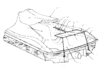
[00047] Figs. 1A and 1B show a "hammerhead" design having longitudinal and
transverse frame portions, shown with (Fig.1B) and without (Fig. 1A)
additional
strapping. Figs. 1A and 1B additionally illustrate a seat 2 of the PWC 1;
inner
fasteners 3, outer fasteners 4, and a known type of water ski/tow hook
mounting
apertures 5 in the rear 6 of the PWC seat 2; the hull 7 of the PWC; one or
more
strap connecting positions 8 on the bracket; one or more straps 9; and known
lifting hooks 10 in PWC transom 11. The PWC has a rear deck D where
passengers normally ride or sit.
[00048] In Figs. 1A and 1B, the bracket 101 is a continuous wire frame that
may
be formed by a rod, of hollow or solid cross-section, either a continuous rod
or
multiple rod sections assembled into a continuous frame. While a uniform,
constant diameter/thickness is shown for the rod frame of bracket 101, the
diameter or thickness could vary over the perimeter of the frame. Bracket 101
includes a first front longitudinal leg 103 and a second front longitudinal
leg 105
CA 02831209 2013-10-29
ISA-001-A
(generally parallel to the longitudinal axis of the PWC). Longitudinal legs
103
and 105 are substantially parallel to one another and extend from the water
ski
mounting hook apertures 5. In the hammerhead version of Figs. 1 A and 1B,
longitudinal legs 103 and 105 terminate at the bracket front end in free ends
103a
and 105a (best shown in Figs. 6 through 10, and common to all of the
illustrated
embodiments) secured in mounting apertures 5 in the rear seat 2 of the PWC,
for
example with inner and outer fasteners 3 and 4 in a manner similar to the
original
ski/tow hook structure, or with any other connecting structure or method
including, but not limited to, structural adhesives. Longitudinal bracket legs
103
and 105 terminate at their rear ends where the frame extends laterally to form
a
substantially rectangular enlarged storage portion which includes a first
front
transverse section 107 (transverse to the longitudinal axis of the PWC)
connected
to the first front longitudinal leg 103, and a second front transverse section
109
connected to the second longitudinal leg 105. The first front transverse
section
107 is connected to a first back longitudinal section 111, and the second
front
transverse section 109 is connected to a second back longitudinal section 113.
The first back longitudinal section 111 and the second back longitudinal
section
113 are connected to the back transverse section 115.
[00049] In Fig. 1B, the back transverse section 115 of bracket 101 is shown
with
optional straps 9 secured to the bracket at strap connection positions 8 (in
the
illustrated embodiment, the corners of the hammerhead area). The straps 9 are
connected at their lower ends to the lifting hooks 10 which are commonly found
attached to or adjacent the transom 11. Straps 9 may reduce the tendency of
the
11
CA 02831209 2013-10-29
ISA-001-A
cantilevered frame to vibrate or bounce in rough seas; as such they are not a
support for the frame, but rather function as a tensioning device.
[00050] The bracket shown in Figs. 1A and 1B is mounted in cantilever fashion
to
the rear of seat 2 of the PWC by the front ends of longitudinal legs 103 and
105,
which form the free or terminal ends of the substantially rigid bracket frame.
The
remainder of the bracket 101, which is generally planar (in a single plane),
is
located above deck D, preferably parallel to the deck although different
angular
orientations are possible.
[00051] Figs. 1A and 1B show clip-type spacers 100 connected between legs 103
and 105, for example made from wire ovals or molded plastic pieces with
apertures for legs 103 and 105 to pass through. Clips 100 may be used to add
rigidity to the stem portion of the frame defined by legs 103 and 105, or may
be
used to partition the storage area defined between legs 103 and 105 to better
retain/secure items such as fishing rod handles and the like placed therein.
Clips
100 are also shown in subsequent Figures.
[00052] Fig. 2A illustrates a short, narrow bracket 12 that consists
essentially of
the longitudinal stem portion of the hammerhead design of Figs. IA and 1B,
comprising legs 103 and 105 formed by a rod which forms a narrow, elongated U-
shape. The longitudinal legs terminate at the rear end of the bracket in a
rounded
bight 104, rather than extending transversely into an enlarged hammerhead
region. Fig. 2A also shows optional stabilizing straps 201 connected at one
end to
the inner end of the bracket 12 adjacent the rear 6 of seat 2, and connected
at their
other end to a rear portion of seat 2, for example a handle of known type, a
hook
12
CA 02831209 2013-10-29
ISA-001-A
or cleat, or some other convenient mounting point above the bracket at the
rear of
the seat. Straps 201 may be used to stabilize the bracket against swaying
motion,
and to prevent the bracket from bouncing in heavy waves. Straps 201 also help
support the weight of any equipment mounted on bracket 12. Straps 201 may be
made of any material, including but not limited to plastic tie wraps, nylon
straps,
and metal strapping, and may be flexible or more or less rigid. While two
straps
201 are shown, with one strap connected to each leg of the bracket, a single
strap
201 might be looped around or otherwise connected to the legs of the bracket.
Straps 201 preferably run vertically from the inner end of the bracket 12 to
an
overlying connection point on the rear of the seat, so as not to interfere
with
access to equipment stored in or mounted on the bracket.
[00053] Fig. 2B illustrates a double-length bracket 13 similar to bracket 12
in Fig.
2A, only longer. Straps 201 are also shown in use with the bracket of Fig. 2B,
and it should be understood that straps 201 could be used with any of the
brackets
described herein.
[00054] Figure 3 illustrates a bracket 17 formed by a rod including a first
front
longitudinal inclined leg 301 and a second front longitudinal inclined leg 303
in a
spaced relationship with the first longitudinal inclined leg 301. The front
longitudinal inclined leg 301 and the front longitudinal inclined leg 303 are
inclined relative to rear longitudinal leg portions 301a and 303a at an acute
angle.
Bracket 17 is accordingly a multi-planar version of brackets 12 and 13 in
Figs. 2A
and 2B, with front leg portions 301 and 303 lying in a first plane, and rear
leg
portions 301a and 303a lying in a second plane set at an acute angle to the
first
13
CA 02831209 2013-10-29
ISA-001-A
plane. Either plane may be at an acute angle with respect to the deck of the
PWC,
depending whether the free ends of the front leg portions are mounted in the
apertures 5 in the PWC rear seat as in Figs. 1A through 2B, or in apertures 5
in
deck D. In the illustrated example of Fig. 3, first longitudinal inclined leg
301
and the second longitudinal inclined leg 303 are acutely angled (e.g., 45 or
so)
relative to deck D, and connect to a U-shaped section 304 formed by rear leg
portions 301a and 303a that is substantially parallel to the back deck D.
[00055] In Fig. 4A, an alternate bracket 401 comprises a rod structure
including a
first front longitudinal section 403 which may be substantially L-shaped and a
second front longitudinal section 405 (parallel to the longitudinal axis of
the
PWC) which may be substantially L-shaped and which is substantially
parallel to the first front longitudinal section 403 and the which extends
from the
aperture 5 and further extends to a substantially rectangular enlarged head
portion
in a different plane than the horizontal portions of legs 403 and 405. The
enlarged
head portion includes a first front transverse section 407 (transverse to the
longitudinal axis of the PWC) connected to the first front longitudinal
section 403
and a second front transverse section 409 connected to the second longitudinal
section 405. The first front transverse section 407 is connected to a first
back
longitudinal section 411, and the second front transverse section 409 is
connected
to a second back longitudinal section 413. The first back longitudinal section
411
and the second back longitudinal section 413 are connected to the back
transverse
section 415. The substantially rectangular portion may optionally include one
or
more downward extending arms or leg 417 to connect or support the
substantially
14
CA 02831209 2013-10-29
ISA-001-A
rectangular portion to or on the deck D of the PWC. Depending on the weight
and rigidity of the rod material used for the bracket, legs 417 may not be
needed,
and the enlarged head portion comprising sections 407 - 418 may be suspended
above deck D by legs 403 and 405.
[00056] In Fig. 4B, the back transverse section 418 of the bracket 401 is
shown
with optional straps 9 secured to the bracket at strap connection positions 8
(in the
illustrated embodiment, the corners of the enlarged head area). The straps 9
are
connected at their lower ends to the lifting hooks 10 which are commonly found
attached to or adjacent the transom 11.
[00057] Fig. 5A illustrates a bracket 16 which may be a rod which may be in
the shape of a discontinuous rectangle with an inverted longitudinal "stem"
portion
507, 509, and which may include a front traverse section 501 which may be
connected to an opposing pair of side longitudinal sections 503 which may be
connected to an opposing pair of back traverse sections 505 which may be
connected
to a pair of opposing back longitudinal sections 507 which may be connected to
a pair
of opposing inclined longitudinal sections 509 which may form an acute angle
with
respect to the deck and which may be connected to the deck of the PWC. The
bracket 16 may be mounted on downward extending arms 517 which may support the
bracket 16 on the deck of the PWC.
[00058] Fig. 5B illustrates one or more optional straps 9 extending between a
strap
connecting point 8 to lifting hooks 10.
[00059] Fig. 6 illustrates a perspective view of a bracket 1101 similar to
bracket
101 in Fig. 1B, but with a modified triangular head portion.
CA 02831209 2013-10-29
ISA-001-A
[00060] Fig. 7 illustrates a perspective view of the bracket of Fig. 2B.
[00061] Fig. 8 illustrates a perspective view of bracket of Fig. 3.
[00062] Fig. 9 illustrates a perspective view of the bracket of Fig. 4B.
[00063] Fig. 10 illustrates a perspective view of the bracket of Fig. 5B.
[00064] In Fig. 11, the bracket 1101 comprises a rod structure with an
enlarged
head portion in the shape of a discontinuous triangle and which includes a
first
front longitudinal section 1103 and a second front longitudinal section 1105
(parallel to the longitudinal axis of the PWC) substantially parallel to the
first
front longitudinal section 1103 and the which extends from the aperture and
further extends to a substantially continuous triangular enlarged head portion
including a first front angled section 1107 (angled at an acute angle to the
longitudinal axis of the PWC) connected to the first front longitudinal
section
1103 and a second front angled section 1109 (angled at an acute angle to the
longitudinal axis of the PWC) connected to the second longitudinal section
1105.
The first front angled section 1107 is connected to a back transverse section
1111,
and the second front angled section 1109 is connected to the back transverse
section 1111.
[00065] While the invention is susceptible to various modifications and
alternative forms, specific embodiments thereof have been shown by way of
example in the drawings and are herein described in detail. It should be
understood, however, that the description herein of specific embodiments is
not
intended to limit the invention to the particular forms disclosed.
16
CA 02831209 2013-10-29
ISA-001-A
Description of Operation
[00066] In operation, the bracket as illustrated in the examples of Figs. 1A -
11 is
used by mounting it to a PWC, primarily by securing the free ends of the
longitudinal legs or stem portion of the bracket in existing mounting holes
formed
in the rear seat or rear deck of the PWC, and secondarily if desired by
securing
tensioning straps to rear portions of the bracket frame and to hooks or cleats
in the
lower rear of the PWC below the bracket. Sporting, safety, and recreational
equipment can then be secured directly to portions of the bracket frame about
the
perimeter of the bracket, either inside or outside the frame, for example with
rope,
clips, cable, or ties; or, the equipment may simply be placed within the frame-
enclosed interior storage area of the bracket, including both the narrower
longitudinal "stem" and the wider transverse "head" regions, the equipment
resting on the deck and constrained by the frame from shifting longitudinally
or
laterally about the deck.
[00067] It will finally be understood that the disclosed embodiments represent
presently preferred examples of how to make and use the invention, but are
intended to enable rather than limit the invention. Variations and
modifications of
the illustrated examples in the foregoing written specification and drawings
may
be possible without departing from the scope of the invention. It should
further
be understood that to the extent the term "invention" is used in the written
specification, it is not to be construed as a limiting term as to number of
claimed
17
CA 02831209 2013-10-29
ISA-001-A
or disclosed inventions or discoveries or the scope of any such invention or
discovery, but as a term which has long been conveniently and widely used to
describe new and useful improvements in science and the useful arts. The scope
of the invention should accordingly be construed by what the above disclosure
teaches and suggests to those skilled in the art, and by any claims that the
above
disclosure supports in this application or in any other application claiming
priority
to this application.
18