Note : Les descriptions sont présentées dans la langue officielle dans laquelle elles ont été soumises.
CA 02831537 2013-09-26
CA Application
Wakes Ref 10549/00002
1 CATALYST FOR DECOMPOSITION OF HYDROCARBON OIL AND
METHOD FOR DECOMPOSING HYDROCARBON OIL
3
4 TECHNICAL FIELD
100011 The present invention relates to a hydrocarbon oil cracking
6 catalyst and a method for cracking hydrocarbon oil, and in particular, to
a
7 catalyst that is used in cracking hydrocarbon oil to produce lighter oil
8 without feeding hydrogen from the outside of the system, as well as a
9 method for cracking hydrocarbon oil by using the catalyst.
0
ii BACKGROUND ART
12 10002) Conventionally, hydrocracking, thermal cracking and fluid
13 catalytic cracking are known as methods for producing light hydrocarbon
14 oil which is useful as a feedstock for petrochemicals, fuel oil and so
on,
is and light hydrocarbon gas which is useful as fuel gas and so on, by
cracking
16 heavy hydrocarbon oil to produce lighter oil.
17 00031 Here, hydrocracking is a process in which heavy
hydrocarbon
18 oil is cracked to produce lighter oil by bringing the heavy hydrocarbon
oil
19 into contact with a hydrogenation catalyst in a hydrogen atmosphere at
20 elevated temperature and pressure (see, for example, JP 2008-297452 A
21 (PIT I)). In addition, thermal cracking is a process used to produce
lighter
22 oil from heavy hydrocarbon oil under an elevated temperature condition
by
23 means of pyrolysis of hydrocarbon molecules without the aid of catalyst
24 (see, for example. JP 2009-102471 A (PTL 2)). Further, fluid catalytic
25 cracking is a process used to produce lighter oil from heavy hydrocarbon
oil
26 by bringing the heavy hydrocarbon oil into contact with a fluidized
catalyst
27 (see, for example, JP 8-269464 A (PTL 3)).
28
29 CITATION LIST
30 Patent Literature
31 100041 PTL 1: JP 2008-297452 A
32 PTL 2: JP 2009-102471 A
22447577,1
CA 02831537 2013-09-26
CA Application
Blakes Ref :10549/00002
PTL 3: JP 8-.269464 A
3 SUMMARY OF INVENTION
4 (Technical Problem)
100051 The hydrocracking has a drawback, however, in that it uses a
6 large amount of high pressure hydrogen gas for cracking reaction and thus
7 requires large facilities for producing hydrogen gas, leading to
increased
8 cost. The thermal cracking also has a drawback in that it produces a
large
9 amount of coke with little aromatic ring cleavage, leading to inefficient
manufacture of light hydrocarbon oil and inadequate cracking of heavy
11 hydrocarbon oil. Further, the fluid catalytic cracking has a drawback in
12 terms of high operational costs of devices,
13 [00061 Additionally, the hydrocracking requires proactive
14 desulfurization and denitrogenation of heavy hydrocarbon oil in order to
prevent deterioration (poisoning) of a hydrogenated catalyst. Further, due
16 to little desulfurization and denitrogenation reaction of hydrocarbon
oils,
17 both the thermal cracking and the fluid catalytic cracking require, as
is the
18 case with the hydrocracking, proactive desulfurization and
denitrogenation
19 of heavy hydrocarbon oils. That is, the hydrocracking, thermal cracking
and fluid catalytic cracking have the disadvantage of the necessity of
21 pretreatment of heavy hydrocarbon oils.
22 100071 Therefore, an object of the present invention is to
provide a
23 hydrocarbon oil cracking catalyst that allows efficient production of
lighter
24 oil from hydrocarbon oil at low cost, without performing proactive
desulfurization and denitrogenation of the hydrocarbon oil and without
26 using high pressure hydrogen gas, and a method for cracking hydrocarbon
27 oil.
28 (Solution to Problem)
29 [00081 The inventors of the present invention have made
intensive
studies to address the above-described problems and found that hydrocarbon
3 I oil can be cracked efficiently. without using hydrogen gas, in the
presence
32 of water by using a catalyst composed of an oxide having a specific
crystal
2
22447577.1
CA 02831537 2013-09-26
CA Application
Blakes Ref: 10549100002
structure. The present invention has been completed based on this finding..
2 100091 That is, an object of the present invention is to
advantageously
3 solve the above-described problems, and the present invention provides a
4 hydrocarbon oil cracking catalyst used in cracking hydrocarbon oil in the
presence of water, the catalyst composed of an oxide having a perovskite-
6 type structure or an oxide having a pseudobrookite-type structure, or a
7 mixture thereof.
8 (00101In the hydrocarbon oil cracking catalyst according to the
9 present invention, the oxide having a perovskite-type structure is
preferably
represented by the following general formula:
12 [where A is an element selected from the group consisting of a Group IA
13 element, a Group ILA element, a Group WA element and a Group VM
14 element, A' is at least one element selected from the group consisting
of a
IS Group VA element and a Group IIIB element, B is an element selected from
16 the group consisting of a Group 1113 element and a Group IVA element,
and
17 B' is at least one element selected from the group consisting of a Group
VA
IS element and a Group II1B element, in which A, A', B and B' are different
19 from one another, x is in the range of 0 5_ x 5_ 0.4, y is in the range
of 0 y
and 8 represents oxygen deficiency].
21 Additionally, with the hydrocarbon oil cracking catalyst according to
the
22 present invention, it is further preferred that the A is nickel or
cobalt, the B
23 is titanium, and the B' is aluminum or vanadium.
24 Moreover, with the hydrocarbon oil cracking catalyst according to the
present invention, it is further preferred that x = 0.
26 100111 Furthermore, with the hydrocarbon oil cracking catalyst
27 according to the present invention, it is preferred that the oxide
having a
28 pseudobrookite-type structure is Fe2Ti05.
29 100121 in addition, an object of the present invention is to
advantageously solve the above-described problems, and the present
3 i invention provides a method for cracking hydrocarbon oil, including
32 bringing the hydrocarbon oil into contact with any of the hydrocarbon
oil
3
22447577.1
CA 02831537 2013-09-26
CA Application
Blakes Ref: 10549/00002
1 cracking catalysts according to the aforementioned aspects in the
presence
2 of water to thereby crack the hydrocarbon oil.
3 (Effect of Invention)
4 10013] The hydrocarbon oil cracking catalyst and the method for
cracking hydrocarbon oil according to the present invention enable efficient
6 production of lighter oil from hydrocarbon oil at low cost, without
7 performing proactive desulfurization and denitrogenation of the feedstock
8 hydrocarbon oil and without using high pressure hydrogen gas.
9
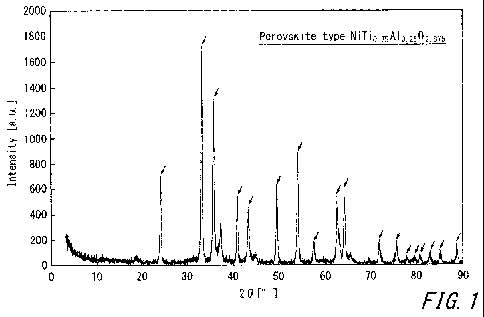
to BRIEF DESCRIPTION OF THE DRAWING
Ii 100141 FIG. I illustrates an X-ray diffraction spectrum of
12 NiTio,75A10.2502.875 baying a perovskite-type structure.
13 FIG. 2 illustrates an X-ray diffraction spectrum of NiTiO3
14 having a perovskite-type structure.
FIG. 3 illustrates an X-ray diffraction spectrum of
16 CoTi0.75V0,2503.125 having a perovskite-type structure.
I? FIG. 4 illustrates an X-ray diffraction spectrum of Fe2TiO5
18 having a pseudobrookite-type structure.
19 FIG. 5 illustrates an X-ray diffraction spectrum of a mixture of
NiO and rutile-type
21 FIG. 6 illustrates an X-ray diffraction spectrum of a mixture of
22 Fe203, rutile-type TiO2 and anatase-type Ti02.
23
24 DESCRIPTION OF EMBODIMENTS
1001.5] Embodiments of the present invention will now be described in
26 detail below. A hydrocarbon oil cracking catalyst according to the
present
27 invention is used in cracking hydrocarbon oil to produce lighter oil.
28 Additionally, a method for cracking hydrocarbon oil according to the
29 present invention involves bringing hydrocarbon oil into contact with
hydrocarbon oil cracking catalyst in the presence of water, without feeding
3 i hydrogen from the outside of the reaction system, thereby cracking the
32 hydrocarbon oil to produce light hydrocarbon oil.
4
22447577.1
CA 02831537 2013-09-26
CA Application
Blakes Ref 10549/00002
1 l0016] As used herein, examples of the hydrocarbon oil to be
cracked
2 (to produce lighter oil therefrom) by using the hydrocarbon oil cracking
3 catalyst according to the present invention may be heavy hydrocarbon oils
4 including, but not limited to, atmospheric distillation residues and
reduced-
pressure distillation residues generated during petroleum refining. Specific
6 examples of the hydrocarbon oil to produce lighter oil therefrom by using
7 the hydrocarbon oil cracking catalyst may include hydrocarbon oil with a
50
8 vol /0 distillation temperature in atmospheric distillation (T50) of 150
C or
9 higher and 550 C or lower, a hydrocarbon oil with 150 of 200 C or
higher
and 550 C or lower, and a hydrocarbon oil with T50 of 250 C or higher
ii and 550 C or lower.
12 10017-1 Additionally, the hydrocarbon oil cracking catalyst
according to
13 the present invention composed of an oxide having a perovskite-type
14 structure, or an oxide having a pseudobrookite-type structure, or a
mixture
of an oxide having a perovskite-type structure and an oxide having a
16 pseudobrookite-type structure.
17 10018] It should be noted that the crystal structure of oxides
may be
18 assessed by, for example, X-ray diffraction analysis. Specifically,
whether
19 an oxide has a perovskite-type structure can be determined by whether
peaks specific to the perovskite-type structure appears in the X-ray
21 diffraction spectrum. In addition, whether an oxide has a pseudobrookite-
22 type structure can be determined by whether peaks specific to the
23 pseudobrookite-type structure appears in the X-ray diffraction spectrum.
24 100191 In this case, an oxide having a perovskite-type structure
and an
oxide having a .pseudobrookite-type structure are used as the hydrocarbon
26 oil cracking catalyst based on a novel finding revealed by the inventors
of
27 the present invention that these Oxides allow, when used as the
catalyst,
28 efficient cracking of hydrocarbon compounds using water as hydrogen
29 source. Although the mechanism by which hydrocarbon compounds can be
efficiently decomposed with the use of these oxides as the catalyst is not
31 known, it is inferred that this is because an oxide having a perovskite-
type
32 structure and an oxide having a pseudobrookite-type structure have a
high
5
22447577.1
CA 02831537 2013-09-26
CA Application
Blakes Ref: 10549/00002
1 ability to decompose water to produce oxygen and hydrogen because of
2 their high lattice oxygen supply rate. That is, it is inferred that this
is
3 because, in cracking a hydrocarbon compound using water as hydrogen
4 source, a portion of the hydrocarbon compound is allowed to react with
water as shown in the following reaction formula to thereby promote the
6 generation of hydrogen as hydrogen source:
7 CnHm + 2111120 nCO2 + (2n + (m/2)) H2
8 100201 Additionally, examples of the oxide having a perovskite-
type
9 structure may include a composite oxide represented by a general formula:
ABO3, and a composite oxide with a portion of at least one of an A-site
It element and a B-site element of the composite oxide ABO3 substituted by
12 other elements. Specific examples of the oxide having a perovskite-type
13 structure may include an oxide represented by the following general
14 formula (1):
A i_xtit xB _ylVy03-6 .. (1)
16 [where A is an element selected from the group consisting of a Group IA
17 element, a Group HA element, a Group IIIA element and a Group VIII
18 element, A' is at least one element selected from the group consisting
of a
19 Group VA element and a Group IIIB element, B is an element selected from
the group consisting of a Group MB element and a Group IVA element, and
21 B' is at least one element selected from the group consisting of a Group
VA
22 element and a Group IIIB element, in which A, A'. B and B' are different
23 from one another, x is in the range of 0 x 0.4, y is in the range of 0
5. y
24 5Ø4, and 6 represents oxygen deficiency].
As used herein, the oxygen deficiency corresponds to a number which
26 makes the oxide represented by the general formula (1) electrically
neutral.
27 100211 As mentioned above, the oxide having a iperovskite-type
28 structure may be a composite oxide with partial substitution of an A-
site
29 element and a B-site
element by other elements A' and or a composite
oxide without substitution of an A-site element and a B-site element.
31 100221 in this regard, when an oxide with partial substitution
of the A-
32 site element and the B-site element by other elements A' and B' is used,
the
6
22447577,1 .
CA 02831537 2013-09-26
CA Application
Blakes Ref: 10549/00002
element A' preferably has an atomic ratio x of 0.4 or less (x 5. 0.4). and
2 more preferably x = 0 (i.e.. only the B-site element is substituted,
while the
3 A-site element is not substituted). In addition, the element B'
preferably
4 has an atomic ratio y of 0.4 or less (y 5 0.4). more preferably 0.35 or
less
(y .5 0.35), and particularly preferably 0.25 or less (y 5. 0.25). This is
6 because if the atomic ratio of these elements A' and B' is too large, the
7 perovskite-type structure may be difficult to maintain.
8 In addition, the B-site element is preferably an element selected from
Group
9 IIIB elements when the A-site element is a Group IIIA element. Further,
the B-site element is preferably an element selected from Group IVA
11 elements when the A-site element is a Group IA element, a Group hA
12 element or a Group VIII element.
13 100231 In the aforementioned oxide having a perovskite-type
structure
14 represented by the general formula (I), particularly, the element A may
be,
for example, nickel. cobalt or barium. In addition, the element B may be,
16 for example, zirconium, cerium or titanium. Further, the element B' may
17 be, for example, aluminum or vanadium.
is 100241 In the aforementioned oxide having a perovskite-type
structure
19 represented by the general formula (1), the element A is preferably, for
example, nickel or cobalt. In addition, the element B is preferably, for
21 example, zirconium, cerium or titanium. Further, the element B' is
22 preferably, for example, aluminum or vanadium. The reason is that since
23 the hydrocarbon oil cracking catalyst according to the present invention
is
24 used in the presence of water, the elements constituting the oxide are
preferably such elements that have a low ionization tendency and are stable
26 in water; for example, transition metal elements.
27 100251 It should be noted that the oxide (composite oxide)
having a
28 perovskite-type structure as mentioned earlier may be prepared by,
without
29 any particular limitation, for example, a coprecipitation process in the
following manner.
31 (i) Firstly, a compound containing an element A and a compound
32 containing an element B, and, optionally, a compound containing an
element
7
22447577.1
CA 02831537 2013-09-26
CA Application
Blakes Ref 10549/00002
A' and a compound containing an element B' are dissolved in ion-exchanged
2 water in amounts such that, for example, A'/A is in the range of 0 to
2./3 (in
3 molar ratio) and 11'/B is in the range of 0 to 2/3 (in molar ratio) to
prepare
4 an aqueous solution containing the elements A and B as well as the
optional
elements A' and
6 (ii) Then, a coprecipitating agent, such as ammonia water and a sodium
7 carbonate solution, is added dropwise to the prepared aqueous solution
8 while adjusting the pH of the aqueous solution so as not to shift toward
the
9 alkaline side (e.g., so that the pH is maintained at 5 to 8) to thereby
form. a
coprecipitate containing the elements A and B as well as the optional
ti elements A' and B'.
12 (iii) Finally, the resulting precipitate is filtered and dried, and the
dried
13 precipitate is calcined to obtain a composite oxide having a perovskite-
type
14 structure.
In the above step (iii), the precipitate is preferably dried at a temperature
16 of 100 C or higher in terms of efficient evaporation of moisture
therefrom.
17 Furthermore, the precipitate is preferably dried at a temperature of 160
C
18 or lower from the viewpoint of preventing rapid drying thereof. In
9 addition, the dried precipitate is preferably calcined at a temperature
of 500
C.: or higher in terms of ensuring the structural stability of the produced
21 composite oxide (catalyst) (i.e.., reducing structural changes in the
22 composite oxide when used as the catalyst to crack hydrocarbon oil).
23 Furthermore, the precipitate is preferably calcined at a temperature of
900
24 C or lower from the viewpoint of alleviating the reduction of the
surface
area of the produced composite oxide.
26 100261 In addition, examples of the oxide having a
pseudobrookite-type
27 structure as the hydrocarbon oil cracking catalyst according to the
present
28 invention may include, without any particular limitation. Fe2Ti05, which
is
29 a composite oxide.
100271 It should be noted that Fe2TiO5 having a pseudobrookite-type
31 structure may be prepared by, without any particular limitation, for
32 example, a coprecipitation process in the following manner.
8
22447577.1
CA 02831537 2013-09-26
CA Application
Blakes Ref: 1050100002
1 (iv) Firstly, a compound containing Fe and a compound containing Ti are
2 dissolved in ion-exchanged water in amounts such that Fe:Ti = 2:1 (in
molar
3 ratio) to prepare an aqueous solution containing Fe and Ti.
4 (v) Then, a coprecipitating agent, such as ammonia water and a sodium
carbonate solution, is added dropwise to the prepared aqueous solution
6 while adjusting the pH of the aqueous solution so as not to shift toward
the
7 alkaline side (e.g., so that the pH is maintained at 5 to 8) to thereby
form a
8 c precipitate containing Fe and Ti.
9 (vi) Finally, the resulting precipitate is filtrated and dried, and the
dried
io precipitate is calcined to obtain Fe2TiO5 having a pseudobrookite-type
1 1 structure.
12 In the above step (vi), the precipitate is preferably dried at a
temperature of
13 100 C or higher in terms of efficient evaporation of the water.
14 Furthermore. the precipitate is preferably dried at a temperature of 160
C
or lower from the viewpoint of preventing rapid drying of the precipitate.
16 in addition, the dried precipitate is preferably calcined at a
temperature of
17 500 '12 or higher in terms of ensuring the structural stability of the
18 produced composite oxide (catalyst) (i.e., reducing structural changes
in the
19 composite oxide when used as the catalyst to crack a hydrocarbon oil).
Furthermore, the precipitate is preferably calcined at a temperature of 900
21 C or lower from the viewpoint of alleviating the reduction of the
surface
22 area of the produced composite oxide.
23 100281 In this regard, the aforementioned oxide having a
perovskite-
24 type structure and the aforementioned oxide having a. pseudobrookite-
type
structure may also be prepared by known methods other than the
26 coprecipitation process, such as a sol-gel process.
27 [00291 Additionally, a method for cracking hydrocarbon oil
according
28 to the present invention involves bringing hydrocarbon oil into contact
with
29 the aforementioned hydrocarbon oil cracking catalyst in the presence of
water to thereby crack the hydrocarbon oil. Specifically, in the method for
31 cracking hydrocarbon oil according to the present invention, for
example, a
32 mixture of hydrocarbon oil and water is allowed to flow into a reactor
9
22447577.1
CA 02831537 2013-09-26
CA Application
Blakes Ref: 10549/00002
loaded with the catalyst. thereby causing the catalyst, the hydrocarbon oil
2 and the water to contact one another so as to crack the hydrocarbon oil.
3 [0030] In this process, water used in the cracking of the
hydrocarbon
4 oil is utilized as hydrogen source when hydrocarbon compounds contained
in the hydrocarbon oil with a high molecular weight are cracked to produce
6 hydrocarbon compounds with a lower molecular weight, i.e., when lighter
7 oil is produced from the hydrocarbon oil. Accordingly, it suffices to use
8 water in an amount sufficient to produce lighter oil from hydrocarbon
oil.
9 For example, it is desirable that water is added by 5 parts by mass to
2000
parts by mass, preferably by I 0 parts by mass to 1000 parts by mass, and
ii more preferably by 10 parts by mass to 500 parts by mass, per 100 parts
by
12 mass of the hydrocarbon oil. This is because if water is added by less
than
13 5 parts by mass per 100 parts by mass of the hydrocarbon oil, it may not
be
14 possible to produce lighter oil from the hydrocarbon oil sufficiently
due to
the shortage of hydrogen source. On the other hand, if water is added by
16 more than 2000 parts by mass, a greater amount of water may fail to
17 contribute to the production of lighter oil from hydrocarbon oil,
resulting in
18 an increase in cost and a reduction in the cracking efficiency of the
19 hydrocarbon oil (i.e., production efficiency of light hydrocarbon oil).
[00311 Additionally, in the method for cracking hydrocarbon oil
21 according to the present invention, the conditions under which the
mixture
22 of the hydrocarbon oil and water is brought into contact with the
catalyst in
23 the reactor may be changed appropriately.
24 Specifically, the mixture and the catalyst may be brought into contact
with
each other at a relatively low temperature, e.g., at 300 C to 600 C,
26 preferably at 350 C to 550 C, and more preferably at 400 C to 500 C.
If
27 the temperature is lower than 300 C, the cracking reaction of the
28 hydrocarbon oil may not proceed sufficiently due to activation energy
29 insufficient for the reaction. Alternatively, if the temperature is
higher
than 600 C, unnecessary gases (such as methane and ethane) may be
31 produced in large amounts, reducing the cracking efficiency of the
32 hydrocarbon oil.
22447577.1
CA 02831537 2013-09-26
CA Application
Blakes Ref 10549/00002
In addition, the mixture and the catalyst may be brought into contact with
2 each other at a pressure of, for example, 0.1 MPa to 40 MPa, preferably
0.1
3 MPa to 35 MPa, and more preferably 0.1 MPa to 30 MPa. if the pressure is
4 less than 0.1 MPa, it may be difficult to allow the hydrocarbon oil and
water to flow into the reactor smoothly. Alternatively, if the pressure is
6 more than 40 MPa, the reactor may be more costly to manufacture.
7 Further, the mixture may be allowed to flow into the reactor loaded with
the
8 catalyst at a liquid hourly space velocity (LHSV) of, for example, 0.01
11-1
9 to 10 WI, preferably 0.05 ICI to 5 WI, and more preferably 0.1 11-1 to 2
WI.
JO One reason is that when the liquid hourly space velocity is less than
0.01 h-
t 1 , unnecessary gases may be produced predominantly, resulting in a
12 reduction in the cracking efficiency of the hydrocarbon oil. Another
reason
13 is that when the liquid hourly space velocity is more than 10 11-1. the
14 reaction time may be too short to allow the cracking reaction of the
hydrocarbon oil to proceed sufficiently.
16 100321 As mentioned above, in the method for cracking
hydrocarbon oil
17 according to the present invention, hydrogen that is necessary for the
18 cracking reaction of the hydrocarbon oil may be supplied from the water
19 present in the system. Accordingly, in the method for cracking
hydrocarbon
oil according to the present invention, there is no need to add hydrogen
21 from the outside of the system, where a molar ratio of the amount of
22 hydrogen to be added from the outside of the system to the supply amount
23 of the hydrocarbon oil to be cracked (the addition amount of hydrogen I
the
24 supply amount of the hydrocarbon oil) may be 0.1 or less, and preferably
0.
Therefore, according to the method for cracking hydrocarbon oil of the
26 present invention using the hydrocarbon oil cracking catalyst of the
present
27 invention, it is possible to crack hydrocarbon oil at low cost in an
efficient
28 manner to obtain light hydrocarbon, without using high pressure hydrogen
29 gas.
100331 Specifically, according to the method for cracking hydrocarbon
31 oil of the present invention, for example, heavy hydrocarbon oil that is
32 composed of a mixture of various hydrocarbon compounds including a
11
22447577.1
CA 02831537 2013-09-26
CA Application
Blakes Ref: 10549/00002
1 condensed polycyclic-aromatic compound, such as 1-methylnaphthalene,
2 quinoline, anthracene and phenanthrene. and a non-condensed polycyclic-
3 aromatic compound, such as dibenzothiophene and biphenyl, may be cracked
4 to obtain light hydrocarbon oil with a weight-average molecular weight
which is half or less of, preferably a third or less of that of the heavy.
6 hydrocarbon oil. That is, light hydrocarbon oil may be produced by
causing
7 cleavage of aromatic rings of the hydrocarbon compounds in the heavy
8 hydrocarbon oil with a very high probability to obtain monoaromatic
9 compounds. As used herein, the weight-average molecular weight refers to
ia a weight-average molecular weight in terms of polystyrene as measured by
it gel permeation chromatography (CiPC).
12 100341 In addition, since the hydrocarbon oil cracking catalyst
of the
13 present invention is less prone to deterioration, according to the
method for
14 cracking hydrocarbon oil of the present invention using this catalyst,
there
is no need to perform proactive desulfurization and denitrogenation of the
16 feedstock hydrocarbon oil to be cracked.
17 100351 While the embodiments of the present invention have been
18 described, the hydrocarbon oil cracking catalyst and the method for
19 cracking hydrocarbon oil according to the present invention are not
limited
to the disclosed embodiments, and numerous changes may be made thereto
21 as appropriate.
/ 2
23 EXAMPLES
24 100361 The present invention will be described in more detail
below
with reference to examples thereof in a non-limiting way.
26 100371 (Example 1)
27 A catalyst composed of an oxide having a perovskite-type structure with
an
28 element A of nickel, an element B of titanium and an element IV of
29 aluminum was prepared. Specifically. at first, nickel nitrate
hexahydrate,
titanium sulfate and aluminum nitrate were dissolved in ion-exchanged
31 water with Ni:Ti:Al = 1:0.75:0.25 (in molar ratio) to obtain an aqueous
32 solution. Then, a sodium carbonate solution was added dropwise to the
12
22447577.1
CA 02831537 2013-09-26
CA Application
Makes Ref: 10549100002
1 obtained aqueous solution while adjusting the pH of the aqueous solution
so
2 as not to exceed 7 to produce a precipitate. Finally, the resulting
3 precipitate was allowed to be aged (stand still for one hour), then
filtered
4 and dried (at 150 ( for one hour), after which the dried precipitate was
calcined at a temperature of 800 C to prepare a catalyst composed of a
6 composite oxide.
7 Meanwhile, the resulting composite oxide was analyzed by an X-ray
8 diffractometer, and the obtained results are as shown in an X-ray
diffraction
9 spectrum as illustrated in FIG. 1 with diffraction peaks specific to
0 NiTi0.75A10.2502.875 having a perovskite-type structure (as indicated by
11 arrows in the figure). That is, it was found that the prepared catalyst
is
12 NiTi0.75A10.2502.875 having a perovskite-type structure.
13 Then, the prepared catalyst was loaded into a stainless reactor (with
inner
14 volume of 10 .mL) with a bulk density of 0.908 gicm3. Then, the interior
of
the reactor loaded with the catalyst was heated and pressurized to a
16 temperature of 470 C and a pressure of 0.10 MPaG, while feeding ion-
17 exchanged water into the reactor at a flow rate of 0.1 mLimin.
]8 Subsequently, without feeding hydrogen, heavy hydrocarbon oil having
19 characteristics as shown in Table 1 (oils distilled from a thermal
cracker)
and ion-exchanged water were allowed to continuously flow into the reactor
21 (for both the ion-exchanged water and the heavy hydrocarbon oil, the
flow
22 rate was 0.1 mL/min and LHSV was 0.6 h-1). Then, after two hours from
23 the start of oil-flowing, the effluents from the reactor (the cracking
reaction
24 products) were collected over three hours to calculate the cracking rate
of
the heavy hydrocarbon oil as described below. The results thereof are
26 shown in Table 2.
27
13
22447577.1
CA 02831537 2013-09-26
CA Application
Makes Ref: 10549/00002
1 [0038] [Table 1]
Characteristics Analysis
Method
Density (at 15 C) [g/cm3] 0.9737 JIS K 2249
Sulfur Content [mass%] 2.4 JIS K 2541 I
Nitrogen Content imass%1 0.19 JIS K 2609
Kinematic Viscosity (at 50 C) 11.7 JIS K 2283
[mm2/s)
Kinematic Viscosity (at 100 'C.) 3.338
=
:mm2/s._
105% _________________________________ 109
5% 344
10% 364 _______
20 % 388
Distillation 30 % 406
= Characteristics 40 % 422 JIS K
2254
[ C] 50 % 439
60% 458
70% 479
80% 508
90% 582
3 [0039] <Calculation of Cracking Rate>
4 The cracking rate Cv of fractions having a boiling point of 380 C._ or
higher
contained in the supplied heavy hydrocarbon oil was calculated using the
6 following equation, where "Coke" was measured by a combustion ultraviolet
7 fluorescence method:
R + Coke0
Cv = 1¨ __________________ xl 00
8
\s.
9 Cv: cracking rate [mass%] of fractions with a boiling point of 380
to C or higher in the heavy hydrocarbon oil
ii F: amount [g/h] of fractions with a boiling point of 380 C. or
12 higher in the supplied heavy hydrocarbon
13 R: amount [g/h] of fractions with a boiling point of 380 C. or
14 higher in the cracking reaction product
Coke: amount of carbonaceous deposits on the catalyst [0]
14
22447577.1
CA 02831537 2013-09-26
CA Application
B lakes Ref: 10549100002
2 100401 (Example 2)
3 A catalyst was prepared in the same manner as described in Example 1,
4 except that the B site was not substituted, i.e., aluminum nitrate was
not
added. Additionally, following the same procedure as described in Example
6 1, the heavy hydrocarbon oil was cracked to calculate the cracking rate
7 thereof. The results thereof are shown in Table 2.
8 Meanwhile, the resulting catalyst was analyzed in the same manner as
9 described in Example I, and the obtained results are as shown in an X-ray
diffraction spectrum illustrated in FIG. 2 with diffraction peaks specific to
11 N1TiO3 having a perovskite-type structure (as indicated by arrows in the
12 figure). That is, it was found that the prepared catalyst is NiTiO3
having a
13 perovskite-type structure.
14 (Example 3)
5 A catalyst was prepared in the same manner as described in Example 1,
16 except that the element A was cobalt, cobalt nitrate hexa.hydrate was
added
17 in place of nickel nitrate hexahydrate with Co:Ti = 1:0.75 (in molar
ratio),
IS the element B was vanadium, and vanadium oxide sulfate was added in
19 place of aluminum nitrate with Ti:V = 0.75:0.25 (in molar ratio).
Additionally, following the same procedure as described in Example 1, the
21 heavy hydrocarbon oil was cracked to calculate the cracking rate
thereof.
22 The results thereof are shown in Table 2.
23 Meanwhile, the resulting catalyst was analyzed in the same manner as
24 described in Example I. and the obtained results are as shown in an X-
ray
diffraction spectrum as illustrated in FIG. 3 with diffraction peaks specific
26 to CoTi0.75V0.2503.125 having a perovskite-type structure (as indicated
by
27 arrows in the figure). That is, it was found that the prepared catalyst
is
28 CoTi0.75V0.2503, 115 having a perovskite-type structure.
29 100411 (Example 4)
A catalyst composed of an oxide having a pseudobrookite-type structure was
31 prepared. Specifically, at first, iron nitrate and titanium sulfate were
32 dissolved in ion-exchanged water with Fe:Ti = 2:1 (in molar ratio) to
obtain
22447577,1
CA 02831537 2013-09-26
CA Application
Blakes Ref: 10549/00002
an aqueous solution. Then, a sodium carbonate solution was added
2 dropwise to the obtained aqueous solution while adjusting the pH of the
3 aqueous solution so as not to exceed 7 to produce a precipitate. Finally,
the
4 resulting precipitate was allowed to be aged (stand still for one hour),
then
filtered and dried (at 150 C for one hour), after which the dried precipitate
6 was calcined at a temperature of 800 C to prepare a catalyst composed of
a
7 composite oxide.
8 Meanwhile, the resulting composite oxide was analyzed by an X-ray
9 diffractometer, and the obtained results are as shown in an X-ray
diffraction
io spectrum illustrated in FIG. 4 with diffraction peaks specific to
Fe2TiO5
Ii having a pseudobrookite-type structure (as indicated by arrows in the
12 figure). That is, it was found that the prepared catalyst is Fe2TiO5
having a
13 pseudobrookite-type structure.
14 Then, the prepared catalyst was loaded into a stainless reactor (with
inner
volume of 10 ml.,) with a bulk density of 0.904 g/cm3. Then, the interior of
16 the reactor loaded with the catalyst was heated and pressurized to a
17 temperature of 470 C and a pressure of 15 MPa, while feeding ion-
18 exchanged water into the reactor at a flow rate of 0.1 mUmin.
19 Subsequently, without feeding hydrogen, a heavy hydrocarbon oil having
characteristics as shown in Table 1 (an oil distilled from a thermal cracker)
21 and ion-exchanged water were allowed to continuously flow into the
reactor
22 (for both the ion-exchanged water and the heavy hydrocarbon oil, the
flow
23 rate was 0.1 mlimin and LHSV was 0.75 h-1). Then. after two hours from
24 the start of oil-flowing, the effluents from the reactor (cracking
reaction
products) were collected over three hours to calculate the cracking rate of
26 the heavy hydrocarbon oil in the same manner as described in Example 1.
27 The results thereof are shown in Table 2.
28 100421 (Comparative Example 1)
29 Heavy hydrocarbon oil was cracked in the same manner as described in
Example 1, except for the use of a catalyst obtained by calcining, at a
3 i temperature of 500 C, the titanium oxide powder with nickel nitrate
32 supported thereon with Ti:Ni = 1:1 (in molar ratio). Additionally.
following
16
22447577.1
CA 02831537 2013-09-26
CA Application
B lakes Ref: 10549/00002
the same procedure as described in Example 1, the cracking rate of the
2 heavy hydrocarbon oil was calculated. The results thereof are shown in
3 Table 2.
4 Meanwhile, the resulting catalyst was analyzed by an X-ray
diffractometer,
and the obtained results are as shown in an X-ray diffraction spectrum
6 illustrated in FIG. 5 with diffraction peaks specific to NiO (as
indicated by
7 solid arrows in the figure) and diffraction peaks specific to rutile-type
8 (as indicated by broken arrows in the figure). That is, it was found that
the
9 prepared catalyst is a mixture of NiO and rutile-type Ti02.
(Comparative Example 2)
11 Heavy hydrocarbon oil was cracked in the same manner as described in
12 Example 4, except for the use of a catalyst obtained by calcining, at a
13 temperature of 500 C, the titanium oxide powder with iron nitrate
14 supported thereon with Ti:Fe = 1:2 (in molar ratio). Additionally,
following
the same procedure as described in Example 4, the cracking rate of the
16 heavy hydrocarbon oil was calculated. The results thereof are shown in
17 Table 2.
18 Meanwhile, the resulting catalyst was analyzed by an X-ray
diffractom.eter,
19 and the obtained results are as shown in an X-ray diffraction spectrum
illustrated in FIG, 6 with diffraction peaks specific to Fe203 (hematite) (as
21 indicated by solid arrows in the figure), diffraction peaks specific to
rutile-
22 type TiO2 (as indicated by broken arrows in the figure), and diffraction
23 peaks specific to anatase-type TiO2 (indicated by dotted arrows in the
24 figure). That is, it was found that the resulting catalyst is a mixture
of
Fe203 (hematite), rutile-type TiO2 and anatase-type
17
22447577.1
CA Application
Blakes Ref: 10549/00002
100431 [Table 2]
Comparative
Example 1 Example 2 Example 3
Comparative
Example 4
Example 1
Example 2
Catalyst Perovskite
Pseudobrookite
Mixture Perovskite Type Perovskite Type
Mixture
=NiO, TiO2
NiTio 75Alo 2502.875 = Type CoTio 75Vo ,503.1 25
Fe203. TiO2 Type
NiT103
Fe2TiO5
Cracking
Rate 21.8 38.1 35.5 ; 40.9
44.5 52.7
I [massVol
0
co
Ul
0
0
18
224173771
CA 02831537 2013-09-26
CA Application
Slakes Ref 10549/00002
i 100441 it can be seen from Table 2 that the catalysts of
Examples 1 to 3
2 each exhibit a higher cracking rate than that of the catalyst of
Comparative
3 Example 1. It can also be understood that the catalyst of Example 4
4 exhibits a higher cracking rate than that of the catalyst of Comparative
Example 2.
6 100451 To evaluate the deterioration resistance of the
catalysts, in
7 Example 4 and Comparative Example .2, the cracking of the heavy
8 hydrocarbon oil was continued for 14 days and more. After 14 days from
9 the start of oil-flowing, the effluents from the reactor were collected
over
two hours to calculate the cracking rate of the heavy hydrocarbon oil in the
1 same manner as described in Example 1. Table 3 shows the cracking rate of
12 the heavy hydrocarbon oil after 6 hours from the start of oil-flowing
and the
13 cracking rate of the heavy hydrocarbon oil after 14 days from the start
of
14 oil-flowing.
100461 [Table 3]
Comparative
Example 4
Example 2
Cracking rate after 6 hours from
44.5 52.7
start of oil-flowing [mass%]
Cracking rate after 14 days from
33.2 50.5
start of oil-flowing [mass%[
16
17 10 0 4 71 It can be seen from Table 3 that there is not much
difference
18 between the cracking rates after 6 hours and after 14 days from the
start of
19 oil-flowing in Example 4, whereas in Comparative Example 2 a
considerable
drop is observed in the cracking rate after 14 days from the start of oil-
21 flowing. Thus, it can be understood that the deterioration of the
catalyst is
22 alleviated in Example 4.
23
24 INDUSTRIAL APPLICABILITY
100481 The present invention may provide a hydrocarbon oil cracking
26 catalyst that enables efficient production of lighter oil from
hydrocarbon oil
27 at low cost, without performing proactive desulfurization and
19
22447577.1
CA 02831537 2013-09-26
CA Application
Blakes Ref 10549/00002
1 denitrogenation of the feedstock hydrocarbon oil and without using high
pressure hydrogen gas. The present invention may also provide a method
3 for cracking hydrocarbon oil using the hydrocarbon oil cracking catalyst.
22447577.1