Note : Les descriptions sont présentées dans la langue officielle dans laquelle elles ont été soumises.
CA 02831942 2013-10-31
CLOSET FLANGE SPACER
This is a division of Canadian Patent Application No. 2,540,274 filed
March 20, 2006.
Background of the Invention
This invention relates to closet flange supports acting between a sub-
flooring and a closet flange.
During new building construction or renovation, the installation of a
toilet and finished flooring about the toilet have to be coordinated.
Particularly,
the toilet rests above or upon the finished flooring and is fastened to a
closet
flange, which, in turn, is fastened to a soil pipe. The toilet includes an
exit hole
which is placed atop the closet flange with a wax seal sealing the connection
to
prevent any leakage. Waste flushed from the toilet flows through the closet
flange and into the soil pipe, ultimately reaching a sewer or other septic
system.
With new building construction or renovation, a closet flange is typically
installed prior to installation of finished flooring. To do so, a hole is made
through the sub-flooring at a desired location for a toilet. The hole is sized
to
accommodate a closet flange. There are, then, several options in the prior art
to
install a closet flange through the hole in the sub-flooring. In one option, a
closet
flange is directly fastened to the sub-flooring, and a finished flooring is
installed
about the closet flange. With the closet flange fixed to the sub-flooring,
however,
the finished flooring extends above the closet flange, thus not permitting a
direct
connection between a toilet and the closet flange. To allow for a proper
sealed
connection, closet flange extenders have been developed in the prior art to
increase the height of the closet flange to that of the finished flooring,
such as
described in U.S. Patent No. 4,384,910 to Prodyma, and U.S. Patent No.
1
CA 02831942 2013-10-31
5,018,224 to Hodges. As can be appreciated by those skilled in the art, the
closet
flange extenders are in contact with any fluid flow from the toilet bowl and
provide undesired additional leakage points.
To avoid closet flange extenders, closet flanges have been installed with
spacers to elevate the closet flanges above the sub-flooring. Typically,
materials
available at a building site have been used as the spacers to elevate a closet
flange. For example, pieces of copper tubing or wood have been wedged
between a closet flange and a sub-flooring to elevate the closet flange.
Ideally,
the spacers allow finished flooring to be installed flush below the closet
flange,
thereby allowing a toilet to rest on the finished flooring and be directly
connected
to the closet flange without any closet flange extenders. However, the scrap
material spacers often either do not provide sufficient elevation to
accommodate
the thickness of the finished flooring, thus not permitting a finished
flooring to fit
between the closet flange and the sub-flooring, or provide an elevation
greater
than the thickness of the finished flooring, thereby elevating the closet
flange
more than desired (the toilet may not rest flush on the finished flooring). In
either scenario, undesired adjustment of the closet flange height is required.
The problem of coordinating a finished closet flange height and finished
flooring has been recognized in the prior art and several solutions have been
proposed. For example, U.S. Patent No. 6,065,160 to Winn proposes a threaded
closet flange which may have its height adjusted by rotation. U.S. Patent No.
6,751,812 to Malloy proposes a closet flange having a thickened flange portion
which coincides with the thickness of a finished floor. The Malloy closet
flange
is a unitary piece. U.S. Patent No. 6,443,495 to Harmeling proposes a closet
flange having elevation structures located thereabout to provide spacing
between
2
CA 02831942 2013-10-31
the sub-flooring and the closet flange. As with the Malloy closet flange, the
Harmeling closet flange is also a unitary structure. U.S. Patent No. 5,996,134
to
Senninger proposes the use of a spacer equivalent to the height of a poured
concrete sub-flooring to raise the closet flange above the sub-flooring.
U.S. Patent No. 6,581,214 to Love et al. discloses a spacer and shim
assembly for raising a closet flange. Stackable spacers of equal thickness are
provided. The spacers are stacked to achieve a required thickness and are
provided with detents to prevent rotation therebetween. Once stacked, the
spacers have tabs which are fastened to a sub-flooring, and a closet flange is
fixed
to the spacers, not to the sub-flooring.
Summary of the Invention
In one aspect of the subject invention, a spacer is provided for supporting
a closet flange above a sub-flooring, the closet flange having a pipe section
and
an annular flange extending radially outwardly from the pipe section. The
spacer
includes a disc-shaped body having spaced apart first and second faces, and
spaced apart inner and outer edges extending between the first and second
faces.
The inner edge defines an opening extending through the body, the opening
sized
to permit passage therethrough of the pipe section of the closet flange but
not the
annular flange of the closet flange. The outer edge is generally smooth and
arcuate. Advantageously, with the subject invention, a spacer is provided
usable
with a closet flange to provide elevation thereof.
These and other features of the invention will be better understood
through a study of the following detailed description and accompanying
drawings.
3
CA 02831942 2013-10-31
Brief Description of the Drawings
Figure 1 is a perspective view of a spacer formed in accordance with the
subject invention;
Figure 2 is a top plan view of a spacer;
Figure 3 is a rear plan view of a spacer;
Figure 4 is a side elevational view of a spacer;
Figures 5(a)-(d) show an illustrative manner of installing a spacer;
Figure 6 is a schematic cross-section of an installed spacer;
Figure 7 is a schematic cross-section of a stack of installed spacers; and,
Figure 8 is a schematic cross-section of a part of an installed spacer.
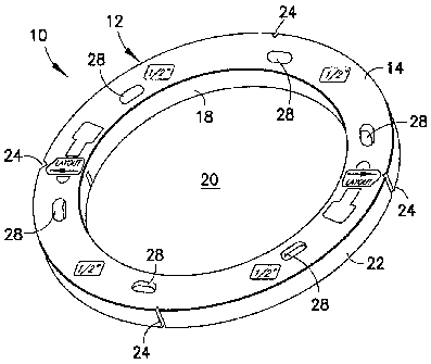
Summary of the Invention
With reference to the figures, a spacer 10 is provided for supporting a closet
flange above a sub-flooring. The spacer 10 includes a body 12, which is
preferably disc-shaped. The body 12 includes opposed first and second faces 14
and 16, which are both preferably flat. In addition, the body 12 includes an
inner
edge 18, defining an opening 20 through the body 12, and an outer edge 22.
Preferably, the body 10 has an annular shape with the inner and/or outer edges
18, 22 being circular. The outer edge 22 is preferably smooth, without any
protrusions extending therefrom, and arcuate.
As shown in the figures, it is preferred that the body 12 be unitary. The
body 12 may be formed from any material, preferably, a polymeric material. The
body 12 may be formed from plastic, which is well-suited to be molded (e.g.,
injection molded). The body 12 may also be colored (e.g., uniformly colored).
For example, the body 12 may be colored white or red. With coloring, the body
12 may be made visually easy to spot. Also, the body 12 may be colored to be
4
CA 02831942 2013-10-31
readily distinguished from other building materials, particularly piping.
Where
standard polyvinyl chloride (PVC) piping, which is white, is being used, the
body
12 may be colored red, and where standard acrylonitrile butadiene styrene
(ABS)
piping, which is black, is being used, the body 12 may be made white and/or
red.
Specifically, and with reference to Figure 4, it is preferred that the first
and second faces 14 and 16 be generally parallel. The body 12 may be formed
with a generally constant thickness T between the first and second faces 14
and
16. The thickness T may be generally .125 inches, .25 inches, .5 inches, or
.75
inches.
The spacer 10 may be optionally provided with additional features. As
shown in Figure 2, at least one notch 24, preferably at least two of the
notches 24,
are provided in the outer edge 22. The notches 24, as discussed below, are
usable
to measure and locate the proper location of the spacer 10 at an installation.
It is
preferred that two of the notches 24 be located along a straight axis
intersecting a
center of the body 12 (e.g., a line coinciding with a diameter of the body
12). For
convenience, and as shown in the figures, four of the notches 24 may be
provided, with the notches 24 forming two pairs, each pair being disposed
along a
straight axis intersecting a center of the body 12. The two defined axes are
preferably generally perpendicular (e.g., the four notches are located
substantially
90 apart along the outer edge 24).
The spacer 10 may also be provided with at least one score line 26 which
defines a reduced-thickness portion in the body 12 between the first and
second
faces 14 and 16 (Figure 4). It is preferred that at least two of the score
lines 26 be
provided and aligned to coincide along a straight axis intersecting a center
of the
body 12. With this arrangement, the score lines 26 provide a line of weakness
in
5
CA 02831942 2013-10-31
the body 12 which can be broken resulting in the spacer 10 being broken into
two
generally-equal parts. As described below, the breaking of the spacer 10 into
two
parts may aide in its installation. To enhance the weakness of the score lines
26,
the notches 24 may be aligned with the score lines 26, as best shown in Figure
4.
One or more fastener holes 28 may be formed in the body 12 to extend
through and between the first and second faces 14 and 16. Preferably, six of
the
fastener holes 28 are provided, with three of the fastener holes 28 being
located
on each side of the score lines 26. The fastener holes 28 are
circumferentially
spaced apart and preferably are elongated slots to allow for radial adjustment
of
the body 12 relative to any fastener(s) passing therethrough. The fastener
holes
28 are sized to accommodate typical fastener diameters, e.g., typical screw
diameters.
With reference to Figures 5(a)-(d) and 6, an illustrative method of
installing the spacer 10 is depicted. The spacer 10 is used to support a
closet
flange 30 which includes a pipe section 32 and an annular flange 34 extending
radially outwardly from the pipe section 32.
Prior to installation of finished flooring, and after preparation of a sub-
flooring 36, a hole 38 is required to allow for passage of the pipe section 32
through the sub-flooring 36. As is well known in the art, the closet flange
30, and
thus the hole 38, must be located a predetermined distance from a wall to
allow
for proper toilet installation. With reference to Figure 5(a), the hole 38
preferably
is layed out by locating at least one of the notches 24 a predetermined
distance
from a relevant wall W. To ensure proper location, it is preferred that two of
the
notches 24 (which are located along an axis intersecting a center of the body
12)
be located the predetermined distance from the wall W. With two of the notches
6
CA 02831942 2013-10-31
24 being located the predetermined distance from the wall W, the notches 24
define an axis generally parallel to the wall W at the predetermined distance.
Once the predetermined distance is set, and as shown in Figure 5(b), the inner
edge 18 of the spacer 10 is traced by a writing or marking instrument Ito
provide
an outline for the hole 38. The spacer 10 is removed and the hole 38 is formed
by
cutting through the sub-flooring 36 along the outline.
The spacer 10 is then placed on the sub-flooring 36 with the opening 20
generally coinciding with the hole 38, as shown in Figure 5(c). It is desired
that
both the opening 20 and the hole 38 be sized to permit passage therethrough of
the pipe section 32 of the closet flange 30 but not permit passage of the
annular
flange 34.
Depending on the thickness of the finished flooring, one or more of the
spacers 10 can be stacked about the hole 38. By using multiple spacers 10,
particularly of varying thicknesses T, stacks of various thicknesses can be
achieved.
Once the spacer(s) 10 have been set about the hole 38, the pipe section 32
of the closet flange 30 is inserted through the opening 20 and through the
hole 38
(Figure 5(d)) until the annular flange 34 comes to rest on top of the
spacer(s) 10
(Figure 6). It is preferred that the body 12 be sized slightly larger than the
diameter of the annular flange 34 to ensure a full resting surface is
provided. It is
further preferred that the outer edge 22 protrude radially .125 inches beyond
the
annular flange 34 on all sides.
The entire spacer(s) 10/closet flange 30 assembly is then fastened to sub-
flooring 36 using fasteners 40. The fasteners 40 preferably pass through the
annular flange 34, the body 12, and into the sub-flooring 36. Any known
7
CA 02831942 2013-10-31
fasteners 40 may be used (e.g., screws, nails, rivets, etc.) and the fasteners
40
may be passed through the fastener holes 28 to limit stresses on the body 12.
Once fastened, a finished flooring 42 may be installed about the spacer(s)
10/closet flange 30, as shown in Figure 6. The finished flooring 42 may be of
any known materials, including tiles, boards, poured concrete, and so forth.
Where the finished flooring 42 is being poured, the spacer(s) 10
advantageously
seal the hole 38 from the poured material.
It is preferred that the thickness of the spacer(s) 10 generally equal the
height H of the finished flooring 42. In this manner, lower face 44 of the
closet
flange 30 will be generally flush with the top of the finished flooring 42. As
shown in Figure 7, closet flange bolts C may be attached to the closet flange
30
as known in the art. The closet flange bolts C rest on the uppermost spacer
10.
With this arrangement, a toilet may rest flush on the finished flooring 42 and
be
directly connected to the closet flange 30 without extenders or other devices.
It is preferred that the thickness T of the spacer 10 generally equal the
height H of the finished flooring 40. In this manner, only one of the spacers
10 is
required. To allow for mixing and matching of various thicknesses, two or more
of the spacers 10 having different thicknesses T may be used as shown in
Figure
7. Advantageously, two or more of the spacers 10, having different thicknesses
T, can be sold as a kit to accommodate different heights H of the finished
flooring 42. The stacked spacers 10 may be rotated freely relative to each
other,
particularly where the spacers 10 have interengaging flat first and/or second
faces
14, 16. For example, the fastener holes 28 of the stacked spacers 10 may be
aligned by rotating the stacked spacers 10.
8
CA 02831942 2013-10-31
-
= Installation of the spacer 10 may be aided by breaking the spacer 10
along
the score lines 26. For example, with the spacer 10 being broken apart, the
spacer 10 may be placed about a pre-installed closet flange 30. As shown in
Figure 8, a first part 46 of the spacer 10 is inserted between the annular
flange 34
and the sub-flooring 36, to be followed by a second part of the spacer 10 (not
shown). As indicated above, it is preferred that the spacer 10 break into two
generally equal parts, but it may be broken into any number of parts which
permit
it to function properly. The parts 46 of the spacer 10 are then fastened as
described above.
9