Note : Les descriptions sont présentées dans la langue officielle dans laquelle elles ont été soumises.
Sliding Door
CROSS REFERENCE TO RELATED APPLICATIONS
Applicant claims priority from U.S. Provisional Pat. App. No. 61/472,738 filed
on April 7,
2011 and U.S. Non-provisional Pat. App. No. 13/420,319, filed on March 14,
2012,
published as U.S. Pat. App. Publication No. 2012/0255230A1 on October 11,2012.
FIELD OF THE INVENTION
The present invention relates to a trackless sliding door with a break-away
function.
STATEMENT REGARDING FEDERALLY SPONSORED RESEARCH OR
DEVELOPMENT
No federal funds were used to create or develop the invention herein.
REFERENCE TO SEQUENCE LISTING, A TABLE, OR A COMPUTER PROGRAM
LISTING COMPACT DISK APPENDIX
N/A
1
CA 2832599 2018-08-16
CA 02832599 2013-10-07
WO 2012/139115 PCT/US2012/032766
BACKGROUND OF THE INVENTION
Manual sliding doors with a break-away function are commonly used as entrances
for
Intensive Care (ICU) suites in hospitals and health care facilities. Doors of
this type provide
unobstructed vision of the patient for the care providers as well as privacy
and sound
reduction for the patient. While conventional models of manual sliding doors
for this purpose
provide a clear view of patients and privacy they have inherent problems.
Manual sliding doors of the subject type are available in two basic
arrangements: (i) trackless
sliding doors and (ii) tracked sliding doors. A trackless ICU-type manual
sliding door of the
subject type generally includes a header member having a top side, back side
and bottom side
along with an access service cover. The access service cover may be configured
as either a
removable cover or a hinged cover that is capable of being supported in both
the open and
closed positions. Also present within the header member is a top track for
sliding door
support rollers and stop blocks to prevent the sliding panels from sliding
past the allowable or
necessary distance. The door unit also includes one or more sliding panels and
one or more
fixed panels.
The sliding door panel and fixed panel will have the ability to break away in
either the event
of an emergency and the need to move equipment into the ICU suite. The sliding
panel(s) are
often outfitted with a type of torsion bar that will support the panel in the
event of break
away. The conventional construction of these types of doors is extruded
aluminum members
for the header and door stiles.
Conventional trackless manual sliding doors will not break away in any
position. Instead, the
sliding panel first must be slid fully open and then a release lever operated
on the fixed panel.
Once the sliding panel is fully open and the lever released, both doors may be
swung out
together as a unit. This action requires previous or special knowledge for
proper performance.
In an emergency situation, an operator may forget the sequence needed. Also,
an individual
with no knowledge of the door could not be expected to perform such an
operation.
Furthermore, the presence of the release lever, commonly known as a flush
bolt, presents a
maintenance and service issue. If the flush bolt is not fully released when
the operator
attempts to break away the panels, the guide bracket for the slide bolt
portion of the flush bolt
can easily be broken or misaligned. It is then possible when the guide is
damaged or broken,
that the fixed panel cannot be readily secured back into operating position.
The lack of a
2
a breakaway feature that operates at any time during operation without special
knowledge
presents a problem in regards to life safety and egress.
Conventional tracked units, while able to break away in any position during
the sliding
panel's travel, require a floor mounted track. The presence of a track on the
floor presents an
obstacle that needs to be overcome when moving large equipment into an ICU
suite.
Furthermore the conventional floor track provides a recess for the sliding
panel bottom guide
pin. This recess is difficult to keep clean and clear of debris. In an
environment such as an
ICU wing, infectious control is a major concern. The floor track could harbor
dirt, bacteria,
and/or pathogens making it more difficult to maintain a clean working
environment.
Accordingly, the sliding doors as found in the prior art present several
problems.
SUMMARY OF THE INVENTION
In accordance with an aspect of the present invention, there is provided a
sliding door
comprising: a. a header having first and second ends, wherein said header is
secured to a top
portion of an opening, wherein said header is includes a sliding track along
the length thereof,
and wherein said header includes a fixed panel guide; b. a fixed panel
pivotally engaged with
said header first end; and, c. a sliding panel cooperatively engaged with said
header adjacent
a sliding panel top rail such that said sliding panel may move linearly from
said header first
end to said header second end, wherein a sliding panel bottom rail is
cooperatively engaged
with a fixed panel bottom rail; and wherein said sliding panel may pivot with
respect to said
header and said fixed panel at any position between said header first and
second ends.
In accordance with another aspect of the present invention, there is provided
a sliding door
comprising: a. a header having first and second ends, wherein said header is
secured to a top
portion of an opening, wherein said header includes a sliding track along the
length thereof,
wherein said header includes a fixed panel guide along a portion thereof; b. a
floor plate
secured to a flooring surface below said header adjacent said header first
end; c. a fixed panel
pivotally engaged with said header first end; d. a first lock member engaged
with a top fixed
panel top rail, wherein said first lock member selectively engages said fixed
panel guide such
that in a first position said fixed panel is secured in an orientation
parallel with respect to
3
CA 2832599 2018-08-16
said header, and such that in a second position said fixed panel may pivot
with respect to said
header and said floor plate; e. a sliding panel cooperatively engaged with
said header adjacent
a sliding panel top rail such that said sliding panel may move linearly from
said header first
end to said header second end, wherein a sliding panel bottom rail is
cooperatively engaged
with a fixed panel bottom rail, and wherein said sliding panel may pivot with
respect to said
header and said fixed panel at any position between said header first and
second ends; and f. a
second lock member engaged with a top sliding panel top rail, wherein said
lock member
selectively engages said header such that in a first position said sliding
panel occupies a plane
parallel to but offset from said fixed panel, and such that in a second
position said sliding
panel may pivot with respect to said header and said fixed panel.
In accordance with another aspect of the present invention, there is provided
a sliding door
comprising: a. a header secured to a top portion of an opening, said header
comprising: i. a
first and a second end; ii. a sliding track extending along the length of said
header; iii. a fixed
panel guide extending along a portion of said header adjacent said header
first end; iv. a fixed
panel pivot pin extending downward from said header adjacent said header first
end; b. a
floor plate secured to a flooring surface below said header adjacent said
header first end,
wherein said floor plate includes a fixed panel post extending upward from
said flooring
surface, and wherein the longitudinal axis of said fixed panel post is the
same as that of said
fixed panel pivot pin; c. a carrier bar slideably engaged with said sliding
track, said carrier
bar comprising: i. a first and a second end; ii. a sliding panel pivot pin
extending downward
from said carrier bar adjacent said carrier bar first end; d. a fixed panel
pivotally engaged
with said fixed panel pivot pin and said fixed panel post, said fixed panel
comprising: i. a
fixed panel first vertical rail having first and second ends, wherein said
fixed panel first end is
positioned adjacent said header first end; ii. a fixed panel top rail having
first and second
ends, wherein said fixed panel top rail first end is engaged with said fixed
panel first vertical
rail first end; iii. a fixed panel bottom rail having first and second ends,
wherein said fixed
panel bottom rail first end is positioned adjacent said floor plate, and
wherein a guide track
extends from said fixed panel first end to said fixed panel second end; e. a
first lock member
selectively engageable with said fixed panel top rail and said fixed panel
guide, wherein said
first lock member selectively engages said fixed panel guide such that in a
first position said
fixed panel is secured in an orientation parallel to said header, and such
that in a second
position said fixed panel may pivot about said fixed panel pivot pin and said
fixed panel post;
f. a sliding panel pivotally engaged with said carrier bar and said fixed
panel, wherein said
3a
CA 2832599 2018-08-16
sliding panel may move with said carrier bar along the length of said sliding
track, said
sliding panel comprising: i. a sliding panel first vertical rail having first
and second ends,
wherein said sliding panel first vertical rail first end is positioned
adjacent said first end of
said carrier bar; ii. a sliding panel top rail having first and second ends,
wherein said sliding
panel top rail first end is engaged with said sliding panel first vertical
rail first end; iii. a
sliding panel bottom rail having first and second ends, wherein said sliding
panel bottom rail
first end is positioned adjacent said floor plate when said carrier bar is
positioned adjacent
said header first end, and wherein said sliding panel slidably engages said
guide track; g. a
second lock member selectively engageable with said top sliding panel top rail
and said
carrier bar, wherein said second lock member selectively engages said carrier
bar such that in
a first position said sliding panel occupies a plane parallel to but offset
from said fixed panel,
and such that in a second position said sliding panel may pivot with respect
to said carrier bar
and said fixed panel.
In accordance with another aspect of the present invention, there is provided
a method for
providing selective access through an outer frame of a sliding door without
the use of any
floor track, said method comprising the steps: a. outfitting said outer frame
with a header
adjacent the top portion of said outer frame, wherein said header include
first and second
ends, wherein said header is substantially linear and is formed with a sliding
track and fixed
panel guide therein; b. securing a floor plate to a floor surface below said
first end of said
header; c. pivotally engaging a fixed panel with said fixed panel guide and
said floor plate; d.
providing a lock member between said outer frame and said fixed panel such
that said fixed
panel may be selectively secured in a first position with respect to said
outer frame, wherein
said fixed panel is substantially parallel with said header in said first
position; e.
cooperatively engaging a sliding panel adjacent a sliding panel top rail with
said header such
that said sliding panel may move linearly along the length of said header; f.
cooperatively
engaging said sliding panel adjacent a sliding panel bottom rail with said
fixed panel to
ensure that said sliding panel is straight and plumb with respect to said
outer frame and said
fixed panel when said sliding panel is moving along the length of said header,
wherein said
sliding panel is pivotal with respect to said header and said fixed panel; g.
providing a lock
member between said header and said sliding panel such that said sliding panel
may be
selectively secured between said first and second ends of said header in a
plane that is parallel
to but offset from said fixed panel when said fixed panel is in said first
position; h.
determining an amount of force that when applied to said sliding panel in a
direction
3b
CA 2832599 2018-08-16
perpendicular to said header that will overcome said lock member between said
sliding panel
and said header that will cause said sliding panel to pivot with respect to
said header
regardless of the position of said sliding panel along the length of said
header; and, i.
determining an amount of force that when applied to said fixed panel in a
direction
perpendicular to said header that will overcome said lock member between said
fixed panel
and said outer frame that will cause said fixed panel to pivot with respect to
said header when
said sliding panel is positioned adjacent said header first end.
In accordance with another aspect of the present invention, there is provided
a sliding door
comprising: a. a header having first and second ends, wherein said header is
secured to a top
portion of an opening, wherein said header includes a sliding track along the
length thereof,
wherein said header includes a fixed panel guide along a portion thereof, and
wherein said
fixed panel guide is formed with a guide interlock extending therefrom; b. a
floor plate
secured to a flooring surface below said header adjacent said header first
end; c. a fixed panel
pivotally engaged with said header first end, wherein a fixed panel top rail
is formed with a
fixed panel interlock extending therefrom, and wherein said guide interlock
and said fixed
panel interlock cooperatively engage one another when said fixed panel is in a
fixed panel
first position; d. a first lock member engaged with a top fixed panel top
rail, wherein said first
lock member selectively engages said fixed panel guide such that in said fixed
panel first
position said fixed panel is secured in an orientation parallel with respect
to said header, and
such that in a fixed panel second position said fixed panel may pivot with
respect to said
header and said floor plate; e. a sliding panel cooperatively engaged with
said header adjacent
a sliding panel top rail such that said sliding panel may move linearly from
said header first
end to said header second end, wherein a sliding panel bottom rail is
cooperatively engaged
with a fixed panel bottom rail, and wherein said sliding panel may pivot with
respect to said
header and said fixed panel at any position between said header first and
second ends; f. a
carrier bar having a portion thereof slidably mounted within said sliding
track, wherein said
carrier bar includes a sliding panel pivot pin that pivotally engages said
sliding panel top rail;
and, g. a second lock member engaged with a top sliding panel top rail,
wherein said lock
member selectively engages said header such that in a sliding panel first
position said sliding
panel occupies a plane parallel to but offset from said fixed panel, and such
that in a sliding
panel second position said sliding panel may pivot with respect to said header
and said fixed
panel.
3c
CA 2832599 2018-08-16
In accordance with another aspect of the present invention, there is provided
a sliding door
comprising: a. a header having first and second ends, wherein said header is
secured to a top
portion of an opening, wherein said header includes a sliding track along the
length thereof,
wherein said header includes a fixed panel guide along a portion thereof, and
wherein said
fixed panel guide is formed with a guide interlock extending therefrom; b. a
floor plate
secured to a flooring surface below said header first end; c. a fixed panel
pivotally engaged
with said header first end, wherein a fixed panel top rail is formed with a
fixed panel
interlock extending therefrom, and wherein said guide interlock and said fixed
panel interlock
cooperatively engage one another when said fixed panel is in a fixed panel
first position; d. a
first lock member engaged with said fixed panel top rail, wherein said first
lock member
selectively engages said fixed panel guide such that in said fixed panel first
position said
fixed panel is secured in an orientation parallel with respect to said header,
and such that in a
fixed panel second position said fixed panel may pivot with respect to said
header and said
floor plate, and wherein said first lock member further comprises a guide
detent formed in
said fixed panel guide and a corresponding spring loaded ball placed in said
fixed panel top
rail; e. a sliding panel cooperatively engaged with said header adjacent a
sliding panel top rail
such that said sliding panel may move linearly from said header first end to
said header
second end, wherein a sliding panel bottom rail is cooperatively engaged with
a fixed panel
bottom rail, and wherein said sliding panel may pivot with respect to said
header and said
fixed panel at any position between said header first and second ends; f. a
carrier bar having a
portion thereof slidably mounted within said sliding track, and wherein said
carrier bar
includes a sliding panel pivot pin that pivotally engages said sliding panel
top rail; and, g. a
second lock member engaged with a sliding panel top rail, wherein said lock
member
selectively engages said header such that in a sliding panel first position
said sliding panel
occupies a plane parallel to but offset from said fixed panel, and such that
in a sliding panel
second position said sliding panel may pivot with respect to said header and
said fixed panel,
wherein said second lock member further comprises a carrier bar detent formed
in said carrier
bar and a corresponding spring loaded ball placed in said sliding panel top
rail, and wherein
the periphery of said panel bearing is positioned to engage said sliding panel
when both said
fixed and sliding panel are in said second positions, respectively.
In accordance with another aspect of the present invention, there is provided
a method for
providing selective access through an outer frame of a sliding door without
the use of any
floor track, said method comprising the steps: a. outfitting said outer frame
with a header
3d
CA 2832599 2018-08-16
adjacent the top portion of said outer frame, wherein said header include
first and second
ends, wherein said header is substantially linear and is formed with a sliding
track and fixed
panel guide therein; b. securing a floor plate to a floor surface below said
first end of said
header; c. pivotally engaging a fixed panel with said fixed panel guide and
said floor plate; d.
providing a lock member between said outer frame and said fixed panel such
that said fixed
panel may be selectively secured in a first position with respect to said
outer frame, wherein
said fixed panel is substantially parallel with said header in said first
position; e.
cooperatively engaging a sliding panel adjacent a sliding panel top rail with
said header such
that said sliding panel may move linearly along the length of said header; f.
cooperatively
engaging said sliding panel adjacent a sliding panel bottom rail with said
fixed panel to
ensure that said sliding panel is straight and plumb with respect to said
outer frame and said
fixed panel when said sliding panel is moving along the length of said header,
wherein said
sliding panel is pivotal with respect to said header and said fixed panel; g.
providing a lock
member between said header and said sliding panel such that said sliding panel
may be
selectively secured between said first and second ends of said header in a
plane that is parallel
to but offset from said fixed panel when said fixed panel is in said first
position; h.
determining an amount of force that when applied to said sliding panel in a
direction
perpendicular to said header that will overcome said lock member between said
sliding panel
and said header that will cause said sliding panel to pivot with respect to
said header
regardless of the position of said sliding panel along the length of said
header; and, i.
determining an amount of force that when applied to said fixed panel in a
direction
perpendicular to said header that will overcome said lock member between said
fixed panel
and said outer frame that will cause said fixed panel to pivot with respect to
said header when
said sliding panel is positioned adjacent said header first end.
In accordance with another aspect of the present invention, there is provided
a method for
providing selective access through an outer frame of a sliding door without
the use of any
floor track, said method comprising the steps: a. outfitting said outer frame
with a header
adjacent the top portion of said outer frame, wherein said header include
first and second
ends, wherein said header is substantially linear and is formed with a sliding
track and fixed
panel guide therein; b. securing a floor plate to a floor surface below said
first end of said
header; c. pivotally engaging a fixed panel with said fixed panel guide and
said floor plate; d.
providing a lock member between said outer frame and said fixed panel such
that said fixed
panel may be selectively secured in a first position with respect to said
outer frame, wherein
3e
CA 2832599 2018-08-16
said fixed panel is substantially parallel with said header in said first
position; e.
cooperatively engaging a sliding panel adjacent a sliding panel top rail with
said header such
that said sliding panel may move linearly along the length of said header; f.
cooperatively
engaging said sliding panel adjacent a sliding panel bottom rail with said
fixed panel to
ensure that said sliding panel is straight and plumb with respect to said
outer frame and said
fixed panel when said sliding panel is moving along the length of said header,
wherein said
sliding panel is pivotal with respect to said header and said fixed panel; g.
providing a lock
member between said header and said sliding panel such that said sliding panel
may be
selectively secured between said first and second ends of said header in a
plane that is parallel
to but offset from said fixed panel when said fixed panel is in said first
position; h. applying
an appropriate force to said sliding panel in a direction perpendicular to
said header to
overcome said lock member positioned between said sliding panel and said
header to cause
said sliding panel to pivot with respect to said header; and, i. applying an
appropriate force to
said fixed panel in a direction perpendicular to said header to overcome said
lock member
positioned between said fixed panel and said outer frame that will cause said
fixed panel to
pivot with respect to said header when said sliding panel is positioned
adjacent said header
first end.
In accordance with another aspect of the present invention, there is provided
a sliding door
comprising: a. a header having first and second ends, wherein said header is
secured to a top
portion of an opening, wherein said header includes a sliding track along the
length thereof,
wherein said header includes a fixed panel guide along a portion thereof, and
wherein said
fixed panel guide is formed with a guide interlock extending therefrom; b. a
floor plate
secured to a flooring surface below said header first end, wherein said floor
plate further
comprises a fixed panel post pivotally engaged with said fixed panel, and
wherein said floor
plate further comprises a panel bearing; c. a fixed panel pivotally engaged
with said header
first end, wherein a fixed panel top rail is formed with a fixed panel
interlock extending
therefrom, and wherein said guide interlock and said fixed panel interlock
cooperatively
engage one another when said fixed panel is in a fixed panel first position;
d. a first lock
member engaged with said fixed panel top rail, wherein said first lock member
selectively
engages said fixed panel guide such that in said fixed panel first position
said fixed panel is
secured in an orientation parallel with respect to said header, and such that
in a fixed panel
second position said fixed panel may pivot with respect to said header and
said floor plate,
and wherein said first lock member further comprises a guide detent formed in
said fixed
3f
CA 2832599 2018-08-16
panel guide and a corresponding spring loaded ball placed in said fixed panel
top rail; e. a
sliding panel cooperatively engaged with said header adjacent a sliding panel
top rail such
that said sliding panel may move linearly from said header first end to said
header second
end, wherein a sliding panel bottom rail is cooperatively engaged with a fixed
panel bottom
rail, and wherein said sliding panel may pivot with respect to said header and
said fixed panel
at any position between said header first and second ends; f. a carrier bar
having a portion
thereof slidably mounted within said sliding track, and wherein said carrier
bar includes a
sliding panel pivot pin that pivotally engages said sliding panel top rail;
and g. a second lock
member engaged with a sliding panel top rail, wherein said lock member
selectively engages
said header such that in a sliding panel first position said sliding panel
occupies a plane
parallel to but offset from said fixed panel, and such that in a sliding panel
second position
said sliding panel may pivot with respect to said header and said fixed panel,
wherein said
second lock member further comprises a carrier bar detent formed in said
carrier bar and a
corresponding spring loaded ball placed in said sliding panel top rail, and
wherein the
periphery of said panel bearing is positioned to engage said sliding panel
when both said
fixed and sliding panel are in said second positions, respectively.
In accordance with an aspect of the present invention, there is provided a
sliding door
comprising: a. a header secured to a top portion of an opening, said header
comprising: i. a
first and a second end; ii. a sliding track extending along the length of said
header; iii. a fixed
panel guide extending along a portion of said header adjacent said header
first end, wherein
said fixed panel guide further comprises a guide interlock extending
therefrom; iv. a fixed
panel pivot pin extending downward from said header adjacent said header first
end; b. a
floor plate secured to a flooring surface below said header first end, wherein
said floor plate
includes a fixed panel post extending upward from said flooring surface,
wherein said floor
plate further comprises a panel bearing, and wherein a longitudinal axis of
said fixed panel
post is the same as that of said fixed panel pivot pin; c. a carrier bar
slideably engaged with
said sliding track, said carrier bar comprising: i. a first and a second end;
ii. a sliding panel
pivot pin extending downward from said carrier bar adjacent said carrier bar
first end; iii. a
carrier bar interlock extending therefrom; d. a fixed panel pivotally engaged
with said fixed
panel pivot pin and said fixed panel post, said fixed panel comprising: i. a
fixed panel first
vertical rail having first and second ends, wherein said fixed panel first end
is positioned
adjacent said header first end; ii. a fixed panel top rail having first and
second ends, wherein
said fixed panel top rail first end is engaged with said fixed panel first
vertical rail first end
3g
CA 2832599 2018-08-16
wherein said fixed panel top rail further comprises a fixed panel interlock
extending
therefrom; iii. a fixed panel bottom rail having first and second ends,
wherein said fixed panel
bottom rail first end is positioned adjacent said floor plate, and wherein a
guide track extends
from said fixed panel first end to said fixed panel second end; e. a first
lock member
selectively engageable with said fixed panel top rail and said fixed panel
guide, wherein said
first lock member selectively engages said fixed panel guide such that in a
fixed panel first
position said fixed panel is secured in an orientation parallel to said
header, and such that in a
fixed panel second position said fixed panel may pivot about said fixed panel
pivot pin and
said fixed panel post, and wherein said guide interlock and said fixed panel
interlock
cooperatively engage one another in said fixed panel first position; f. a
sliding panel pivotally
engaged with said carrier bar and said fixed panel, wherein said sliding panel
may move with
said carrier bar along the length of said sliding track, said sliding panel
comprising: i. a
sliding panel first vertical rail having first and second ends, wherein said
sliding panel first
vertical rail first end is positioned adjacent said first end of said carrier
bar; ii. a sliding panel
top rail having first and second ends, wherein said sliding panel top rail
first end is engaged
with said sliding panel first vertical rail first end; iii. a sliding panel
bottom rail having first
and second ends, wherein said sliding panel bottom rail first end is
positioned adjacent said
floor plate when said carrier bar is positioned adjacent said header first
end, and wherein said
sliding panel slidably engages said guide track; g. a second lock member
selectively
engageable with said top sliding panel top rail and said carrier bar, wherein
said second lock
member selectively engages said carrier bar such that in a first position said
sliding panel
occupies a plane parallel to but offset from said fixed panel, and such that
in a second
position said sliding panel may pivot with respect to said carrier bar and
said fixed panel,
wherein the periphery of said panel bearing is positioned to engage said
sliding panel when
both said fixed and sliding panel are in said second positions, respectively.
In accordance with an aspect of the present invention, there is provided a
method for
providing selective access through an outer frame of the sliding door as
described above
without the use of any floor track, said method comprising the steps: a.
outfitting said outer
frame with a header adjacent the top portion of said outer frame, wherein said
header include
first and second ends, wherein said header is substantially linear and is
formed with a sliding
track and fixed panel guide therein; b. securing a floor plate to a floor
surface below said first
end of said header; c. pivotally engaging a fixed panel with said fixed panel
guide and said
floor plate; d. providing a lock member between said outer frame and said
fixed panel such
3h
CA 2832599 2018-08-16
that said fixed panel may be selectively secured in a first position with
respect to said outer
frame, wherein said fixed panel is substantially parallel with said header in
said first position;
e. cooperatively engaging a sliding panel adjacent a sliding panel top rail
with said header
such that said sliding panel may move linearly along the length of said
header; f
cooperatively engaging said sliding panel adjacent a sliding panel bottom rail
with said fixed
panel to ensure that said sliding panel is straight and plumb with respect to
said outer frame
and said fixed panel when said sliding panel is moving along the length of
said header,
wherein said sliding panel is pivotal with respect to said header and said
fixed panel; g.
providing a lock member between said header and said sliding panel such that
said sliding
panel may be selectively secured between said first and second ends of said
header in a plane
that is parallel to but offset from said fixed panel when said fixed panel is
in said first
position; h. determining an amount of force that when applied to said sliding
panel in a
direction perpendicular to said header that will overcome said lock member
between said
sliding panel and said header that will cause said sliding panel to pivot with
respect to said
header regardless of the position of said sliding panel along the length of
said header; and, i.
determining an amount of force that when applied to said fixed panel in a
direction
perpendicular to said header that will overcome said lock member between said
fixed panel
and said outer frame that will cause said fixed panel to pivot with respect to
said header when
said sliding panel is positioned adjacent said header first end.
In accordance with an aspect of the present invention, there is provided a
method for
providing selective access through an outer frame of a sliding door without
the use of any
floor track, said method comprising the steps: a. outfitting said outer frame
with a header
adjacent a top portion of said outer frame, wherein said header includes first
and second ends,
wherein said header is substantially linear and is formed with a sliding track
and fixed panel
guide therein; b. securing a floor plate to a floor surface below said first
end of said header; c,
pivotally engaging a fixed panel with said fixed panel guide and said floor
plate; d. providing
a lock member between said outer frame and said fixed panel such that said
fixed panel may
be selectively secured in a first position with respect to said outer frame,
wherein said fixed
panel is substantially parallel with said header in said first position; e.
pivotally engaging a
sliding panel with a carrier bar, wherein said carrier bar is engaged with
said header such that
said carrier bar and sliding panel may move linearly along the length of said
header; f.
pivotally engaging said sliding panel with said fixed panel to ensure that
said sliding panel is
straight and plumb with respect to said outer frame and said fixed panel when
said sliding
3i
CA 2832599 2018-08-16
panel is moving along the length of said header; g. providing a lock member
between said
carrier bar and said sliding panel such that said sliding panel may be
selectively secured
between said first and second ends of said header in a plane that is parallel
to but offset from
said fixed panel when said fixed panel is in said first position; h. adjusting
said lock member
such that a specific amount of force applied to said sliding panel in a
direction perpendicular
to said header will overcome said lock member between said sliding panel and
said carrier
bar causing said sliding panel to pivot with respect to said header regardless
of the position of
said sliding panel along the length of said header; and, i. adjusting said
lock member such
that a specific amount of force applied to said fixed panel in a direction
perpendicular to said
header will overcome said lock member between said fixed panel and said outer
frame
causing said fixed panel to pivot with respect to said header when said
sliding panel is
positioned adjacent said header first end.
In accordance with another aspect of the present invention, there is provided
a method for
providing selective access through an outer frame of a sliding door without
the use of any
floor track, said method comprising the steps: a. outfitting said outer frame
with a header
adjacent a top portion of said outer frame, wherein said header includes first
and second ends,
wherein said header is substantially linear and is formed with a sliding track
and fixed panel
guide therein; b. securing a floor plate to a floor surface below said first
end of said header; c.
pivotally engaging a fixed panel with said fixed panel guide and said floor
plate; d. providing
a lock member between said outer frame and said fixed panel such that said
fixed panel may
be selectively secured in a first position with respect to said outer frame,
wherein said fixed
panel is substantially parallel with said header in said first position; e.
pivotally engaging a
sliding panel with a carrier bar, wherein said carrier bar is engaged with
said header such that
said carrier bar and said sliding panel may move linearly along the length of
said header; f.
pivotally engaging said sliding panel with said fixed panel to ensure that
said sliding panel is
straight and plumb with respect to said outer frame and said fixed panel when
said sliding
panel is moving along the length of said header; g. providing a lock member
between said
carrier bar and said sliding panel such that said sliding panel may be
selectively secured
between said first and second ends of said header in a plane that is parallel
to but offset from
said fixed panel when said fixed panel is in said first position; h. applying
an appropriate
force to said sliding panel in a direction perpendicular to said header to
overcome said lock
member positioned between said sliding panel and said header to cause said
sliding panel to
pivot with respect to said header when said sliding and is at any position
between said first
3j
CA 2832599 2018-08-16
and second ends of said header; and, i. applying an appropriate force to said
fixed panel in a
direction perpendicular to said header to overcome said lock member positioned
between said
fixed panel and said outer frame that will cause said fixed panel to pivot
with respect to said
header when said sliding panel is positioned adjacent said header first end.
In accordance with another aspect of the present invention, there is provided
a sliding door
comprising: a. a header having first and second ends, wherein said header is
secured to a top
portion of an opening, wherein said header includes a sliding track along the
length thereof,
wherein said header includes a fixed panel guide along a portion thereof, and
wherein said
fixed panel guide is formed with a guide interlock extending therefrom; b. a
floor plate
secured to a flooring surface below said header first end, wherein said floor
plate further
comprises a fixed panel post pivotally engaged with said fixed panel, and
wherein said floor
plate further comprises a panel bearing; c. a fixed panel pivotally engaged
with said header
first end, wherein a fixed panel top rail is formed with a fixed panel
interlock extending
therefrom, and wherein said guide interlock and said fixed panel interlock
cooperatively
engage one another when said fixed panel is in a fixed panel first position;
d. a first lock
member engaged with said fixed panel top rail, wherein said first lock member
selectively
engages said fixed panel guide such that in said fixed panel first position
said fixed panel is
secured in an orientation parallel with respect to said header, and such that
in a fixed panel
second position said fixed panel may pivot with respect to said header and
said floor plate,
and wherein said first lock member further comprises a guide detent formed in
said fixed
panel guide and a corresponding spring loaded ball placed in said fixed panel
top rail; e. a
sliding panel cooperatively engaged with said header adjacent a sliding panel
top rail such
that said sliding panel may move linearly from said header first end to said
header second
end, wherein a sliding panel bottom rail is cooperatively engaged with a fixed
panel bottom
rail, and wherein said sliding panel may pivot with respect to said header and
said fixed panel
at any position between said header first and second ends; f. a carrier bar
having a portion
thereof slidably mounted within said sliding track, and wherein said carrier
bar includes a
sliding panel pivot pin that pivotally engages said sliding panel top rail;
and g. a second lock
member engaged with a sliding panel top rail, wherein said lock member
selectively engages
said header such that in a sliding panel first position said sliding panel
occupies a plane
parallel to but offset from said fixed panel, and such that in a sliding panel
second position
said sliding panel may pivot with respect to said header and said fixed panel,
wherein said
second lock member further comprises a carrier bar detent formed in said
carrier bar and a
3k
CA 2832599 2018-08-16
corresponding spring loaded ball placed in said sliding panel top rail, and
wherein the
periphery of said panel bearing is positioned to engage said sliding panel
when both said
fixed and sliding panel are in said second positions, respectively.
In accordance with another aspect of the present invention, there is provided
a sliding door
comprising: a. a header secured to a top portion of an opening, said header
comprising: i. a
first and a second end; ii. a sliding track extending along the length of said
header; iii. a fixed
panel guide extending along a portion of said header adjacent said header
first end, wherein
said fixed panel guide further comprises a guide interlock extending
therefrom; iv. a fixed
panel pivot pin extending downward from said header adjacent said header first
end; b. a
floor plate secured to a flooring surface below said header first end, wherein
said floor plate
includes a fixed panel post extending upward from said flooring surface,
wherein said floor
plate further comprises a panel bearing, and wherein a longitudinal axis of
said fixed panel
post is the same as that of said fixed panel pivot pin; c. a carrier bar
slideably engaged with
said sliding track, said carrier bar comprising: i. a first and a second end;
ii. a sliding panel
pivot pin extending downward from said carrier bar adjacent said carrier bar
first end; iii. a
carrier bar interlock extending therefrom; d. a fixed panel pivotally engaged
with said fixed
panel pivot pin and said fixed panel post, said fixed panel comprising: i. a
fixed panel first
vertical rail having first and second ends, wherein said fixed panel first end
is positioned
adjacent said header first end; ii. a fixed panel top rail having first and
second ends, wherein
said fixed panel top rail first end is engaged with said fixed panel first
vertical rail first end
wherein said fixed panel top rail further comprises a fixed panel interlock
extending
therefrom; iii. a fixed panel bottom rail having first and second ends,
wherein said fixed panel
bottom rail first end is positioned adjacent said floor plate, and wherein a
guide track extends
from said fixed panel first end to said fixed panel second end; e. a first
lock member
selectively engageable with said fixed panel top rail and said fixed panel
guide, wherein said
first lock member selectively engages said fixed panel guide such that in a
fixed panel first
position said fixed panel is secured in an orientation parallel to said
header, and such that in a
fixed panel second position said fixed panel may pivot about said fixed panel
pivot pin and
said fixed panel post, and wherein said guide interlock and said fixed panel
interlock
cooperatively engage one another in said fixed panel first position; f. a
sliding panel pivotally
engaged with said carrier bar and said fixed panel, wherein said sliding panel
may move with
said carrier bar along the length of said sliding track, said sliding panel
comprising: i. a
sliding panel first vertical rail having first and second ends, wherein said
sliding panel first
31
CA 2832599 2018-08-16
vertical rail first end is positioned adjacent said first end of said carrier
bar; ii. a sliding panel
top rail having first and second ends, wherein said sliding panel top rail
first end is engaged
with said sliding panel first vertical rail first end; iii. a sliding panel
bottom rail having first
and second ends, wherein said sliding panel bottom rail first end is
positioned adjacent said
floor plate when said carrier bar is positioned adjacent said header first
end, and wherein said
sliding panel slidably engages said guide track; g. a second lock member
selectively
engageable with said top sliding panel top rail and said carrier bar, wherein
said second lock
member selectively engages said carrier bar such that in a first position said
sliding panel
occupies a plane parallel to but offset from said fixed panel, and such that
in a second
position said sliding panel may pivot with respect to said carrier bar and
said fixed panel,
wherein the periphery of said panel bearing is positioned to engage said
sliding panel when
both said fixed and sliding panel are in said second positions, respectively.
In another aspect of the present invention, there is a provided a method for
providing
selective access through an outer frame of the sliding door as described above
without the use
of any floor track, said method comprising the steps: a. outfitting said outer
frame with a
header adjacent the top portion of said outer frame, wherein said header
include first and
second ends, wherein said header is substantially linear and is formed with a
sliding track and
fixed panel guide therein; b. securing a floor plate to a floor surface below
said first end of
said header; c. pivotally engaging a fixed panel with said fixed panel guide
and said floor
plate; d. providing a lock member between said outer frame and said fixed
panel such that
said fixed panel may be selectively secured in a first position with respect
to said outer frame,
wherein said fixed panel is substantially parallel with said header in said
first position; e.
cooperatively engaging a sliding panel adjacent a sliding panel top rail with
said header such
that said sliding panel may move linearly along the length of said header; f.
cooperatively
engaging said sliding panel adjacent a sliding panel bottom rail with said
fixed panel to
ensure that said sliding panel is straight and plumb with respect to said
outer frame and said
fixed panel when said sliding panel is moving along the length of said header,
wherein said
sliding panel is pivotal with respect to said header and said fixed panel; g.
providing a lock
member between said header and said sliding panel such that said sliding panel
may be
selectively secured between said first and second ends of said header in a
plane that is parallel
to but offset from said fixed panel when said fixed panel is in said first
position; h.
determining an amount of force that when applied to said sliding panel in a
direction
perpendicular to said header that will overcome said lock member between said
sliding panel
3m
CA 2832599 2018-08-16
and said header that will cause said sliding panel to pivot with respect to
said header
regardless of the position of said sliding panel along the length of said
header; and, i.
determining an amount of force that when applied to said fixed panel in a
direction
perpendicular to said header that will overcome said lock member between said
fixed panel
and said outer frame that will cause said fixed panel to pivot with respect to
said header when
said sliding panel is positioned adjacent said header first end.
3n
CA 2832599 2018-08-16
CA 02832599 2013-10-07
WO 2012/139115 PCT/US2012/032766
BRIEF DESCRIPTION OF THE DRAWINGS
In order that the advantages of the invention will be readily understood, a
more particular
description of the invention briefly described above will be rendered by
reference to specific
embodiments illustrated in the appended drawings. Understanding that these
drawings depict
only typical embodiments of the invention and are not therefore to be
considered limited of
its scope, the invention will be described and explained with additional
specificity and detail
through the use of the accompanying drawings.
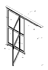
FIG. 1 is a perspective view of a first embodiment of the sliding door with
the sliding panel
partially open.
FIG. 2 is a perspective view of the first embodiment of the sliding door with
the sliding panel
partially open and broken away from the fixed panel.
FIG. 3 is a perspective view of the first embodiment of the sliding door with
the sliding panel
in the fully open position with both the sliding panel and the fixed panel
broken away from
the outer frame.
FIG. 4 is a detailed view of one embodiment of a header that may be used with
certain
embodiments of the sliding door.
FIG. 5A is a detailed view of one embodiment of a floor plate that may be used
with certain
embodiments of the sliding door.
FIG. 5B is a detailed view of the embodiment of the floor plate shown in FIG.
5A with the
sliding and fixed panels installed.
FIG. 6 is a detailed view of one embodiment of a carrier bar.
FIG. 7 is a detailed view of the embodiment of the carrier bar shown in FIG. 6
engaged with
the embodiment of a header shown in FIG. 4 with an outer plate removed for
clarity.
FIGS. 8A & 8B are detailed views of a sliding panel and fixed panel engaged
with the
embodiment of a header shown in FIG. 4 with the panels in the regular and
broke away
positions, respectively.
FIG. 8C is a detailed view of a sliding panel and fixed panel engaged with the
embodiment of
a header shown in FIG. 4 with the sliding panel in the broken away position.
FIG. 8D is a cross-sectional view of the embodiment of the sliding and fixed
panels, header,
and carrier bar shown in FIGS. 8A & 8B about the lock member in the sliding
panel top rail.
FIG. 9A is a perspective view of one embodiment of a guide bracket for use
with a sliding
panel.
4
CA 02832599 2013-10-07
WO 2012/139115 PCT/US2012/032766
FIG. 9B is a cross-sectional view of the embodiment of a guide bracket shown
in FIG. 9A
engaged with one embodiment of a fixed panel bottom rail about the fixed panel
post.
FIG. 9C is a cross-sectional view of the embodiment of a guide bracket shown
in FIG. 9A
engaged with one embodiment of a fixed panel bottom rail about the pivot pin.
FIG. 10A is a cross-sectional view of a top portion of the first embodiment of
the sliding door
about the sliding panel pivot pin.
FIG. 10B is a cross-sectional view of a top portion of the first embodiment of
the sliding door
about the lock member in the sliding panel.
FIG. 10C is a cross-sectional view of the top portion of the first embodiment
of the sliding
door shown in FIGS. 10A & 10B about the fixed panel pivot pin.
CA 02832599 2013-10-07
WO 2012/139115
PCT/US2012/032766
DETAILED DESCRIPTION¨ELEMENT LISTING
Description Element No.
Sliding door 10
Lock member 12
Pane groove 14
Pane 16
Outer frame 20
Header 22
Sliding track 22a
Stop block 23
Fixed panel guide 24
Guide interlock 24a
Guide detent 24b
Fixed panel pivot pin 25
First jamb 26
Second jamb 28
Sliding panel 30
Sliding panel first vertical rail 31a
Sliding panel second vertical rail 31b
Sliding panel top rail 32
Sliding panel interlock 32a
Sliding panel bottom rail 34
Guide block 35
Guide bracket 36
Bracket base 37
Guide pin 38
Pivot pin 39
Fixed panel 40
Fixed panel first vertical rail 41a
6
CA 02832599 2013-10-07
WO 2012/139115
PCT/US2012/032766
Fixed panel second vertical rail 41b
Fixed panel top rail 42
Fixed panel interlock 42a
Fixed panel bottom rail 44
Guide track 44a
Carrier bar 50
Carrier bar interlock 52
Carrier bar detent 52a
Roller 53
Sliding panel pivot pin 54
Floor plate 60
Panel bearing 62
Fixed panel post 64
DETAILED DESCRIPTION
Before the various embodiments of the present invention are explained in
detail, it is to be
understood that the invention is not limited in its application to the details
of construction and
the arrangements of components set forth in the following description or
illustrated in the
drawings. The invention is capable of other embodiments and of being practiced
or of being
carried out in various ways. Also, it is to be understood that phraseology and
terminology
used herein with reference to device or element orientation (such as, for
example, terms like
"front", "back", "up", "down", "top", "bottom", and the like) are only used to
simplify
description of the present invention, and do not alone indicate or imply that
the device or
element referred to must have a particular orientation. In addition, terms
such as "first",
"second", and "third" are used herein and in the appended claims for purposes
of description
and are not intended to indicate or imply relative importance or significance.
While the invention is susceptible of various modifications and alternative
constructions, a
certain embodiment is shown in the drawings and described in detail below. It
should be
7
CA 02832599 2013-10-07
WO 2012/139115 PCT/US2012/032766
understood, however, that there is no intention to limit the invention to the
specific form
disclosed, but on the contrary, the intention is to cover all modifications,
alternative
constructions and methods, and equivalents falling within the spirit and scope
of the
invention.
As shown in the drawings, a sliding door 10 according to the present
disclosure may include
at least one sliding panel 30 and at least one fixed panel 40 cooperatively
engaged with an
outer frame 20. The sliding panel 30 is configured so that it may move along a
header 22 and
slide next to the fixed panel 40 in linear plane that is parallel to but
offset from the fixed
panel 40. The sliding door 10 is configured so that the edge of the sliding
panel 30 adjacent
the sliding panel second vertical rail 3 lb may break away from the outer
frame 20 when the
sliding panel 30 is any position relative to the outer frame 20 or fixed panel
40 (e.g., fully
open, fully closed, partially open). Additionally, an edge of the fixed panel
40 adjacent the
fixed panel first vertical rail 41a may break away from the outer frame 20
when the sliding
panel 30 is fully open or nearly fully open. No floor track is required to
accommodate the
sliding panel 30 or fixed panel 40 breaking away from the outer frame 20. FIG.
1 shows the
first embodiment of the sliding door 10 wherein the sliding panel 30 is
partially open, and
FIG. 2 shows the sliding panel 30 with the edge thereof adjacent the sliding
panel second
vertical rail 31b broken away from the outer frame 20. FIG. 3 shows both the
sliding panel 30
and fixed panel 40 broken away from the outer frame 20. Each panel 30, 40 may
generally be
formed as a rectangle. The sliding panel 30 may include a sliding panel first
and second
vertical rail 31a, 31b and a sliding panel top and bottom rail 32, 34. The
fixed panel 40 may
include a fixed panel first and second vertical rail 41a, 41b and a fixed
panel top and bottom
rail 42, 44.
The embodiment of an outer frame 20 as disclosed herein generally includes a
header 22
abutting first and second jambs 26, 28 at either end of the header 22. It is
contemplated that
the jambs 26, 28 may be of the type used in conventional sliding doors, but
the sliding door
as disclosed and claimed herein is not so limited, and any suitable structure
and/or method
for engaging the sides of the sliding panel 30 and/or fixed panel 40 may be
used without
limitation.
FIG. 4 provides a detailed view of one embodiment of a header 22 that may be
used with the
illustrative embodiment of a sliding door 10. This embodiment of a header 22
may be formed
8
CA 02832599 2013-10-07
WO 2012/139115 PCT/US2012/032766
with a sliding track 22a therein to accommodate a carrier bar 50, as described
in detail below.
The sliding track 22a generally may extend along the entire length of the
header 22 and allow
the carrier bar 50 to slide laterally along the length of the header 22. The
header 22 may also
be formed with a stop block 23 at either end of the sliding track 22a adjacent
the fixed panel
first and second vertical rails 41a, 41b to limit the distance of travel for
the sliding panel 30.
The header 22 may also be formed with a fixed panel guide 24 along a portion
thereof for
selective engagement with the fixed panel top rail 42. The fixed panel guide
24 may include a
guide interlock 24a protruding from the fixed panel guide 24, which guide
interlock 24a
corresponds to a fixed panel interlock 42a formed in the fixed panel top rail
42. The fixed
panel guide 24 may also include a guide detent 24b for selective engagement
with a lock
member 12 positioned in the fixed panel top rail 42. The fixed panel 40 may
pivot with
respect to the outer frame 20 (e.g., when the fixed panel 40 is broken away
from the outer
frame 20) about a fixed panel pivot pin 25.
FIGS. 5A & 5B show one embodiment of a floor plate 60 that may be used with
the
illustrative embodiment of the sliding door 10. It is contemplated that the
floor plate 60 will
be secured to the floor/bottom surface to which the lower ends of the jambs
26, 28 extend,
but other configurations may be used without limitation. It is also
contemplated that the floor
plate 60 may be sized to not be exposed when both panels 30, 40 are broken
way.
Configuring the floor plate 60 so that it is located beneath both panels 30,
40 protects the
floor plate 60 from damage. The floor plate 60 may include a fixed panel post
64 that
pivotally engages the fixed panel bottom rail 44. Accordingly, when the fixed
panel 40 is
broken away from the outer frame 20, the fixed panel 40 is engaged with the
outer frame 20
solely through the fixed panel pivot pin 25 adjacent the fixed panel top rail
42 and the fixed
panel post 64 adjacent the fixed panel bottom rail 44. The floor plate 60 also
may include a
panel bearing 62 positioned between the fixed panel post 64 and the first jamb
26. The panel
bearing 62 may selectively engage the sliding panel bottom rail 34 to prevent
damage to any
components of the sliding door 10. That is, when the sliding panel 30 and
fixed panel 40 are
broke away together (as shown in FIG. 3), the panel bearing 62 may be
configured to accept
the transfer of the load from the sliding panel 30 and ensure that the sliding
panel 30 remains
straight and plumb in such circumstances.
One embodiment of a carrier bar 50 that may be used with the illustrative
embodiment of the
sliding door 10 is shown in FIG. 6. For the illustrative embodiment of the
sliding door 10, the
9
CA 02832599 2013-10-07
WO 2012/139115 PCT/US2012/032766
carrier bar 50 generally supports the majority of the weight of the sliding
panel 30 and
facilitates linear movement of the sliding panel 30 with respect to the outer
frame 20 and
fixed panel 40. The carrier bar 50 is generally positioned within the sliding
track 22a of the
header 22 during use, as best shown in FIG. 7. This embodiment of a carrier
bar 50 includes
two pairs of rollers 53 at either end thereof, which rollers 53 are rotatable
with respect to the
carrier bar 50 and generally facilitate movement of the carrier bar 50 from
one end of the
header 22 to the other along the sliding track 22a. The carrier bar 50 may be
formed with a
carrier bar interlock 52 extending therefrom, which corresponds to a sliding
panel interlock
32a formed in the sliding panel top rail 32. The carrier bar 50 may also
include a carrier bar
detent 52a for selective engagement with a lock member 12 positioned in the
sliding panel
top rail 32. The carrier bar 50 also may include a sliding panel pivot pin 54
for pivotal
engagement with respect to the sliding panel top rail 32 (e.g., when the
sliding panel 30 is
broken away from the outer frame 20 and/or fixed panel 40).
FIGS. 8A & 8B provide views of the illustrative embodiments of the sliding
panel 30 and
fixed panel 40 engaged with the illustrative embodiment of a header 22 in the
regular and
broken away positions, respectively. FIG. 8C provides a view of only the
sliding panel 30 in
the broken away position. The illustrative embodiment of the sliding door 10
as disclosed
herein is configured with lock members 12 formed as spring-loaded balls
mounted in the
sliding panel top rail 32 and fixed panel top rail 42, respectively. Each ball
engages its
respective detent 52a, 24b when the panels 30, 40 are in the regular position
(i.e., parallel
with respect to the header 22). The lock members 12 are designed so that a
specific amount of
force applied in a direction perpendicular to the length of the header 22
(preferably in the
direction of egress) dislodges the ball from the respective detents 52a, 24b,
thereby allowing
the respective panel 30, 40 to break away (i.e., pivot outward) from the outer
frame 20.
Accordingly, the sliding door 10 does not an operator to have special
knowledge of how the
sliding door 10 works for the operator to easily and effectively break away
either panel 30,
40. Furtheimore, a ball detent-type lock member 12 as disclosed in the
illustrative
embodiment requires less maintenance, service, and/or repairs as compared to
lever-actuated
flush bolt mechanisms of prior art sliding doors.
Other structures and/or methods for selectively securing the orientation of
the panels 30, 40
with respect to the header 22 with a predetermined amount of force may be used
with the
sliding door 10 as disclosed and claimed herein without limitation. For
example, in another
CA 02832599 2013-10-07
WO 2012/139115 PCT/US2012/032766
embodiment of the sliding door 10 not pictured herein, the lock member 12 may
be formed as
a sacrificial plastic dowel (rather than a spring-loaded ball), which must be
replaced after the
corresponding panel 30, 40 has broken away from the outer frame 20.
Accordingly, the
sliding door 10 is not limited to a lock member 12 and detents 52a, 24b, which
are for
illustrative purposes only.
FIG. 8D provides a cross-sectional view of the illustrative embodiments of the
header 22,
panels 30, 40, and carrier bar 50 when both panels 30, 40 are in the regular
position. As
shown, the guide interlock 24a engages the fixed panel interlock 42a, the
carrier bar interlock
52 engages the sliding panel interlock 32a, and the lock members 12 mounted in
the sliding
panel top rail 32 and fixed panel top rail 42 engage the carrier bar detent
52a and guide detent
24b, respectively, with the panels 30, 40 in this position.
A guide bracket 36 as shown in FIGS. 9A-9C may be pivotally mounted to the
sliding panel
bottom rail 34 on the end of the sliding panel bottom rail 34 adjacent the
sliding panel first
vertical rail 31a. The guide bracket 36 may be formed with a pivot pin 39
extending upward
from the bracket base 37 that may pivotally engage the sliding panel bottom
rail 34 and one
or more guide pins 38 that may pivotally engaged the fixed panel bottom rail
44 at a guide
track 44a formed therein. In the illustrative embodiment of the sliding door
10, when the
sliding panel 30 breaks away from the fixed panel 40, the sliding panel 30
pivots with respect
to the fixed panel 40 about the pivot pin 39 at the sliding panel bottom rail
34 and the sliding
panel pivot pin 54 at the sliding panel top rail 32. Because the majority of
the weight of the
sliding panel 30 is supported on the carrier bar 50, the guide bracket 36
serves mainly to
properly orient the sliding panel 30 with respect to the fixed panel 40
adjacent the sliding
panel first vertical rail 31a. However, in other embodiments of the sliding
door 10 the guide
bracket 36 may be designed to support more weight and/or forces from the
sliding panel 30
without limitation.
In light of the preceding description, the operation of the illustrative
embodiment of the
sliding door 10 should be apparent to those skilled in the art. The sliding
panel 30 may
pivotally engage a carrier bar 50 via a sliding panel pivot pin 54, and the
sliding panel 30
may pivotally engage a fixed panel 40 via a pivot pin 39 formed in a guide
bracket 36. The
sliding panel 30 in the illustrative embodiment of the sliding door 10 moves
linearly along
the header 22 via the rollers 53 rotatably secured to the carrier bar 50
adjacent the sliding
11
CA 02832599 2013-10-07
WO 2012/139115 PCT/US2012/032766
panel top rail 32 and via the engagement of the guide bracket 36 and guide
track 44a adjacent
the sliding panel bottom rail 34 such that the sliding door 10 is straight and
plumb during
operation. The fixed panel 40 of the illustrative embodiment of the sliding
door 10 may
pivotally engage a header 22 via a fixed panel pivot pin 25 adjacent the fixed
panel top rail 42
and may pivotally engage a floor surface via a fixed panel post 64 formed in a
floor plate 60
(which floor plate 60 may be affixed to the floor surface) adjacent the fixed
panel bottom rail
44.
The guide interlock 24a may engage a fixed panel interlock 42a to ensure
proper alignment of
the fixed panel 40 with respect to the outer frame 20 when the sliding door 10
is in the
normal position. A carrier bar interlock may engage a sliding panel interlock
32a to ensure
proper alignment of the sliding panel 30 with respect to the fixed panel 40
and outer frame 20
when the sliding door 10 is in the normal position. The various interlocks
24a, 42a, 32a, 52
may be formed to require a predetermined amount of force to become disengaged
with the
corresponding interlock 24a, 42a, 32a, 52. Accordingly, in certain embodiments
of the sliding
door 10, detents 24b and 52a and corresponding lock members 12 may not be
required.
Instead, the corresponding interlocks 24a, 42a, 32a, 52 may be configured with
complimentary lips (not shown) and/or other latch mechanisms that properly
secure the
respective interlocks 24a, 42a, 32a, 52 with one another unless acted upon by
an outside force
sufficient to break away the sliding panel 30 and/or fixed panel 40.
It is contemplated that for most applications it will be desirable to
construct the panels 30, 40,
outer frame 20, and carrier bar 50 of extruded aluminum, and that it will be
desirable to
construct the floor plate 60 from stainless steel.
It is contemplated that a prior art sliding door may be retrofit with specific
components so
that it may function as a sliding door 10 according to the illustrative
embodiment pictured
herein. As an example, the following describes modifications to a standard
Horton
Automatics brand sliding door to incorporate the functionality of present
sliding door 10. The
sliding panel first vertical rail 31a must be trimmed away from the sliding
panel bottom rail
34to allow the guide bracket 36 to move upward with respect to the floor
surface. By moving
the guide bracket 36 upward, it will now align with the guide track 44a formed
in the fixed
panel bottom rail 44.
12
CA 02832599 2013-10-07
WO 2012/139115 PCT/US2012/032766
It is contemplated that the guide bracket 36 will be manufactured specific to
the modified
design, and will vary depending on the type of prior art sliding door to be
modified. This is
necessary due to the unique nature of the specific models of prior art sliding
doors. Also
manufactured specifically depending on the model of prior art sliding door is
a guide block
35 as best shown in FIG. 5B. The guide block 35 may be secured to the bottom
surface of the
sliding panel bottom rail 32. The guide block 35 ensures that the sliding
panel 30 maintains a
minimum clearance above the floor when both panels 30, 40 are broken away (as
in FIG.
5B). The guide block 35 may serve to effectively transfer the weight of the
sliding panel 30 to
a pivot point located on the floor plate 60 adjacent the panel bearing 62. The
guide block 35
and panel bearing 62 may carry the sliding panel 30 when the guide track 44a
within the
fixed panel bottom rail 44 is moved out of standard operating position (i.e.,
broken away).
That is, a portion of the guide block 35 may engage the periphery of the panel
bearing 62,
which engagement ensures the sliding panel 30 remains straight and plumb as it
is rotated
about the axis of the sliding panel pivot pin 54 even if the fixed panel 40 is
also broken away.
Accordingly, it is contemplated that in the illustrative embodiment of the
sliding door 10 the
axis of rotation for the panel bearing 62 will be the same as that of the
sliding panel pivot pin
54. Certain embodiments of the sliding door 10 (e.g., most that are not a
retrofit of a prior art
sliding door) will not require a guide block 35, as the sliding panel bottom
rail 32 may be
configured with a load-bearing portion adjacent the sliding panel first
vertical rail 31a
integral to the sliding panel bottom rail 32.
The fixed panel 40 for this model of prior art sliding door will require
significant
modification to perform as a fixed panel 40 according to the present sliding
door 10. The
overall height of the fixed panel 40 must be reduced to allow for the guide
track 44a in the
fixed panel bottom rail 44 and the guide interlock 24a, fixed panel interlock
42a, and fixed
panel pivot pin 25 to facilitate the break away function of the fixed panel
40.
Either the fixed panel second vertical rail 41b or the first jamb 26 may be
changed to a radius
nosed type rail (preferably having full length weather striping installed
along the entire height
of the fixed panel 40). This will allow the fixed panel 40 to maintain a
proper seal between
the first jamb 26 and the fixed panel second vertical rail 41b, as well as
provide necessary
clearances for the break away function.
13
CA 02832599 2013-10-07
WO 2012/139115 PCT/US2012/032766
The fixed panel guide 24 formed in the header 22 and the fixed panel pivot pin
25 may
interact with the fixed panel top rail 42 to form a scissor-type design, which
allows for
maximum support for the fixed panel 40 in the standard operating position, and
adequate
support during break away situations.
The fixed panel bottom rail 44 may be cut down so that it has a smaller height
and relocated
upward on the fixed panel first and second vertical rails 41a, 41b. The guide
track 44a may
then be secured to the fixed panel bottom rail 44. A u-channel member (not
shown) may then
be added to the fixed panel bottom rail 44 to complete the modification. This
u-channel may
be configured to provide for a mounting location for the fixed panel post 64
of the floor plate
60 if not present in the guide track 44a as well as providing the proper
overall panel height
for the fixed panel 40.
The floor plate 60 may be specifically constructed for the model of prior art
sliding door that
is converted to a sliding door 10 according to the present disclosure. It is
contemplated that at
least the specific orientation of the panel bearing 62 and fixed panel post
with respect to one
another and the members of the outer frame 20 may vary from one prior art
sliding door
model to the next.
With these modifications complete a conventional Horton Automatics ICU-type
sliding door
unit can be converted into a trackless unit according to the present sliding
door 10, with the
ability of the sliding panel 30 to break away or panic open at any point in
the sliding panel's
30 travel. Also both panels 30, 40 may be broken away to facilitate moving
large items
through the sliding door 10. These modifications can easily be applied to any
other
conventional ICU sliding doors with the same result.
Those skilled in the art will readily appreciate that the sliding door 10
disclosed and claimed
herein may be incorporated into alternate conventional sliding door units as
well as
implemented in OEM door units. Although the illustrative embodiments are
directly mainly
toward retrofitting a prior art Horton Automatics sliding door, the scope of
the sliding door
is not so limited and applies to retrofitting other types/brands of prior art
sliding doors in
accordance with the present art sliding door 10 as well as producing a sliding
door 10 with
the capability of the sliding panel 30 to break away in any position and the
sliding and fixed
14
CA 02832599 2013-10-07
WO 2012/139115 PCT/US2012/032766
panels 30, 40 to both break away when the sliding panel 30 is fully or near
fully open
integrated into the sliding door 10 at initial production.
The materials used to construct the sliding door 10 and various elements
thereof will vary
depending on the specific application, but it is contemplated that metal,
metallic alloys, glass,
synthetic materials, glass, and/or combinations thereof will be especially
useful for most
applications. Accordingly, the above-referenced elements may be constructed of
any material
known to those skilled in the art or later developed, which material is
appropriate for the
specific application of the sliding door, without departing from the spirit
and scope of the
sliding door 10 as disclosed and claimed herein.
Having described the preferred embodiments, other features of the sliding door
10 will
undoubtedly occur to those versed in the art, as will numerous modifications
and alterations
in the embodiments as illustrated herein, all of which may be achieved without
departing
from the spirit and scope of the sliding door 10. Accordingly, the methods and
embodiments
pictured and described herein are for illustrative purposes only.
It should be noted that the sliding door 10 is not limited to the specific
embodiments pictured
and described herein, but are intended to apply to all similar apparatuses and
methods for
producing a sliding door 10 or retrofitting a prior art sliding door such that
the resulting
sliding door 10 allows the sliding panel 30 to break away when the sliding
panel 30 is in any
position and allows both the sliding panel 30 and fixed panel 40 to break away
when the
sliding panel 30 is in the fully open position. Modifications and alterations
from the described
embodiments will occur to those skilled in the art without departure from the
spirit and scope
of the sliding door 10.