Note : Les descriptions sont présentées dans la langue officielle dans laquelle elles ont été soumises.
CA 02833229 2013-11-18
AXIAL TURBOMACHINE BLADE WITH PLATFORMS HAVING AN ANGULAR
PROFILE
Field
[0001] The invention relates to the rotor blades of an axial turbomachine,
more
particularly to the stator of an axial turbomachine. The invention also
relates
to a stator and an axial turbomachine comprising the stator. The invention
relates to the angular setting of the blades of an axial turbomachine. The
invention also relates to a method of assembling the axial turbomachine,
particularly its stator(s).
Background
[0002] In order to achieve high performance, axial turbomachines have several
compressors and possibly several turbines which respectively compress and
expand air. Each compressor and each turbine commonly has several rows
of alternating rotor and stator blades. The pitch angles of the blades on
successive stages differ incrementally, thereby gradually compressing the air
before it enters the combustion chamber and gradually expanding the
exhaust gas.
[0003] The pitch is a factor that is calculated for each blade row in order to
optimise
the efficiency of a given row, and the overall performance of a turbomachine.
To construct such a row, several solutions are possible. For example, the
array can be fabricated from blades welded to a ferrule, housing or rotor.
The blades may also be attached with threaded studs or lockbolts. By
providing each blade with two fixing pins it is prevented from rotating.
However, this solution is particularly heavy because of the existence of the
second fixing pin.
[0004] To save weight, it is advantageous to use only one fixing pin. However,
this
latter can no longer prevent the blade from rotating so that it maintains its
pitch. The pitch may nevertheless be maintained by fitting the blade with a
- 1 -
CA 02833229 2013-11-18
platform which is placed in an annular groove the shoulders of which offer an
abutment at the corners of the rectangle.
[0005] Patent EP 1936121 B1 discloses a turbomachine having such a blade with
a
platform housed in such an annular groove. The blade is fastened by means
of a nut screwed onto its threaded shaft. But this solution has manufacturing
constraints. It requires a groove, thereby involving thickening in one place.
If
one of the materials of which a platform or the groove is made has
insufficient hardness, this material may be deformed as the nut is being
tightened. Therefore, the accuracy of the blade pitch may be degraded.
Summary
The technical problem
[0006] The invention aims to solve at least one of the problems presented by
the
prior art. The invention aims to provide a solution for setting the pitch
angle
of a stator blade. More particularly, the invention aims to provide a blade
design that reduces the turbomachine's manufacturing costs while ensuring
the pitch is set correctly.
Technical solution
[0007] The invention relates to a stator blade of an axial turbomachine,
intended to
be fixed to a ferrule in an annular row of identical blades, the blade
comprising a platform with a means of attachment to the ferrule enabling
angular adjustment of the blade, an upstream edge, a downstream edge and
two lateral opposing edges, wherein the shape of the platform has at each of
its lateral edges a angular profile designed to marry with the contiguous
edge of the platform of an identical adjacent blade so as to ensure the
angular positioning of the blade in at least one direction of rotation.
[0008] The lateral edges may be made to line up generally by transverse
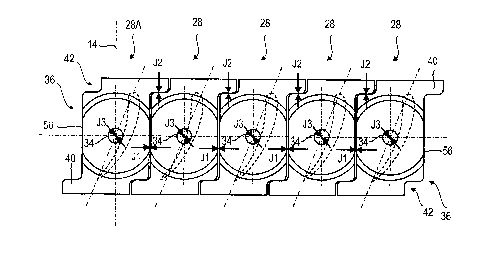
translation. Transverse translation means a translation along the direction of
the circumference of the blade row.
- 2 -
CA 02833229 2013-11-18
[0009] The lateral edges may be configured to line up predominantly along a
rotation in space around the turbomachine's axis of rotation. This precision
is useful for blade rows located on an inclined surface. Geometrically, this
angle results in a reduction of the widths of the platforms downstream or
upstream.
[0010] According to an embodiment, the transverse width of the platform
remains
substantially constant.
[0011] According to an embodiment, the angular profile has at least one
contact
part generally inclined to the axis of the turbomachine by an angle greater
than or equal to 20 , preferably greater than or equal to 45 , more preferably
equal to or greater than or equal to 70 . Optionally, this angle may be
substantially equal to 90 .
[0012] According to an embodiment, the, or at least one of the, contact
part(s) of
the angular profile is generally straight.
[0013] According to an embodiment, the upstream and downstream edges are
generally straight and parallel to the axis of the turbomachine being
generally perpendicular to the said edges.
[0014] According to an embodiment, the means of attachment on the platform
comprises means of clamping by rotation, arranged essentially at the centre
of the platform, the or at least one of those contact part(s) of the angular
profile being positioned to bear against the corresponding profile of the
contiguous edge of the adjacent blade when the platform rotates in the
direction of clamping of the means of attachment.
[0015] According to an embodiment, the contact part of the angular profile is
part of
a projected area of the corresponding lateral edge of the platform.
[0016] According to an embodiment, each of the lateral edges of the platform
further comprises a recessed area, the projected and recessed areas being
located and positioned on either side of a transverse axis passing through
the blade's centre of rotation. Where the recessed area is adjacent to one of
the upstream and downstream edges, it has in addition a cut-out.
[0017] According to an embodiment, the profile of each of the lateral edges of
the
platform has a generally square central part and a contact part upstream or
- 3 -
CA 02833229 2013-11-18
downstream, preferably at each of the two upstream and downstream
positions.
[0018] According to an embodiment, the means of attachment comprises a pin
extending from one face of the platform, the said face acting as a face for
mounting to the ferrule.
[0019] The invention also relates to the stator of an axial turbomachine
comprising
a ferrule with an inner surface and an annular row of blades comprising
identical platforms arranged side-by-side on the inner surface of the ferrule,
wherein the blades are in accordance with the invention, several adjacent
blades having at least a part of their angular profile on the same lateral
side
bearing against the corresponding profile of the adjacent blade.
[0020] According to an embodiment, the means of attachment on the platform
comprises a means of clamping by rotation, arranged essentially at the
centre of the platform, the or at least one of those contact part(s) of the
angular profile being positioned to bear against the corresponding profile of
the contiguous edge of the adjacent blade when the platform rotates in the
direction of clamping of the means of attachment, and the blade platforms
have some mechanical clearance between them corresponding to a
tolerance for the angular positioning of the blades, the angular profiles of
the
plurality of consecutive blades being in mutual contact in the direction of
clamping the means of attachment.
[0021] According to an embodiment, the plurality of adjacent blades are
configured
to rotate more than 20', preferably more than 40', more preferably more than
80', even more preferably more than 120' around their means of attachment
when they are not clamped down.
[0022] According to another embodiment, the ferrule has a substantially
constant
thickness.
[0023] According to an embodiment, the ferrule has an essentially smooth
mounting
surface in contact with the platforms.
[0024] According to yet another embodiment, the housing is made of composite
material.
- 4 -
CA 02833229 2013-11-18
[0025] The invention also relates to a compressor having at least one annular
row
of blades, wherein the blades of the blade row are in accordance with the
invention.
[0026] The invention also relates to an axial turbomachine with a compressor
and/or turbine fitted with a stator, wherein the stator is in accordance with
the
invention, and/or the compressor is in accordance with the invention. -
[0027] The invention also relates to a method of fixing an annular row of
blades on
a stator ferrule of an axial turbomachine, the blades being in accordance
with the invention and the means of attachment of the platforms comprising
a means of clamping by rotation, located essentially at the centre of the
platforms, the or at least one of the contact part(s) of the angular profiles
being positioned so as to bear against the corresponding profile of the
corresponding edge of the adjacent blade when the platforms rotate in the
direction of clamping of the means of attachment, wherein it comprises the
following steps:
[0028] (a) fixing a reference blade substantially in the final angular
position of the
said row,
[0029] (b) successively placing a plurality of blades on the ferrule so as to
construct
the said blade row with the reference blade,
[0030] (c) successively clamping the means of attachment of the plurality of
blades
starting from the reference blade, so as to successively bring the or at least
one of the contact part(s) of the angular profile of each of the said blades
to
bear on the corresponding contiguous profile of the previous blade.
[0031] According to an embodiment, step (b) covers only part of the
circumference
of the stator; step (a) is carried out at several locations on the said
circumference.
[0032] According to an embodiment, the reference blade is a dummy blade
equivalent to at least two contiguous blades, and in that the method further
comprises the step of:
[0033] (d) replacing the dummy reference blade(s) by blades in accordance with
the
other blades.
- 5 -
CA 02833229 2013-11-18
[0034] According to an embodiment, the number of reference blades is less than
1/10 of the total number of stator blades, preferably less than 1/15, more
preferably less than 1/20.
[0035] The invention allows the pitch to be set accurately for a blade row
without
having recourse to a shoulder on the mounting, such as a ferrule. In this
way, the means of support can be made lighter. This feature also enables a
mounting to be made of a composite material, which provides a further
opportunity to reduce weight.
[0036] The pitch setting achievable by the invention requires conventional
surface
finishes; the mechanical clearances can be increased locally. Thus, the
invention reduces manufacturing costs. In addition, the invention simplifies
the measurements and tests necessary to achieve a given pitch. This feature
also enables savings to be made.
Short description of the diagrams
[0037] Figure 1 shows an axial turbomachine in accordance with the invention.
[0038] Figure 2 is a view of the low-pressure compressor of the axial
turbomachine
of Figure 1, the compressor having several stators in accordance with the
invention.
[0039] Figure 3 is a first view of an axial turbomachine blade according to a
first
embodiment of the invention.
[0040] Figure 4 is a second view of the blade in Figure 3.
[0041] Figure 5 illustrates an annular row of blades of a stator, the blades
corresponding to Figures 3 and 4.
[0042] Figure 6 illustrates a blade according to a second embodiment of the
invention.
[0043] Figure 7 illustrates a blade according to a third embodiment of the
invention.
[0044] Figure 8 illustrates a blade according to a fourth embodiment of the
invention.
[0045] Figure 9 illustrates a blade according to a fifth embodiment of the
invention.
- 6 -
CA 02833229 2013-11-18
[0046] Figure 10 illustrates a blade according to a sixth embodiment of the
invention.
Description of the embodiments
[0047] In the following description, the terms 'inner' and 'outer' refer to a
position
relative to the axis of rotation of an axial turbomachine. The terms
'transverse' and 'lateral' are expressed with respect to the longitudinal
direction of the turbomachine and the stator, this direction corresponding to
the axis of rotation of the machine.
[0048] Figure 1 shows an axial turbomachine. In this case it is a double-flow
turbojet. The turbojet 2 comprises a first compression stage, a so-called low-
pressure compressor 4, a second compression stage, a so-called high
pressure compressor 6, a combustion chamber 8 and one or more turbine
stages 10. In operation, the mechanical power of the turbine 10 is
transmitted through the central shaft to the rotor 12 and drives the two
compressors 4 and 6. Reduction mechanisms may increase the speed of
rotation transmitted to the compressors. Alternatively, the different turbine
stages can each be connected to compressor stages through concentric
shafts. These latter comprise several annular rotor blade rows associated
with stator blade rows. The rotation of the rotor around its axis of rotation
14
generates a flow of air and gradually compresses it up to the inlet of the
combustion chamber 8.
[0049] An inlet fan, commonly designated a 'turbofan' 16, is coupled to the
rotor 12
and generates an airflow which is divided into a primary flow 18 passing
through the various above-mentioned levels of the turbomachine, and a
secondary flow 20 passing through an annular conduit (shown in part) along
the length of the machine and then rejoins the main flow at the turbine
outlet.
[0050] Figure 2 is a sectional view of a low-pressure compressor 4 of an axial
turbomachine 2 such as that of Figure 1. Part of the turbofan 16 can be
seen, as can the splitter nose 22 between the primary 18 and secondary 20
airflows. The rotor 12 comprises several rows of rotor blades 26, for example
-7-
CA 02833229 2013-11-18
three, and several rows of stator blades 28, for example four. Each row of
stator blades 28 is associated with a row of rotor blades 26 for straightening
the airflow so as to convert the velocity of the flow into pressure. Each pair
of
rotor blade rows with the associated stator form a stage of the compressor 4.
[0051] The low-pressure compressor 4 has a mechanically welded stator with a
housing 30 acting as a mounting for the stator blades 28. The housing 30
forms a wall indirectly defining the primary flow 18. It may have a
substantially smooth inner surface, preferably free of any lip. It has a shape
of revolution about the axis of rotation 14 of the low-pressure compressor 4,
which corresponds to the axis of the turbomachine. Its profile of revolution
can be curved and closer to the axis 14 downstream. The housing 30 may
comprise or form a plurality of annular members, such as ferrules arranged
axially relative to each other so as to extend along the length of the
compressor. It is noteworthy that at the fourth row of stator blades 28, the
housing has an inclination greater than 150. Optionally, the angle may be
greater than 25 .
[0052] The stator blades 28 include platforms 32 pressed against the inner
surface
of the housing 30. They can be essentially flat or curved surfaces. Their
surfaces in contact with the housing 30 are generally smooth. The contact
between the platform 32 and the inner surface of the housing 30 is almost
planar. The inclination of the platforms 32 with respect to the axis of
rotation
14 increases substantially in the downstream rows.
[0053] Strips 35 of abradable material are applied between the rows of stator
blades 28. More specifically, these strips 35 are located between the
platforms 32 of the different rows of stator blades 28. The thickness of the
strips is substantially equal to the overall thickness of the platforms 32.
[0054] The stator blades 28 are attached to the housing 30 by a means of
attachment 34. The means of attachment 34 extends from its platform in a
direction opposite to the aerodynamic part of the blade. The means of
attachment are substantially cylindrical. The means of attachment 34 may
comprise a fixing pin such as a screw or stud designed to have nut fitted.
Preferably, the means of attachment of each blade comprises substantially a
- 8 -
CA 02833229 2013-11-18
fixing pin. These are inserted into openings made in the housing 30.
[0055] The means of attachment comprise means of clamping, for example nuts
designed to be fitted to a screw or stud. The clamping force of the means of
clamping can easily rotate a blade about its means of attachment 34 since
its platform 32 is smooth and is in planar contact with the housing 30.
[0056] In order to inhibit this rotation the platforms 32 have special
contours. Figure
3 is a platform 32 according to a first embodiment of the invention. The
platform 32 may have a generally quadrilateral shape such as a rectangle, a
trapezium or a parallelogram. The contour of the platform 32 comprises
lateral opposite edges 36 and two transverse edges 38 which are arranged
perpendicularly to the axis of rotation 14, one being upstream of the blade
body and the other being downstream. The platform 32 has a reverse Z-
shape. The lateral edges 36 have an angular profile and embody physical
interference, thus preventing rotation.
[0057] The angular profiles of the edges 36 each comprise a contact part 48
coming
into contact with the corresponding part of the adjacent edge of an adjacent
blade. This contact embodies physical interference. The contact parts 48
each have a projecting part 40. Each contact part 48 is inclined relative to
the axis of rotation of the turbomachine by an angle greater than 100,
preferably greater than 30 , more preferably greater than 60 . This angle
optionally is roughly equal to 90 . The angular profiles also each comprise a
recessed area 42 relative to the general rectangular shape of the platform.
The recessed area matches the projection on the opposite edge.
[0058] According to a preferred embodiment of the invention, the platforms 32
on
one row of blades are identical. Thus, a projecting area of a platform 32 may
marry with a recessed area or cut-out 42 of an adjacent platform 32. The
contiguous lateral edges 36 interpenetrate and stop the platforms 32 rotating
around at least one, optionally two, axis/axes of rotation about their means
of
attachment 34. Thus, the angular orientation of a stator blade 28 can be
controlled precisely during assembly. The angular orientation of stator
blades can be achieved reliably and repeatedly. Pitch measurement
activities can be reduced, possibly eliminated.
- 9 -
CA 02833229 2013-11-18
[0059] The angular orientation or pitch of a blade is determined by the angle
which
the chord 44 of a blade makes with the axis of rotation 14 of the
turbomachine 2. The chord used for this measurement is that at the junction
with the platform 32.
[0060] The contact part 48 from one lateral edge bears against the
corresponding
part of the contiguous edge of the adjacent blade when the blade rotates as
it is being clamped. In the platform shown in Figure 3 clamping causes
clockwise rotation. The contact part is generally parallel to the transverse
direction, corresponding to the circumferential direction of the blade row.
For
this reason, the contact force between two adjacent blades generates little or
no force in the transverse direction. In addition, this contact enables
angular
positioning independent of the tolerances in the distances between the
blades, more precisely between the openings in the ferrule holding the
means of attachment 34. Tolerances in the distances between the openings
are larger than those relating to their alignment along the circumference of
the ferrule.
[0061] The platform 32 is made of metal, preferably titanium. It can be
integral with
the body of the blade. To meet a specific shape, its contour is machined and
possibly adjusted to meet strict tolerances.
[0062] The lateral edges 36 have similar profiles, preferably identical. Note
that the
profiles in generally coincide if they are translated over a distance equal to
the width of the platform 32, in a direction oriented along the transverse
edges (upstream and downstream) 38. The platform 32 has a generally
constant width. The width may decrease substantially downstream due to
the curvature of the housing 30. The width is measured transversely. The
two profiles are substantially symmetrical with respect to the centre of the
means of attachment.
[0063] The two profiles can be matched exactly in the case of the platforms 32
by
translation parallel to the axis of rotation 14. Regarding the inclined
platforms
32, especially those in the last row of stator blades, the two profiles are
significantly divergent. Both profiles can be matched by performing an
isometry, namely a rotation about the axis of rotation 14 of the turbomachine.
- 10 -
CA 02833229 2013-11-18
[0064] The platform 32 has a thickening 46. This latter forms a disc cut
laterally by
the longitudinal edges 36. Due to the awkward shape of the ferrule or
housing 30, the contact with the disc can be at two points or two upstream
and downstream edges. These contacts facilitate a slight degree of
movement when mounting a blade row and improve the positioning and
automatic orientation of the blades.
[0065] Figure 4 shows the stator blade 28 of Figure 1, according to the first
embodiment of the invention. It has a body 50, or airfoil 50, forming a
contoured surface designed to extend into the primary flow 18. Its shape can
change the direction of flow. The head of the blade may have devices for
attachment to an inner ferrule.
[0066] At the thickening 46, the lateral edges 36 have a greater height. Thus,
the
platforms offer better locking against rotation and tangential translation.
The
means of attachment 34 may comprise a smooth cylindrical surface 54
which is inserted into the thickness of the housing 30. It also includes a
threaded portion 52 outside the housing 30.
[0067] To facilitate the installation of a blade row, mechanical clearances
are
provided in the platforms 32 and the means of attachment 34. Figure 5
shows part of a row of blades according to the first embodiment of the
invention. The row, which generally forms a ring, in shown in plan view here.
To enable the row to be assembled, a mechanical clearance at the lateral
edges 36 is defined. J1 is the first mechanical clearance between the
straight portions 56 of the lateral edges 36, and J2 is the second mechanical
clearance between the curved parts of the lateral edges 36. The straight
parts 56, of two, preferably of all, the adjacent blades may be spaced apart
from each other. The second mechanical clearance is at the contacts
between the projections 40 and the recessed areas 42, more precisely
between the contact parts.
[0068] The first clearance J1 allows traverse movement of the platforms 32 in
combination with the clearance at the means of attachment 34. The second
clearance J2 enables the platforms 32 to rotate, and a displacement in the
longitudinal direction of the machine, in combination with the clearance J3 in
-11-
CA 02833229 2013-11-18
the means of attachment 34. Clearances J2 and J3 can be between 0.01
mm and 0.30 mm, preferably between 0.01 mm and 0.20 mm. The
clearances can be different, especially J1, which can be larger than J2 or J3.
It may, for example, be greater than 0.05 mm, or even greater than 0.50 mm.
For aerodynamic reasons, it may be worthwhile to seal the clearance J1 with
a silicone material. The smaller the required clearances, the greater must be
the manufacturing precision, as when the range of clearances is narrow.
These clearances enable relative rotation between the platforms 32 and
therefore a change in the angular orientation of the blades.
[0069] When the blades are being designed, a theoretical angular orientation
to
achieve a desired operational performance is defined. At the same time as
the design, the shapes of the lateral edges are fixed. To enable the
assembly of a blade row, the mechanical clearances J1, J2 and J3 must be
defined. Now, these latter enable the blades to rotate when tightening the
means of attachment, which has the effect of twisting the angular
orientations of the blades. Note that these errors in the blades' angular
orientation are in the direction of rotation of the means of clamping. These
errors also have an average value with a small standard deviation.
Therefore, the blades are produced with an angular compensation for
offsetting the error in angular orientation. Since the standard deviation of
the
error is small, the compensation angle allows for a blade row in which the
variation in angular orientation is acceptable. Advantageously, the average
angular orientation error and/or compensation angle is greater than 5',
preferably greater than 30'. The compensation angle is generally
proportional to the clearances J1, J2 and J3. Note that the compensation
angle is oriented in the opposite direction to that of the tightening of the
means of clamping. The calculation of the compensation angle may be
based on average values of the mechanical clearances, as well as their
standard deviations. Calculating the pitch differences may also take into
consideration the geometric tolerances of the platform surfaces.
[0070] The invention exploits the clamping force and the geometry of the
platform
contours. The clamping force tends to make the platforms rotate in a given
- 12 -
CA 02833229 2013-11-18
direction proportional to the size of the clearances. Making blades with a
geometry that counters the positioning error enables the pitch to be set
during assembly in accordance with an acceptable average value and a
reduced standard deviation.
[0071] The teaching of the invention can be applied to a stage with stator or
rotor
blades that have platforms coming into contact with each other, and which
are attached to a mounting using a means of fastening that can affect the
angular orientation of the blades in one direction during the tightening of
the
means of clamping. The teaching of the invention can be used for blades
whose lateral edges are substantially straight and free of bends.
[0072] Several methods can be used to assemble a blade row on its support. The
method may comprise a step of successively placing blades in the housing
30. Then the method may comprise a step of successively tightening the
means of clamping in turn, moving from one blade to the adjacent one.
Attaching can be carried out from several starting points or starting blades.
Interleaving platforms enables blade pitches to be maintained.
[0073] To improve the accuracy of setting the pitch, the method may include a
preliminary step for mounting at least one reference blade 28A or marker
blade. Preferably, at this stage, several reference blades are used, for
example six for a row having a hundred and twenty blades in all. The
reference blade 28A can be a conventional blade whose pitch is set and
fixed after being attached. Then begins the step of placing the blades so as
to form a blade row. At this point, the blades do not necessarily have their
pitch set correctly. Then begins the step of successive clamping, using the
means of clamping. Tightening the nuts is continuous, proceeding from one
blade to its neighbour. Attachment may be performed starting from one side
of a reference blade 28A, or from both sides.
[0074] If the manufacturing precision of the blades 28 is not as great, it is
advantageous to increase the number of reference blades. Manufacturing
costs can thus be reduced. Conversely, it is possible to reduce the number
of reference blades if manufacturing precision is improved. Thus, the costs
of pitch adjustment and testing of the reference blades can be reduced.
-13-
CA 02833229 2013-11-18
[0075] To further increase the accuracy of setting the pitch, it is possible,
during the
assembly stage, to use, as well as at least one reference blade, additional
reference blades of another type. Such blades are similar to conventional
blades, but have a widened platform and two means of attachment 34.
These are fitted into two spaced holes, thereby precisely orienting the
reference blade. The platforms have lateral edges enabling the adjacent
blades to be rotationally locked at the pitch when they are assembled. The
reference blade can be a dummy blade that includes a platform 32 with two
means of attachment 34. The greater the distance between the holes being
used, the greater is the precision with which the pitch can be set. This
precision is achieved without the need to perform any measurement and
testing operations. Thus it is possible to save time and effort.
[0076] After the step of attaching the blades, the method comprises a step of
replacing the dummy blades. This step leaves free spaces in the blade row
formed during the step of placing the blades.
[0077] Therefore, the method comprises a further step of inserting and
attaching the
blades in the free spaces. These last blades have the benefit of the precision
mounting of the blades that were in contact with the reference blades that
were attached during the clamping step.
[0078] Figure 6 illustrates a platform according to a second embodiment of the
invention. Figure 6 has the same numbering scheme as in previous figures
for the same or similar elements, but the numbering is incremented by 100.
[0079] The platform 132 has a generally rectangular shape. It has transverse
edges
138 and lateral edges 136 that each have mating tabs 140 and recesses
142. The tabs 140 and the recesses 142 are at some distance from the
transverse edges 138. Their corners are rounded; they may, however
project, for example at right angles. Each of the tabs 140 includes two
contact parts, depending on the direction of blade rotation. The platform can
thus ensure rotational locking in both rotational directions.
[0080] The platform 132 is more elongated than that shown in Figure 3. It is
suitable
for a blade in which the pitch angle is closer to 00, for example less than
100.
On this platform 132, the means of attachment are offset in relation to the
- 14 -
CA 02833229 2013-11-18
body of the blade. Thus, the means of attachment may be moved away so
as to correspond with the structure of a specific turbomachine.
[0081] Figure 7 illustrates a platform according to a third embodiment of the
invention. Figure 7 has the same numbering scheme as in Figures 3 and 4
for the same or similar elements, but the numbering is incremented by 200.
Specific numbers are used for items specific to this embodiment.
[0082] Platform 232 is generally S-shaped so as to be suitable for a means of
attaching with a right-hand thread. It comprises three parallelograms and is
symmetrical with respect to its attachment axis 234. The profiles 236 of the
lateral edges each have a central contact part 248 and two upstream and
downstream parts 249. The upstream and downstream parts 249 are
substantially parallel and the same length. The contact parts 248 form an
angle close to 45 with the transversal direction and are in contact with the
contact parts 248 of the adjacent blades. This platform configuration is
designed for a means of attachment which is tightened clockwise. For a
means of attachment that is tightened anti-clockwise, the profiles should be
reversed, that is to say, symmetrical with those of Figure 7 with respect to
the longitudinal direction of the machine.
[0083] Figure 8 illustrates a platform according to a fourth embodiment of the
invention. Figure 8 has the same numbering scheme as in Figures 3 and 4
for the same or similar elements, but the numbering is incremented by 300.
Specific numbers are used for items specific to this embodiment.
[0084] Platform 332 is similar to that shown in Figure 3. It comprises two
generally
parallel lateral edges 336. It has a general parallelogram shape with a
reverse Z-shape. The general direction of the parallelogram is substantially
parallel to the chord of the blade 344. By general direction is meant the
direction of the long sides of the parallelogram. The platform 332 can be
designed for blades having a pitch angle opposite to that shown in Figure 3.
[0085] Platform 332 includes projections 340 and recesses 342 cut out from
within
the general shape of a parallelogram. The projections 340 form an acute
angle with the longitudinal portions 354 of the lateral edges 336.
[0086] Figure 9 illustrates a platform according to a fifth embodiment of the
- 15 -
CA 02833229 2013-11-18
invention. Figure 9 has the same numbering scheme as in Figures 3 and 4
for the same or similar elements, but the numbering is incremented by 400.
[0087] Platform 432 is generally parallelogram-shaped. It includes lateral
edges 436
that form arc-shaped contact parts 448. The lateral edges 436 marry up with
the adjacent lateral edges for most of their length. Part of their length
cannot
be in contact with the lateral edge of the adjacent blade.
[0088] Figure 10 illustrates a platform according to a sixth embodiment of the
invention. Figure 10 has the same numbering scheme as in Figures 3 and 4
for the same or similar elements, but the numbering is incremented by 500.
[0089] The blade comprises a platform 532 and a means of attachment 534. The
platform 532 is generally C-shaped. The shape can be a reversed C. This
platform is symmetrical relative to a transverse plane passing through the
means of attachment 534.
[0090] Platform 532 includes lateral edges 536 and transverse edges 538. Each
of
the lateral edges 536 includes two contact parts 548. One contact part is on
an upstream part of the edge and the other on a downstream part. These
have opposite inclinations, which has the advantage that the lateral edge in
question can bear against the adjoining edge of an adjacent blade
independent of the direction of rotation.
- 16-