Note : Les descriptions sont présentées dans la langue officielle dans laquelle elles ont été soumises.
CA 02834434 2013-10-25
WO 2012/158112 PCT/SE2012/050527
1
METHOD FOR COOLING AND INCREASING ENERGY YIELD OF A
TORREFIED PRODUCT
Technical field
The present invention relates to the field of torrefaction of biomass. In
particular, it
relates to a method and a system for efficient cooling of torrefied material
which also
increases energy yield and hydrophobicity of the torrefied product and
decreases
clogging of the cooling device.
Background
To be able to compete with and replace fossil fuel energy carriers such as
coal, oil
and natural gas, lignocellulosic biomass would benefit from some form of pre-
treatment method to overcome inherent drawbacks. The pre-treatment method
torrefaction has been shown to improve biomass fuel qualities such as energy
density, water content and milling, feeding and hydrophobic properties [1-4].
These
improvements establish torrefaction as a key process in facilitating an
expanding
market for biomass raw materials. Torrefaction is a thermal pre-treatment
method
that normally takes place in a substantially inert (oxygen free) atmosphere at
a
temperature of about 220-600 C. During the process course a combustible gas
comprising different organic compounds is produced from the biomass feedstock
in
addition to the torrefied biomass.
The process of producing a torrefied material from lignocellulosic biomass can
be
said to include four stages:
1) a drying step, wherein free water retained in the biomass is removed;
2) a heating step in which physically bound water is released and the
temperature of
the material is elevated to the desired torrefaction temperature;
3) a torrefaction stage, in which the material is actually torrefied and which
starts
when the material temperature reaches about 220 C -230 C. During this stage,
the
biomass partly decomposes and releases different types of volatiles, such as
hydroxy
acetone, methanol, propanal, short carboxylic acids etc. In particular, the
torrefaction
stage is characterized by decomposition of hemicellulose at temperatures from
220 C -230 C, and at higher torrefaction temperatures cellulose and lignin
also starts
CA 02834434 2013-10-25
WO 2012/158112 PCT/SE2012/050527
2
to decompose and release volatiles; cellulose decomposes at a temperature of
305-
375 C and lignin gradually decomposes over a temperature range of 250-500 C;
4) a cooling step to terminate the process and facilitate handling. The
torrefaction
process is terminated as soon as the material is cooled below 220 C -230 C.
Summary of the present disclosure
During the cooling process of torrefied material, the material continues to
release
gases until the temperature of the material is decreased below about 200 C.
However, the material need to be further cooled to below 130 C to ensure safe
self
ignition temperatures. Therefore, in the prior art, torrefied material have
been directly
cooled in a cooling device such as a screw cooler to decrease the temperature
to
below 130 C, see e.g. W02009/151367 Al. One problem with this approach is that
the gases released from the torrefied material during the cooling process will
condense on cold surfaces within the cooling device leading to fouling or
clogging of
said device. Another drawback with this solution is that the cooling device
has to be
quite large, and hence expensive, since the temperature of the torrefied
material has
to be decreased all the way from the torrefaction temperature, down to the
safe
handling temperature, i.e. below 130 C. Another problem with the cooling
processes
of torrefied material described in the prior art is that the gases released
during the
cooling process leads to a decrease in energy yield of the torrefied product.
There is thus a demand for an improved method for cooling torrefied material.
The
present inventors have solved the problems described above by a method for
cooling
torrefied material, including, applying water to the torrefied material to
quench-cool
the material and thereafter further cooling the torrefied material and at
least part of
the torrefaction gases, given off by the material, in a common cooling device
such
that components of the torrefaction gases condense on the torrefied material
within
the common cooling device. The method has several advantages compared to the
methods described in the prior art:
1) Since the material initially is quench-cooled with water, less cooling has
to
take place in the cooling device and thereby the cooling device could be kept
smaller and hence cheaper.
CA 02834434 2013-10-25
WO 2012/158112 PCT/SE2012/050527
3
2) By introduction of steam and torrefaction gases, in particular the humid
gases
formed during and after the quench-cooling with water, into the cooling
device,
the cooling effect within the cooling device is increased. This also
facilitates
the use of a smaller cooling device.
3) Since the material is already cooled when it enters the cooling device,
gases
given off by the material within the cooling device and torrefaction gases
introduced into the cooling device will condense on the cold torrefied
material
which will decrease condensation on cold surfaces within the cooling device
which in turns decrease clogging of said cooling device.
4) Condensation of gases on the torrefied material increases the energy yield
of
the final torrefied product,
5) Condensation of gases on the torrefied material increases the
hydrophobicity
of the final torrefied product, which often is a highly desired characteristic
of
the torrefied products.
Accordingly, the present invention relates to a torrefaction method,
comprising the
steps of:
a) subjecting an optionally pretreated biomass to torrefaction to produce a
torrefied material having a temperature of above 220 C and torrefaction
gases;
b) applying water to the torrefied material to reduce the temperature of
the
torrefied material, provided that the temperature is not reduced below 120 C,
preferably not below 150 C most preferably not below 190 C
c) further cooling the torrefied material and at least part of the
torrefaction
gases generated from the material during step b) and/or prior to step b)
and/or
after step b) in a common cooling device such that components of the
torrefaction
gases condenses in the common cooling device.
In another aspect the invention relates to a system for cooling a torrefied
material, comprising:
a torrefaction reactor for converting an optionally pretreated biomass to a
torrefied material having a temperature of above 250 C and torrefaction
gases, said
torrefaction reactor comprising an outlet;
CA 02834434 2013-10-25
WO 2012/158112 PCT/SE2012/050527
4
a water application device for applying water to the torrefied material from
the
torrefaction reactor, said water application device being arranged at or in
connection
to the outlet of the torrefaction reactor;
a cooling device for further cooling the torrefied material and at least part
of
the torrefaction gases generated in the torrefaction reactor or the water
application
device, said cooling device being provided with means for guiding the
torrefied
material and the at least part of the torrefaction gases to an inlet of the
cooling
device.
Brief description of the figures
Figure 1 a. shows a torrefaction reactor, connected to an arrangement for
cooling
torrefied material comprising a water application device and a cooling device
for
further cooling.
Figure 1 b. shows an arrangement for cooling a torrefied material, comprising
a water
application device and a cooling device for further cooling.
Figure 2a and 2b show two different torrefaction arrangements.
Figure 3 and 4 show time and temperature of a biomass in a torrefaction
reactor
connected to an arrangement for cooling torrefied material. The arrow
indicates the
water quenching.
Definitions:
Torrefaction:
A thermal pre-treatment method that takes place in a virtually inert (oxygen-
reduced
or oxygen free) atmosphere at a temperature above 220 C but below 600 C and
which produces a torrefied biomass and combustible gases. During a
torrefaction
stage, parts of the biomass, in particular hemicellulose, decompose and
release
different types of organic volatiles. In a torrefaction process starting from
raw
biomass, the actual torrefaction stage is preceded by a drying stage wherein
free
CA 02834434 2013-10-25
WO 2012/158112
PCT/SE2012/050527
water retained in the biomass is removed and by a heating stage wherein the
biomass is heated to the desired torrefaction temperature.
Drying zone:
A specific region of a compartment in a torrefaction arrangement, located
upstream
of a heating zone in relation to a biomass inlet of a torrefaction
arrangement,
comprising means for regulating the temperature in said specific region and
wherein
a biomass is dried to a water content below 10 A prior to heating.
Heating zone:
A specific region of a compartment in a torrefaction arrangement, located
upstream
of a torrefaction zone in relation to a biomass inlet of a torrefaction
arrangement,
comprising means for specifically regulating the temperature in said specific
region
and wherein the temperature of a biomass is increased to a temperature near
the
desired torrefaction temperature prior to torrefaction.
Torrefaction zone:
A specific region of a compartment in a torrefaction arrangement, located
downstream of a heating zone in relation to a biomass inlet of a torrefaction
arrangement, comprising means for specifically regulating the temperature in
said
specific region and wherein the temperature of a previously heated biomass is
kept
virtually constant at the desired torrefaction temperature for a desired
torrefaction
time wherein a desired torrefaction temperature is in a range between 220 C
to 600
C.
Connecting zone
A specific region in a torrefaction arrangement located immediately upstream
of a
heating zone and immediately downstream of a torrefaction zone in relation to
a
biomass inlet of said torrefaction arrangement.
Torrefaction time:
CA 02834434 2013-10-25
WO 2012/158112 PCT/SE2012/050527
6
The time the temperature of the material is kept virtually constant at the
torrefaction
temperature. The residence time of the material in the torrefaction zone may
be
referred to as the torrefaction time.
Detailed description
In a first aspect the invention relates to a torrefaction method, comprising
the steps
of:
a) subjecting an optionally pretreated biomass to torrefaction to produce a
torrefied material having a temperature of above 220 C and torrefaction
gases;
b) applying water to the torrefied material to reduce the temperature of
the
torrefied material, provided that the temperature is not reduced below 120 C,
preferably not below 150 C most preferably not below 190 C
c) further cooling the torrefied material and at least part of the
torrefaction
gases generated during step a) and/or b) in a common cooling device such that
components of the torrefaction gases condense in the common cooling device.
In one embodiment the torrefaction gases are diverted from the common cooling
device during step c), before the cooling of the torrefied material is
completed. In
another embodiment the torrefaction gases are diverted during step c), when
they
have a temperature above the water dew point, such as above 80 C, such as 100-
200 C, such as 150-200 C. In this manner, organic components are allowed to
condensate while the condensation of water may be avoided. The diverted gases
may be combusted for heat recovery.
According to another embodiment the torrefied material produced in step a) has
a
temperature of above 220 C, such as 220-600 C, such as 240-500 C, such as
240-400 C, such as 240-350 C such as 270-350 C, before step b). In another
embodiment, the temperature of the torrefied material is reduced to below 250
C,
preferable below 220 C, in step b). In another embodiment the temperature of
the
torrefied material is reduced to 150-220 C in step b). In another embodiment
the
temperature of the torrefied material is reduced to below 130 C preferably
below 100
C in step c).
CA 02834434 2013-10-25
WO 2012/158112 PCT/SE2012/050527
7
In one embodiment the biomass is lignocellulosic biomass, such as wood
material. A
particularly preferred form of biomass for the present invention is wood
chips.
Another aspect of the invention relates to a system for cooling a torrefied
material,
comprising:
a torrefaction reactor for converting an optionally pretreated biomass to a
torrefied
material having a temperature of above 250 C and torrefaction gases, said
torrefaction reactor comprising an outlet; a water application device for
applying
water to the torrefied material from the torrefaction reactor, said water
application
device being arranged at or in connection to the outlet of the torrefaction
reactor; a
cooling device for further cooling the torrefied material and at least part of
the
torrefaction gases generated in the torrefaction reactor and/or water
application
device, said cooling device being provided with means for guiding the
torrefied
material and the at least part of the torrefaction gases to an inlet of the
cooling
device. According to one embodiment the means for guiding the at least part of
the
torrefaction gases is a fan arranged in connection to an outlet of the cooling
device.
Such a fan creates an underpressure in the cooling device, which sucks
torrefaction
gases into the cooling device. In one embodiment the cooling device comprises
a first
outlet for gases and a second outlet for torrefied material, wherein the first
outlet is
located upstream of the second outlet. If a fan is used in such an embodiment,
it is
preferably connected to the first outlet. In one embodiment the cooling device
is an
indirect heat exchanger such as a screw cooler. Even though a large proportion
of
the gases within the cooling device will condense on the cold torrefied
material a part
of the gases might still condense on cold surfaces within the cooling device
which
might lead to clogging of said cooling device. Therefore, in a preferred
embodiment,
the screw cooler is designed such that the condensed gas components on the
screw
cooler wear off as the screw cooler operates/rotates.
In some cases it is desired to direct the gases from the cooling device out
from the
cooling device earlier so that gases having a relatively high content of
condensable
components can be used for combustion. In other cases it is important to get a
product with high hydrophobicity and hence the gases should be diverted from
the
cooling device later. Therefore, according to one embodiment the first outlet
for
CA 02834434 2013-10-25
WO 2012/158112 PCT/SE2012/050527
8
gases is moveable over the cooling device so that the position of the gas
outlet (first
outlet) can be adjusted.
According to an alternative aspect of the present disclosure, the torrefaction
gases
are diverted out of the system for cooling a torrefied material downstream the
water
application device for applying water to the torrefied material, but upstream
the
cooling device for further cooling the torrefied material in order to minimize
clogging
of the cooling device.
In one embodiment the temperature of the diverted gas can be adjusted by
regulating
the quench cooling with water in the water application device. By adjusting
the
temperature it is possible to e.g. divert organic acids in the gas while e.g.
tar
components condense on the material.
According to one embodiment the biomass is lignocellulosic biomass such as
wood
material, e.g. wood chips.
Detailed description of exemplary embodiments
Figure la shows a system for cooling a torrefied material, comprising a
torrefaction reactor (2) for converting biomass to a torrefied material having
a
temperature of above 220 C and torrefaction gases. In connection to an outlet
of the
torrefaction reactor (2), a water application device (3) for applying water to
the
torrefied material from the torrefaction reactor is arranged. The torrefied
material that
has passed the water application device (3) is fed to a cooling device (4) for
further
cooling the torrefied material together with torrefaction gases such that
components
of the torrefaction gases condenses in the cooling device (4), e.g. on the
torrefied
material.
Figure lb shows an arrangement for cooling torrefied material. Hot material is
initially quench-cooled by a water application device (3). Torrefaction gases
and
steam given off from the material before, during and after the quench cooling
is
guided, together with the quench-cooled torrefied material, into a first
cooling device
(4a) for further cooling of the torrefied material. Within the first cooling
device (4a),
condensables in the torrefaction gases condense on the cold torrefied material
which
CA 02834434 2013-10-25
WO 2012/158112 PCT/SE2012/050527
9
increases the hydrophobicity and energy yield of the torrefied material. The
humid
gases will also increase the heat transfer within the first cooling device
(4a) which
increases the cooling effect. The transport of the torrefied material in the
first cooling
device (4a) is mediated by the rotation of a screw cooler which is driven by
an engine
(5). At least part of the torrefaction gases within the first cooling device
(4a) are
diverted from the first cooling device through a cooling device outlet
connected to a
fan (7), An outlet (7a) of the fan (7) may be connected to a boiler (not
shown), in
which the diverted torrefaction gases are combusted. From the first a first
cooling
device (4a) the torrefied material is guided to a second cooling device for
(4b) further
cooling the torrefied material. The temperature of the cooled torrefied
material is
measured using a first Infrared thermometer (6) and a second Infrared
thermometer
(8).
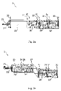
Figure 2a shows a torrefaction arrangement having a biomass inlet (21)
wherein the biomass is introduced in the torrefaction arrangement by means of
a
feeding screw (22). The biomass is dried in a drying zone (23) ) wherein heat
is
supplied to the drying zone (23) by means of a heating media (e.g. hot gases)
through a drying zone heating media inlet (24) and wherein the heating media
leaves
the drying zone through the drying zone heating media outlet (25). Dried
biomass is
transported through the drying zone (23) at a speed regulated by the feeding
speed
in the biomass inlet (21) and enters the heating zone (26) where the
temperature of
the biomass is elevated to a temperature near the desired torrefaction
temperature.
The heat is supplied to the heating zone (26) by means of a heating media
through a
heating zone heating media inlet (27) which leaves the heating zone through a
heating zone heating media outlet (28). The heated material enters a first
torrefaction
zone (29) in which the temperature can be controlled by introducing heating
media
and/or cooling media in the first torrefaction zone heating/cooling media
inlet (30)
wherein said heating/cooling media exits the first torrefaction zone through
the
torrefaction zone heating/cooling media outlets (31). The biomass thereafter
enters a
second torrefaction zone (32) heating/cooling media can be supplied to the
second
torrefaction zone via the torrefaction zone cooling media inlet (33) and said
heating/cooling media exits the torrefaction zone via a torrefaction zone
cooling
media outlet (34). The material transport in the heating zone (26) and
torrefaction
CA 02834434 2013-10-25
WO 2012/158112 PCT/SE2012/050527
zones (29, 32) is driven by a common transport screw which is attached to a
drum
enclosing the heating zone (26) and torrefaction zones (29, 32).
Figure 2b shows a torrefaction reactor having a biomass inlet (21) wherein the
biomass is introduced in the torrefaction arrangement by means of a feeding
screw
(22). The biomass is dried in a drying zone (23) wherein heat is supplied to
the drying
zone (23) by means of a heating media (e.g. hot gases) through a drying zone
heating media inlet (24) and wherein the heating media leaves the drying zone
through the drying zone heating media outlet (25). Dried biomass is
transported
through the drying zone (23) at a speed regulated by the feeding speed in the
biomass inlet (21) and enter the heating zone (26) where the temperature of
the
biomass is elevated to a temperature near the desired torrefaction
temperature. The
heat is supplied to the heating zone (26) by means of a heating media through
a
heating zone heating media inlet (27) which leaves the heating zone through a
heating zone heating media outlet (28). The transport of the biomass in the
heating
zone (26) is mediated by a heating zone transport screw which is fixed to the
inner
wall of a drum enclosing the heating zone (26). The material transport in the
heating
zone is controlled by the rotational speed of said drum and the biomass exits
the
heating zone through a connecting zone and enters a first torrefaction zone
(29) and
thereafter a second torrrefaction zone (32). The temperature in the
torrefaction zone
can be controlled by introducing heating media and/or cooling media in the
torrefaction zone heating/cooling media inlets (30, 33) wherein said
heating/cooling
media exits the torrefaction zone through the torrefaction zone
heating/cooling media
outlets (31, 34). The biomass transport in the first torrefaction zone (29)
and second
torrefaction zone (32) is driven by a common transport screw which is attached
to a
drum enclosing the first torrefaction zone (29) and second torrefaction zone
(32). The
material transport in the torrefaction zones (29, 32) is controlled by
rotational speed
of said drum can be rotated independently of the drum enclosing the heating
zone.
Hence the material transport in the torrefaction zone can be controlled
independently
of the material transport in the heating zone.
Figure 3 and 4 shows typical temperatures of the biomass in the different
zones in
the torrefaction arrangement disclosed in figures 2a and 2b, wherein the
torrefaction
CA 02834434 2013-10-25
WO 2012/158112 PCT/SE2012/050527
11
arrangement is connected to the arrangement for cooling torrefied material
described
in figure lb, in a manner described in figure la. Zone 1 represents the drying
zone
(2), zone 2 represents the heating zone (26), zone 3 represents the first
torrefaction
zone (29) and zone 4 represents the second torrefaction zone (32). In the
drying
zone (23) the biomass is dried, typically to a water content of 2-10 A (w/w)
and the
temperature is elevated to about 100 C. In the heating zone (26), the
temperature of
the material is elevated to close to the desired torrefaction temperature,
which in this
example is 350 C. In the torrefaction zones the temperature is kept virtually
constant
at the desired torrefaction temperature for a time corresponding to the
desired
torrefaction time. The cooling zone represents the arrangement for cooling
torrefied
material described in figure lb. The arrow indicates the initial quench-
cooling in the
water application device (3) and thereafter the torrefied material is cooled
to a
temperature below 100 C in the cooling device (4) for further cooling the
torrefied
material.
REFERENCES
[1] M. J Prins et al. More efficient biomass gasification via torrefaction.
Energy 2006,
31, (15), 3458-3470.
[2] P. C. A. Bergman et al. Torrefaction for Entrained
Flow Gasification of Biomass; Report C--05-067;
Energy Research Centre of The Netherlands (ECN):
Petten, The Netherlands, July 2005;
[3] K. Fl6kansson et al. Torrefaction and gasification of
hydrolysis residue. 16th European biomass conference
and exhibition, Valencia, Spain. ETAFlorence, 2008.
[4] A. Nordin, L. Pommer, I. Olofsson, K. Fl6kansson, M.
Nordwaeger, S. Wiklund LindstrOm, M. BrostOm, T.
Lestander, H. Orberg, G. Kalon, Swedish
Torrefaction R&D program. First Annual Report
2009-12-18 (2009).