Note : Les descriptions sont présentées dans la langue officielle dans laquelle elles ont été soumises.
CA 02835793 2013-12-03
DOUBLE ROTOR STEPPING MOTOR
The invention lies in the field of precision mechanical actuators. It
relates to a high precision stepping motor and can notably be used in the
actuating mechanisms of artificial satellites.
Artificial satellites generally require numerous actuating devices.
These devices may notably serve to deploy panels from a storage
configuration to a deployed configuration, to orient pointing mechanisms in
various directions, or to actuate elements of optical instruments such as
mirrors. Generally, the context of space imposes constraints in terms of
power consumption, reliability, weight and size. In addition, actuating
devices
often have to have high precision, that is to say a low angular resolution in
the case of rotary motors. Stepping motors are commonly used as
mechanical actuators for aerospace applications. Specifically, this type of
motor has a number of advantages, such as low friction, a possibility of
holding position without consuming power, and simplicity of control. In
particular, no automatic control is necessary to hold a particular position.
Stepping motors also have low angular resolution, which can reach several
tenths of a degree. However, a decrease in the angular resolution is
accompanied by an increase in the size and the mass of the motor. In
addition, finer angular resolutions may be necessary. One solution consists in
adding a mechanical reducing gear at the output of the stepping motor.
However, the introduction of a reducing gear involves a decrease in the
energy efficiency on account of the friction which it entails, and an increase
in
the weight and size. Another solution consists in the microstep control of the
stepping motor. This solution requires more expensive electronics and does
not make it possible to maintain a holding torque without a power supply.
One aim of the invention is notably to remedy all or some of the
abovementioned drawbacks by proposing a stepping motor that affords a
very low angular resolution while having a simple mechanical design and
simple electronic control, a limited size, and a possibility of holding
position
without consuming power. To this end, the subject of the invention is a
CA 02835793 2013-12-03
2
double rotor stepping motor having a differential movement. More
specifically, the subject of the invention is a stepping motor comprising:
= a stator comprising N stator contacts, where N is an integer greater
than or equal to three,
= a first rotor which is able to move with respect to the stator about an
axis, the first rotor comprising a first set of teeth distributed at a first
pitch pi,
and a second set of teeth distributed at a second pitch p2, and
= a second rotor which is able to move with respect to the first rotor
about the axis, the second rotor comprising N rotor contacts,
the N stator contacts comprising a plurality a of teeth distributed at the
pitch
pi, where a is an integer, the N stator contacts being distributed on the
stator
at a third pitch equal to pi(a+1/N), the teeth of the first set being able to
be
aligned individually with one of the stator contacts, the passage from one
alignment to a consecutive alignment causing the first rotor to move in a
first
direction with respect to the stator by the pitch pi/N,
the N rotor contacts comprising a plurality b of teeth distributed at the
pitch
p2, where b is an integer, the N rotor contacts being distributed on the
second
rotor at a fourth pitch equal to p2(b+1/N) and being able to be aligned
individually with one of the teeth of the second set, the passage from one
alignment to a consecutive alignment causing the second rotor to move in a
second direction, opposite to the first direction, with respect to the first
rotor
by the pitch p2/N.
According to one particular embodiment, the movements between
the stator, the first rotor and the second rotor are rotational movements
about
the axis.
Each stator contact may comprise a first ring portion, an internal
surface of which is toothed with the pitch pi, the teeth of the ring portion
being able to be aligned with teeth of the first set of the first rotor. Each
stator
contact may also comprise a second ring portion, an internal surface of which
is toothed with the pitch pi, the second ring portion being disposed
symmetrically about the axis with respect to the first ring portion, the teeth
of
the second ring portion being able to be aligned with teeth of the first set
of
the first rotor. The first rotor and the second rotor may thus each have N
CA 02835793 2013-12-03
3
concentric rings distributed along the axis and electromagnetically isolated
from one another, the first and second ring portions of each stator contact
being aligned with one of the rings of the first rotor and with one of the
rings
of the second rotor so as to allow a magnetic field to flow between the first
ring portion and the second ring portion.
According to one particular embodiment, the first rotor comprises
two parts that rotate as one about the axis, each part having N concentric
rings distributed along the axis and electromagnetically isolated from one
another, an external surface of each ring comprising teeth distributed at the
pitch pi and aligned between the various rings, an internal surface of each
ring comprising teeth distributed at the pitch p2 and aligned between the
various rings, the second rotor comprising two parts that rotate as one about
the axis, each part of the second rotor having N concentric rings distributed
along the axis and electromagnetically isolated from one another, an external
surface of each ring comprising teeth distributed at the pitch p2 and offset
with respect to the teeth of the other rings by the pitch p'2, each ring of
the
first rotor being aligned with one of the rings of the second rotor.
Moreover, each stator contact may comprise four concentric ring
portions, each ring portion being toothed with the pitch pi, for each stator
contact, a first ring portion and a second ring portion being disposed
symmetrically about the axis and cooperating with one of the rings of the
first
part of the first rotor and with one of the rings of the first part of the
second
rotor, a third ring portion and a fourth ring portion being disposed
symmetrically about the axis and cooperating with one of the rings of the
second part of the first rotor and with one of the rings of the second part of
the second rotor.
The invention has notably the advantage that it allows full pitch
control of the stepping motor, with said stepping motor having a very small
angular movement between the second rotor and the stator between two
successive power supply phases.
CA 02835793 2013-12-03
4
The invention will be better understood and further advantages will
become apparent from reading the following description which is given with
reference to the attached drawings, in which:
- Figure 1 shows, in the form of a simplified block diagram, a first
example of a stepping motor according to the invention;
- Figures 2 to 6 illustrate the operation of the stepping motor
from Figure 1 during various power supply phases;
- Figure 7 shows a second example of a stepping motor
according to the invention;
- Figures 8 and 9 show a perspective view and a sectional view,
respectively, of a stator of the stepping motor from Figure 7;
- Figure 10 shows a part of an intermediate rotor of the stepping
motor from Figure 7;
- Figure 11 shows a part of a central rotor of the stepping motor
from Figure 7;
- Figure 12 illustrates a longitudinal sectional view of the
operation of the stepping motor from Figure 7.
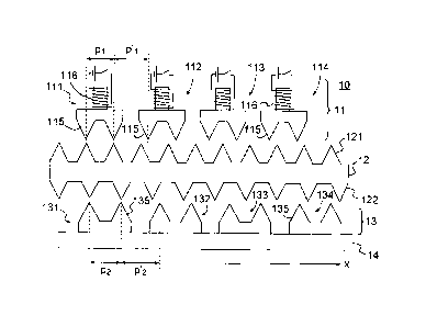
Figure 1 shows, in the form of a simplified block diagram, a first
example of a stepping motor according to the invention. The motor is shown
here in the form of a linear motor. However, it may also be a rotary motor in
a
flat development. The stepping motor 10 shown in Figure 1 comprises a
stator 11, a first rotor 12 and a second rotor 13 having a permanent magnet
14. The stator 11 has four stator contacts 111 to 114. Each stator contact
111-114 comprises two teeth 115 which are spaced apart from one another
by a pitch pl, and a coil 116 that can be supplied with an electric current in
order to create an electromagnetic field. The stator contacts 111-114 are
distributed on the stator 11 at a pitch pl(2+1/N). More specifically, the
stator
contacts are disposed such that one of the teeth 115 of a stator contact 111-
114 is located at a distance p'i from a contiguous stator contact. The pitch
p'i
is determined as a function of the pitch pl and the number N of stator
contacts. It is equal to (1+1/N). pi or, in the example of Figure 1,
(1+1/4).pi.
The first rotor 12, also known as the intermediate rotor, is in sliding
connection with respect to the stator 11 along an axis X (or in pivoting
connection about an axis orthogonal to the axis X in the case of a rotary
CA 02835793 2013-12-03
motor). The sliding connection should be understood broadly, that is to say
that the connection must comprise at least one degree of freedom in
translation along the axis X. The intermediate rotor 12 comprises a first set
of
teeth 121 distributed at the pitch pi and positioned opposite the teeth 115 of
5 the stator contacts 111-114. On account of the difference between the
pitches pi and p'1, it is not possible for the teeth 115 of all of the stator
contacts 111-114 to be aligned simultaneously with the teeth 121 of the
intermediate rotor 12. For each step of the motor, two teeth 121 are aligned
with the teeth 115 of one of the stator contacts 111-114. The intermediate
rotor 12 also comprises a second set of teeth 122 distributed at a pitch p2
which is different from the pitch pi. The second rotor 13, also known as the
central rotor, is in sliding connection with respect to the intermediate rotor
12
along the axis X (or in pivoting connection in the case of a rotary motor). It
is
thus also in sliding connection with respect to the stator 11. The central
rotor
13 comprises four sets 131 to 134 of teeth 135, known as rotor contacts, by
analogy with the stator contacts 111-114. Generally, the central rotor 13
comprises N rotor contacts, or as many rotor contacts as there are stator
contacts. Each rotor contact 131-134 comprises two teeth 135 that are
spaced apart from one another by the pitch p2. The rotor contacts 131-134
are distributed at a pitch p2(2+1/N). More specifically, the rotor contacts
are
disposed such that one of the teeth 135 of a rotor contact 131-134 is located
at a distance p'2 from a contiguous rotor contact. The pitch p'2 is determined
as a function of the pitch p2 and of the number N of rotor contacts and stator
contacts. It is equal to (1+1/N).p2 or, in the example of Figure 1,
(1+1/4).p2.
On account of the difference between the pitches p2 and p'2, it is not
possible
for the teeth 135 of all of the rotor contacts 131-134 to be aligned
simultaneously with the teeth 122 of the intermediate rotor 12. For each step
of the motor, two teeth 122 are aligned with the teeth 135 of one of the rotor
contacts 131-134. The permanent magnet 14 is attached to the central rotor
13 so as to create or increase the flow of the magnetic current between the
stator contacts 111-114 and the rotor contacts 131-134.
Figures 2 to 6 illustrate the operation of the stepping motor 10
schematically shown in Figure 1 during the successive power supply phases
thereof. A phase corresponds to a period of time during which a coil 116 of
CA 02835793 2013-12-03
6
one of the stator contacts 111-114 is supplied with power. The coil itself may
also be known as a "phase". During each phase, the intermediate rotor 12
and the central rotor 13 are positioned so as to minimize the reluctance
between one of the stator contacts 111-114 and the corresponding rotor
contact 131-134. Figure 2 shows the respective positions of the stator 11, the
intermediate rotor 12 and the central rotor 13 during a first phase,
specifically
when the coil 116 of the stator contact 111 is supplied with power. In order
to
minimize the reluctance between the stator contact 111 and the rotor contact
131, two teeth 121 of the intermediate rotor 12 are aligned with the teeth 115
of the stator contact 111, and two teeth 122 of the intermediate rotor 12 are
aligned with the teeth 135 of the rotor contact 131. The magnetic field 20
established between the stator contact 111 and the rotor contact 131 is thus
at a maximum.
Figure 3 shows the stepping motor 10 during the second phase,
that is to say when the coil 116 of the second stator contact 112 is supplied
with power. The positions of the intermediate rotor 12 and of the central
rotor
13 during the first phase are shown by dashed lines. In order to minimize the
reluctance between the stator contact 112 and the rotor contact 132, two
teeth 121 of the intermediate rotor 12 are aligned with the teeth 115 of the
stator contact 112, and two teeth 122 of the intermediate rotor 12 are aligned
with the teeth 135 of the rotor contact 132. Conventionally, the passage from
the first alignment between the teeth 115 of the stator contact 111 and the
teeth 121 of the intermediate rotor 12, to the second alignment between the
teeth 115 of the stator contact 112 and the teeth 121 of the intermediate
rotor
12 causes the intermediate rotor 12 to move with respect to the stator 11 by
a distance di equal to pi/N, or in this case p1/4. Analogously, the passage
from the first alignment between the teeth 122 of the intermediate rotor 12
and the teeth 135 of the rotor contact 131, to the second alignment between
the teeth 122 of the intermediate rotor 12 and the teeth 135 of the rotor
contact 132 causes the central rotor 13 to move with respect to the
intermediate rotor 12 by a distance d2 equal to p2/N, or in this case p2/4. In
as
much as the difference between the pitches pi and p2 is relatively small, the
intermediate rotor 12 is driven in a first direction Si and the central rotor
13 is
driven in a second direction S2, opposite to the first direction. Thus, the
CA 02835793 2013-12-03
7
resultant movement of the central rotor 13 with respect to the stator 11 is
less
than each of the two relative movements. The distance d3 covered by the
central rotor 13 with respect to the stator 11 is equal to the distance (d2-
di),
that is to say (p2-pi )/N. It follows that the distance d3 may be chosen to be
as
small as desired by choosing appropriate values of the pitches pi and p2.
Figure 4 shows the stepping motor 10 during the third phase, that
is to say when the coil 116 of the third stator contact 113 is supplied with
power. The intermediate rotor 12 and the central rotor 13 are again shown by
way of dashed lines in the positions which they occupied during the first
phase. During this third phase, it is the teeth 115 of the stator contact 113
which are aligned with teeth 121 of the intermediate rotor 12, and it is the
teeth 135 of the rotor contact 133 which are aligned with teeth 122 of the
intermediate rotor 12. The passage from the alignments of the second phase
to the alignments of the third phase causes the intermediate rotor 12 to move
again with respect to the stator 11 by the distance di and in the direction
Si,
and the central rotor 13 to move again with respect to the intermediate rotor
12 by the distance d2 and in the direction S2. The central rotor 13 has thus
undergone a movement equal to 2.(d2-di) since the first phase.
Figure 5 shows the stepping motor 10 during the fourth phase, that
is to say when the coil 116 of the fourth stator contact 114 is supplied with
power. In this phase, the teeth 115 of the stator contact 114 are aligned with
teeth 121 of the intermediate rotor 12, and the teeth 135 of the rotor contact
134 are aligned with teeth 122 of the intermediate rotor 12. The passage
from the alignments of the third phase to the alignments of the fourth phase
causes the intermediate rotor 12 to move again with respect to the stator 11
by the distance di and in the direction Si, and the central rotor 13 to move
again with respect to the intermediate rotor 12 by the distance d2 and in the
direction S2. The central rotor 13 has thus undergone a movement equal to
3.(d2-dl) since the first phase.
Figure 6 shows the stepping motor 10 during the fifth phase. This
phase corresponds in fact to the first phase, in which the coil of the first
stator
contact 111 is supplied with power. The same alignments as those of the first
CA 02835793 2013-12-03
8
phase are obtained. The successive passages from the first to the fifth phase
have thus caused the intermediate rotor 12 to move with respect to the stator
11 by the distance pi ¨ or 4.di ¨ and in the direction Si, and the central
rotor
13 to move with respect to the intermediate rotor 12 by the distance p2 ¨ or
4.d2 ¨ and in the direction S2. Consequently, the movement of the central
rotor 13 with respect to the stator 11 is equal to p2-pi.
The exemplary embodiment of the stepping motor in Figure 1 may
be generalized. In particular, as indicated above, the invention may be
io applied to rotary stepping motors. In such a case, the movements of the
rotors are rotary movements, and the pitches in question are angular pitches.
Furthermore, a number N of rotor contacts and stator contacts equal to 4 was
considered. However, the number N may have any integer value greater than
or equal to 3. Generally, each stator contact and each rotor contact may
16 comprise one or more teeth. With a being an integer representing the
number
of teeth of each stator contact, the stator contacts are distributed on the
stator at a pitch equal to pi(a+1/N). Similarly, with b being an integer
representing the number of teeth of each rotor contact, the rotor contacts are
distributed on the rotor at a pitch equal to p2(b+1/N). Preferably, the rotor
20 contacts and stator contacts comprise the same number of teeth. When a
contact comprises a plurality of teeth, these teeth are distributed at the
pitch
pi or p2, depending on whether it is a stator contact or rotor contact,
respectively. Each tooth positioned at the end of the plurality of teeth of a
stator contact must be at the distance 13'1 from one of the teeth of a
25 consecutive stator contact. Similarly, each tooth positioned at the end of
the
plurality of teeth of a rotor contact must be at the distance p'2 from one of
the
teeth of a consecutive rotor contact. The pitches p'i and p'2 were indicated
as
being equal to (1+1/N).pi and (1+1/N).p2, respectively. However, on account
of the periodicity of the teeth of the intermediate rotor and of the central
rotor,
30 these pitches may also be equal to pi/N and p2/N, respectively. The teeth
of
the stator, of the intermediate rotor and of the central rotor were shown
schematically in the form of triangles in Figures 1 to 6. However, any other
shape of tooth may be used within the scope of the invention. More
generally, the teeth may be replaced by any means that is able to generate
35 positions having a reluctance less than that of the other positions. In
CA 02835793 2013-12-03
9
particular, materials having different electromagnetic properties may be used.
By way of example, the pitch p2 may be equal to 1.1 times the pitch pl. The
difference between the pitches pi and p2 may be adapted depending on the
desired angular resolution between the stator and the central rotor.
Figure 7 shows a second exemplary embodiment of a stepping
motor according to the invention. In this case, it is a rotary stepping motor
having variable reluctance and staged rotors. The stepping motor 30
comprises a stator 31, an intermediate rotor 32 and a central rotor 33 having
a permanent magnet 34. The permanent magnet 34 is secured to the central
rotor 33. The rotors 32 and 33 are in pivoting connection with respect to the
stator 31 about an axis Y.
Figures 8 and 9 show the stator 31 of the motor 30 from Figure 7
in a perspective view and in a sectional view along the axis Y, respectively.
The stator 31 comprises four stator contacts 311, 312, 313 and 314. Each
stator contact 311-314 has four ring portions 311A-311D, 312A-312D, 313A-
313D and 314A-314D, respectively. These ring portions are generically
denoted 31A-31D. Each ring portion 31C is offset in translation along the axis
Y from the corresponding ring portion 31A. The ring portions 31B and 31D
are positioned facing each ring portion 31A and 31C, respectively. Each ring
portion is toothed at one and the same pitch pi. The teeth of the ring portion
312A are angularly offset from the teeth of the ring portion 311A by a pitch
pi,. The pitch p'l is equal to 1/4.pl. More generally, the angular offset is
equal
to 1/N.pi, where N is the number of stator contacts. Similarly, the teeth of
the
ring portions 313A and 314A are angularly offset from the teeth of the ring
portions 312A and 313A, respectively, by the pitch p'i. The same goes for the
ring portions 311B-314B, 311C-314C, and 311D-314D. The teeth of the ring
portions 31A are aligned with the teeth of the respective ring portions 31C,
and the teeth of the ring portions 31B are aligned with the teeth of the ring
portions 31D. The stator also comprises eight coils 316 which are supplied
with power in pairs. A first coil 316 makes it possible to supply power to the
ring portions 311A and 311C. A second coil 316 makes it possible to supply
power to the ring portions 311B and 311D. Analogously, the six other coils
make it possible to supply power individually to the ring portions 312A and
CA 02835793 2013-12-03
312C, 312B and 312D, 313A and 3130, 313B and 313D, 314A and 314C,
and 314B and 314D.
Figure 10 shows a perspective view of a part 32A of the
5 intermediate rotor 32. The part 32A comprises four concentric rings, known
as stages 321 to 324, distributed along the axis Y and rotating as one about
the axis Y. The number of stages of the part 32A is equal to the number N of
stator contacts. The stages 321-324 are electromagnetically isolated from
one another by spacers 325. The external surface of each ring 321-324
10 carries a set of teeth 326 distributed at the pitch pi. The teeth 326 of
each
stage 321-324 are aligned with those of the other stages. The internal
surface of each ring 321-324 carries a set of teeth 327 distributed at the
pitch
p2. The teeth 327 of each stage 321-324 are aligned with those of the other
stages. The intermediate rotor 32 comprises two parts 32A and 32B which
rotate as one about the axis Y. The part 32B, not shown, is identical to the
part 32A. The part 32A is aligned with the ring portions 31A and 31B, and the
part 32B is aligned with the ring portions 31C and 31D. More specifically, the
stages 321-324 of the part 32A are respectively positioned opposite the ring
portions 311A and 311B, 312A and 312B, 313A and 313B, and 314A and
314B. The stages 321-324 of the part 32B are respectively positioned
opposite the ring portions 311C and 311D, 3120 and 312D, 3130 and 313D,
and 314C and 3140. The intermediate rotor 32 is dimensioned such that the
teeth 326 can cooperate with the teeth of the ring portions 31A-31D.
Figure 11 shows a perspective view of a part 33A of the central
rotor 33. The part 33A comprises four concentric rings, known as stages 331
to 334, distributed along the axis Y and rotating as one about the axis Y.
More generally, the part 33A comprises as many stages as the number N of
stator contacts. The stages 331-334 are electromagnetically isolated from
one another by spacers 335. The external surface of each ring 331-334
carries a set of teeth 336 distributed at the pitch p2. The teeth 336 of each
stage 331-334 are offset by a pitch p'2, equal to 1/4.p2 or, more generally,
1/N.p2. The central rotor comprises two parts 33A and 33B that rotate as one
about the axis Y. The part 33B, not shown, is identical to the part 33A. The
part 33A is aligned with the part 32A of the intermediate rotor 32, and the
part
CA 02835793 2013-12-03
11
33B is aligned with the part 32B of the intermediate rotor 32. The central
rotor
33 is dimensioned such that the teeth 336 can cooperate with the teeth 327
of the intermediate rotor 32. The stepping motor 30 thus operates
analogously to the stepping motor 10 illustrated in Figures 1 to 6.
Figure 12 illustrates a longitudinal sectional view along the axis Y
of the operation of the stepping motor 30 in a third power supply phase. In
this phase, the teeth of the ring portions 313A, 313B, 313C and 3130 are
aligned with the teeth 326 of the rings 323 of the two parts 32A and 32B of
the intermediate rotor 32. Moreover, the teeth 327 of these same rings 323
are aligned with the teeth 336 of the rings 333 of the two parts 33A and 33B
of the central rotor 33. Field lines 41 and 42 can thus flow between the
stator
31, the intermediate rotor 32, the central rotor 33 and the permanent magnet
34.
By studying Figure 12, it will be understood that the stepping
motor 30 could be modified without departing from the scope of the invention.
For example, the intermediate rotor 32 and the central rotor 33 may have
only a single part of N stages, and the stator 31 may have only the eight ring
portions 31A and 31B. The field lines are thus established between the ring
portions 31A and 31B. By contrast, it is possible for the stepping motor only
to have the ring portions 31A and 31C, or 31B and 31D. The two
intermediate rotor 32 and central rotor 33 parts are thus necessary.
Furthermore, the number N of stages and of stator contacts may have any
integer value greater than or equal to 3. Moreover, the shapes of the teeth
may differ from those shown in Figures 7 to 11.