Note : Les descriptions sont présentées dans la langue officielle dans laquelle elles ont été soumises.
CA 02836019 2013-12-09
37085-0049001
MAGNETICALLY TRACKED SENSOR
TECHNICAL FIELD
This disclosure relates to a magnetically tracked sensor.
BACKGROUND
Magnetic tracking of instruments with respect to imaged anatomy is widely
employed in medical practice. Imaging systems that are enhanced with magnetic
tracking
may be used to track and display position and orientation of a diagnostic or
therapeutic
instrument relative to the imaging plane. They can help the clinician guide
the instrument
to a chosen target with reduced error compared to an unguided instrument.
Furthermore,
the visual representation of the tracked instrument is not necessarily
constrained to the
ultrasound imaging plane, thus enabling the clinician with more freedom of
motion.
For magnetic tracking of an instrument, an electromagnetic sensor can be
included in a location of the instrument. Electromagnetic sensors can be
electromagnetic
coils that surround or are close to the objects whose location is being
tracked. If an
instrument with an included sensor is placed within a varying electromagnetic
field, a
voltage can be generated in the electromagnetic sensor. This generated voltage
can be
used to determine and track the locations and relative positioning of the
instrument within
the electromagnetic field. An ultrasound system enhanced with magnetic
tracking of
sensors can display a 3-dimensional merger of ultrasound generated anatomical
features
and the visual representation of the instrument position and orientation.
SUMMARY
In one aspect, in general, a magnetic field sensor assembly includes a hollow
core
comprising a ferromagnetic material, the hollow core having a proximal end and
a distal
end, conductive material disposed around the hollow core and forming at least
one turn of
a coil, the coil comprising at least one start terminal and at least one
finish terminal, at
least first and second lead wires passing through the center of the hollow
core, wherein
the first lead wire is connected to the start terminal to form a first
termination and
wherein the second lead wire is connected to the finish terminal to form a
second
1
CA 02836019 2013-12-09
37085-0049001
termination, and wherein the first and second lead wires are capable of
carrying electrical
signals from the coil to a magnetic position measurement system for
determining a sensor
position.
Implementations may include one or more of the following features. The hollow
core is a hollow cylindrical core. The first and second terminations are
positioned within
the hollow core. The first and second terminations are positioned within the
distal end of
the hollow core. The first and second terminations are positioned within the
proximal end
of the hollow core. The first and second lead wires and the first and second
terminations
are permanently fixed within the hollow core. The hollow core includes ferrite
material.
The hollow core includes magnetic material. The hollow core includes hardened
austenitic stainless steel material. The conductive material includes magnetic
wire. The
conductive material includes patterned conductive material deposited onto a
dielectric
material. The first and second terminations are formed by soldering, welding
or joining
by a conductive adhesive.
In another aspect, in general, a method includes providing a hollow core
= comprising ferromagnetic material, the hollow core having a proximal end
and a distal
end, disposing conductive material around the hollow core and forming at least
one turn
of a coil, the coil comprising at least one start terminal and at least one
finish terminal,
passing at least first and second lead wires through the center of the hollow
core,
connecting the first lead wire to the start terminal to form a first
termination, connecting
the second lead wire to the finish terminal to form a second termination,
wherein the first
and second lead wires are capable of carrying electrical signals from the coil
to a
magnetic position measurement system for determining a sensor position.
Implementations may include one or more of the following features. The hollow
core is a hollow cylindrical core. The first and second terminations are
positioned within
the hollow core. The first and second terminations are positioned within the
distal end of
the hollow core. The first and second terminations are positioned within the
proximal end
of the hollow core. The method includes permanently fixing the first and
second lead
wires and the first and second terminations within the hollow core. The hollow
core
includes ferrite material. The hollow core includes magnetic material. The
hollow core
includes hardened austenitic stainless steel material. The conductive material
includes
2
CA 02836019 2013-12-09
=
37085-0049001
magnetic wire. The conductive material includes patterned conductive material
deposited
onto a dielectric material. The first and second terminations are formed via
soldering,
welding or joining via a conductive adhesive.
In a further aspect, in general, an electromagnetic position measurement
system
includes a magnetic field sensor assembly configured to measure at least 3
degrees of
freedom position and angular orientation data when placed within an
electromagnetic
field and including a hollow core comprising a ferromagnetic material, the
hollow core
having a proximal end and a distal end, conductive material disposed around
the hollow
core and forming at least one turn of a coil, the coil comprising at least one
start terminal
and at least one finish terminal, and at least first and second lead wires
passing through
the center of the hollow core, wherein the first lead wire is connected to the
start terminal
to form a first termination and wherein the second lead wire is connected to
the finish
terminal to form a second termination, wherein the first and second
terminations are
positioned within the hollow core and wherein the first and second lead wires
are capable
of carrying electrical signals from the coil to the electromagnetic position
measurement
system for determining a sensor position.
Implementations may include one or more of the following features. The hollow
core is a hollow cylindrical core. The first and second terminations are
positioned within
the hollow core.
Two or more of the features described in this disclosure, including those
described in this summary section, may be combined to form implementations not
specifically described herein.
The details of one or more implementations are set forth in the accompanying
drawings and the descriptions below. Other features, objects, and advantages
will be
apparent from the description and drawings, and from the claims.
DESCRIPTION OF DRAWINGS
FIG. 1 illustrates an ultrasound imaging system enhanced with magnetic
instrument tracking.
3
CA 02836019 2013-12-09
37085-0049001
FIG. 2A-FIG. 2C illustrate methods of attachment and encapsulation of the
sensor
element.
FIG. 3A-FIG. 3C depict cross-sectional views of a hollow ferromagnetic core
sensor.
FIG. 4A-FIG. 4C depict cross-sectional views of another implementation of a
hollow ferromagnetic core sensor.
FIG. 5A-FIG. 5C depict cross-sectional views of yet another implementation of
a
hollow ferromagnetic core sensor.
Like reference symbols in the various drawings indicate like elements.
DETAILED DESCRIPTION
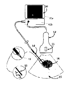
Referring to FIG. 1, imaging tools, such as ultrasound system 10, are used to
image detailed anatomical features in a spatial slice (or imaging plane) 16.
Ultrasound
system 10 includes a hand-held probe 12, a display 10a and electronics 10b.
For magnetic
tracking of an instrument 14 with ultrasound system 10, electromagnetic
sensors 11 and
13 are included in the hand-held ultrasound probe 12 and in a location of
instrument 14,
respectively. Sensors 11 and 13 can be electromagnetic coils that surround or
are close to
the objects whose location is being tracked. In the example of FIG. 1,
instrument 14 is a
needle assembly and sensor 13 is close to the needle tip 19. When sensor 13 is
placed
within a varying electromagnetic field, a voltage is generated in the
electromagnetic
sensor 13. Similarly, when hand-held ultrasound probe 12 with the embedded
sensor 11
is placed within the varying electromagnetic field, a voltage is generated in
the
electromagnetic sensor 11. These generated voltages in sensors 11, 13 are used
to
determine and track the locations and relative positioning of ultrasound probe
12 and
needle tip 19, respectively, within the electromagnetic field. Ultrasound
system 10,
enhanced with magnetic tracking of sensors 11 and 13, displays the 3-
dimensional
merger of ultrasound generated anatomical features 16 in area of interest 15
and the
visual representation of the instrument's 14 position and orientation.
FIGS. 2A- 2C show two methods of constructing five degree-of-freedom
magnetic sensor assemblies. Magnet wire 32 is wound around ferromagnetic core
30. In
FIG. 2A, lead wire pair 31 is connected to magnet wires 32 at each of two
termination
4
CA 02836019 2013-12-09
=
37085-0049001
(winding start and finish) points 33a, 33b. The finished diameter 13b of
sensor 13 is
usually in the range of 1 mm, and may be as small as 0.3mm, so the components,
especially the connection points 33a, 33b, are extremely fragile and difficult
to
manipulate without damaging them. These construction methods result in a very
fragile
zone between termination points 33a, 33b and core 30, as coil wire 32 is
typically .0005"
in diameter and is thus easily damaged or broken. In certain cases, it is
advantageous to
join one conductor of lead wire 31 directly to core 30 by soldering or
adhesive methods
34, as shown in FIG. 2B. This allows the larger conductor of lead wire 31 to
support the
mechanical forces encountered by sensor 13 during assembly and use. This
joining
process has the disadvantage of requiring precise application and curing of
adhesive or
subjecting the coil assembly to soldering temperatures, which may damage the
insulation
if not done precisely. A second common method of addressing the fragility of
termination
area 33 is to place a tube 35 over the sensor 13, such that it encompasses
termination area
33 and provides mechanical support. The tube 35 with sensor 13 assembly is
then fill-
_
injected with adhesive. This tube must extend well beyond termination area 33
to provide
overlap between the lead wires and the tube, allowing area for the lap shear
adhesive joint
to form. This has the disadvantage of either increasing the rigid length 13a
of sensor 13
or requiring a shorter core, which will decrease the signal output of the
sensor and reduce
its useful range. The methods of adhesive injection require costly sensor-to-
tube
alignment fixturing and precise flow controllers. Also, the rigid nature of
tube 35 and the
extended lap shear area form a lever arm with the weak point at termination
area 33.
Great care must be taken during the assembly process not to break or damage
connection
wires 31 32 or termination points 33a, 33b when inserting them into tube 35.
Tube 35 is
commonly a metal material such as stainless steel or a plastic material such
as polyester,
depending on the desired properties of the finished product. When tube 35 is a
plastic
material, it must have enough wall thickness to prevent flexing of termination
area 33, as
the connections in this area are easily broken. Although tube 35 is commonly
filled with a
stress relieving adhesive, termination area 33 is still a weak stress point
and is prone to
breakage. Also, the termination of these sensors is exposed to the magnetic
field, which
the sensors are detecting. Since a single coil sensor cannot detect rotation
about its axis, it
must be assumed that the magnetic axis and physical axis of the coil are co-
linear. If the
5
CA 02836019 2013-12-09
37085-0049001
termination process results in an undesired out of plane loop 36 being formed.
This loop
36 may misalign the sensor's 13 magnetic axis from its physical axis. Such a
loop is in
fact very difficult to avoid in some construction methods as the conductors
are separated
in the termination area 33 to avoid short circuiting, and a relatively large
loop results
from this separation.
Referring to FIGS. 3A- 3C, ferromagnetic sensor 13 includes a twisted lead
wire
31 placed within a ferromagnetic hollow core 50. Coil wire 32 is wound around
the
ferromagnetic core 50 and the ends 32a, 32b are connected to the termination
ends 33a,
33b of the lead wire 31, which occurs at the opposite end of core 50, compared
to the
sensors shown in FIGS. 2A-2C. Adhesive coating 51 is applied after completing
termination connections 33a, 33b and is wicked into the space between core 50
and lead
wire 31, thus creating a secure bond along the inside surface of core 50.
Terminations
33a, 33b can be performed in close proximity to the end 50a of core 50 so as
to minimize
= the length of the sensor 13. Because the bonding surfaces between lead
wire 31 and coil
wire 32 are internal to core 50, strain relief area 52 can be zero length,
which is not
possible with other construction techniques. This allows the rigid portion of
the sensor to
be shorter without sacrificing the strength of the assembly, thus enabling
instruments
equipped with the sensor to navigate tortuous anatomy, such as blood vessels,
more
easily.
As was shown in FIG. 2A, in one sensor design, coil wire 32 and lead wire 31
are
sometimes deformed during the termination process. This deformation is
difficult to
avoid as lead wire 31 must be separated somewhat so that it can be joined to
coil wires 32
at termination 33 without creating a short circuit caused by the removal of
insulation in
the area of termination 33. Also, some bending and manipulation of coil wires
32 and
lead wires 31 is usually required. Due to these factors, a small undesired
parasitic loop 36
can be formed. This loop has an axis of maximum sensitivity which may differ
from the
physical axis of sensor 13. Shielding this loop's magnetic field can remove
the effect of
the loop on the sensor output.
Referring to FIGS. 4A- 4C, in a method of aligning the magnetic and physical
axes of sensor 13, terminations 33a, 33b are connected to coil wire ends 32a,
32b at the
distal end 50a of core 50 and then the connected termination points are
inserted into the
6
CA 02836019 2013-12-09
37085-0049001
distal end 50a of core 50 and pushed towards into the hollow core 50. Because
the
magnetic field inside of a ferromagnetic tube is attenuated, core 50 acts as a
magnetic
shield for undesired parasitic loops formed during the creation of
terminations 33a, 33b.
This has a benefit of improving the alignment of the magnetic and physical
axes of sensor
13. The alignment of the magnetic and physical axes of sensor 13 is notable
because
sensor 13 cannot detect angular rotation parallel to its magnetic axis, thus
if the magnetic
and physical axes of sensor 13 are not co-incident, imaging errors occur.
Therefore, if the
magnetic and physical axes are not aligned, sliding sensor 13 into a biopsy
needle such as
tubular instrument 14 causes errors in the displayed trajectory of instrument
14 with
respect to imaged anatomy 10. A calibration step may be employed to reduce
this
trajectory error, but this complicates the manufacturing process. Placing
terminations
33a, 33b inside of core 50 removes a major source of error for applications
requiring
accurate display of instrument trajectory without additional calibration
steps.
In certain applications, it may not be possible to gain access to the distal
end 50a
of hollow core 50. This is the case when sensor 13 is pre-molded into an
instrument with
only the proximal end 50b of core 50 exposed. In this case, referring to FIGS.
5A-5C,
terminations 33a, 33b are performed at the proximal end 50b of core 50. The
ends 32a,
32b of lead cable 31 are connected to terminations 33a, 33b and the connected
points are
inserted into proximal end 50b and pushed within the hollow core 50. Core 50
then acts
as a magnetic shield for terminations 33a, 33b, and the improvements in
imaging
accuracy are similar to those gained by shielding terminations 33a, 33b at the
distal end
50b of core 50.
FIG. 6 shows a flowchart 100 detailing steps for producing a magnetic field
sensor assembly, e.g., the magnetic field sensor assembly shown in FIGS. 3A-
3C. Step
102 includes providing a hollow core (e.g., a hollow cylindrical core)
comprising
ferromagnetic material. The hollow core has a proximal end and a distal end.
In some
implementations, the hollow core can include ferrite material. The hollow core
can also
include magnetic material. In some examples, the hollow core can include
hardened
austenitic stainless steel material. Step 104 includes disposing conductive
material around
the hollow core and forming at least one turn of a coil. The coil has at least
one start
terminal and at least one finish terminal. In some implementations, the
conductive
7
CA 02836019 2013-12-09
37085-0049001
material can include magnetic wire. In some implementations, the conductive
material
can include patterned conductive material deposited onto a dielectric
material. Step 106
includes passing first and second lead wires through the center of the hollow
core. Step
108 includes connecting the first lead wire to the start terminal to form a
first termination.
Step 110 includes connecting the second lead wire to the finish terminal to
form a second
termination. In some examples, the first and second terminations can be
positioned within
the distal end or the proximal end of the hollow core. In some
implementations, the first
and second lead wires and the first and second terminations can be permanently
fixed
within the hollow core. Step 112 includes optionally positioning the first and
second
terminations within the hollow core. The first and second lead wires can be
capable of
carrying electrical signals from the coil to a magnetic position measurement
system for
determining a sensor position.
The magnetic field sensor assembly described here tends to have a termination
area that is less fragile than other kinds of sensors. Various implementations
of the
assembly are possible. The ferromagnetic core can be made hollow, an example
being a
ferrite bead core. The lead wire can be passed through the center of the
hollow bead core,
and can be secured with an adhesive tack before performing the delicate
process of
connecting the fragile coil wires to the lead wire. The termination process
can be
performed at the distal end of the assembly. The application of adhesive can
be done on
the proximal end of the coil and is much simpler because capillary action will
pull the
adhesive into the center of the hollow core in a controllable manner.
In some examples, the sensor can be dipped in adhesive, whereby the adhesive
wicks into and around the sensor, securing any wires inside the core and
encapsulating
the sensor. The self fixturing nature of this process can allow the
termination process to
proceed without maintaining the coil assembly and lead wire in a fixed
location relative
to each other. Positioning terminations on the distal end or inside the sensor
core also
shortens the sensor for a given core length, as the lead wires are strain
relieved to the
inside of the core. A lever arm with the highest stress point coinciding with
the weakest
point over the termination area need not be used.
The termination can be performed at the distal or proximal end without first
securing the lead wire to the inside of the hollow sensor core. The
termination can be
8
CA 02836019 2013-12-09
=
37085-0049001
pushed or pulled into the hollow core before applying adhesive. In this
manner, the
termination area does not add to the length of the sensor, and the lead wire
can still be
securely fastened to the inside of the sensor core. In this configuration, the
parasitic loops
formed by the terminations are magnetically shielded by the hollow core and
the
magnetic axis of the sensor is better aligned with the physical axis.
The magnetic sensor may be movable within the instrument in order to enable
its
replacement with a therapeutic device after successful placement of the
instrument tip at
the target area. Furthermore, the magnetic sensor may be re-introduced for the
purpose of
navigating to another target. The magnetic sensor can be constructed so that
it can handle
this movement. Also, due to the curvilinear nature of many surgical tools and
of most
passages in the human body, the length of the magnetic sensor can be limited
while
maintaining its mechanical strength.
Other implementations not specifically described herein are also within the
scope of the following claims.
9