Note : Les descriptions sont présentées dans la langue officielle dans laquelle elles ont été soumises.
CA 02836841 2013-11-20
WO 2012/163723 PCT/EP2012/059447
MEDIUM VOLTAGE SWITCHGEAR
DESCRIPTION
The present invention relates to a medium voltage switchgear with improved
features,
and in particular to a medium voltage switchgear having a circuit breaker in
the so-called
withdrawable configuration. For the purposes of the present application the
term medium
voltage is referred to applications in the range from 1 kV up to some tens of
KV, for example
52 kV.
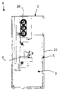
With reference to figure 1, a medium voltage switchgear 1 is well known in the
art and
it usually consists of a casing 2 which defines an internal volume 3 for
housing a circuit breaker
assembly 4 and, e.g., a bus-bar assembly 39, as well as other systems, such as
a feeder system
and possible auxiliary equipment.
The circuit breaker assembly 4 is normally positioned inside a circuit breaker
compartment, said circuit breaker assembly 4 being, in the so-called
withdrawable
configuration, movable between a service position, in which it is connected to
the bus-bar and
feeder systems, and a test/disconnected position in which it is isolated from
the bus-bar and
feeder systems. Depending on the application a grounding position is also
possible.
In practice, with reference to figure 1 the circuit breaker assembly 4 can be
moved from
the service position shown in said figure, to a test/disconnected position
and/or a grounding
position, by sliding said assembly 4 toward the right-hand side of the figure.
In order to do
that, the circuit breaker assembly 4 is normally positioned on a sliding frame
(not-shown)
actuated from the outside of the casing 2. The sliding frame and its operation
are well known
in the art and will not be described in details here. In order to carry out
the moving operation
of the circuit breaker, an opening 5 is normally present of the front panel 21
of the switchgear
1, so as to allow the insertion and extraction of an operating handle.
A first drawback of the known solutions is due to the fact that the opening 5
allows a
direct communication between the circuit breaker compartment and the outside
of the
switchgear 1, with safety concerns in case of faults, such as an internal arc.
Also, when the operating handle is inserted and the opening 5 is therefore
closed (i.e.
no direct communication between the inside and outside of the switchgear), a
sudden increase
of pressure inside the switchgear due to an internal fault may abruptly push
away the handle
with consequent safety concerns.
It is therefore an object of the present invention to provide a medium voltage
switchgear in which the above-mentioned drawbacks are avoided or at least
reduced.
1
CA 02836841 2013-11-20
WO 2012/163723 PCT/EP2012/059447
More in particular, it is an object of the present invention to provide medium
voltage
switchgear having a greater degree of safety with respect to the conventional
medium voltage
switchgear.
As a further object, the present invention is aimed at providing a medium
voltage
switchgear in which the insertion/withdrawing operation of the circuit breaker
can be carried
out in an always safe way.
A further object of the present invention is to provide a medium voltage
switchgear in
which the separation between the inside and outside is always maintained.
Another object of the present invention is to provide a medium voltage
switchgear
having a reduced number of mechanical parts.
Another object of the present invention is to provide a medium voltage
switchgear
having a withdrawing system of the circuit breaker with improved
functionality.
Still another object of the present invention is to provide a medium voltage
switchgear
with reduced manufacturing, installation and maintenance costs.
Thus, the present invention relates to a medium voltage switchgear which is
characterized in that it comprises a casing defining an internal volume for
housing at least a
circuit breaker assembly movable between at least two operative positions,
said casing
comprising a front panel provided with an opening for the insertion of an
operating handle for
actuating the movement of said circuit breaker assembly between said operative
positions, a
closing and retaining device being positioned in correspondence of said
opening and being
movable between a closed position when said operating handle is not inserted
and an open
position for allowing insertion of said operating handle, said closing and
retaining device
comprising locking means for retaining said operating handle in position when
inserted in said
opening.
In this way, it is possible to overcome some of the disadvantages and
drawbacks of the
circuit breaker of the known art.
In particular, the presence of a closing and retaining device allows to keep
the opening
always covered and protected, thereby always separating the circuit breaker
compartment from
the outside of the switchgear
Another important advantage derives form the fact that, as better explained in
the
following description, the operating handle, when inserted, is always locked
and maintained in
position by the closing and retaining device.
The medium voltage switchgear according to the invention preferably comprises
a
2
CA 02836841 2013-11-20
WO 2012/163723 PCT/EP2012/059447
closing and retaining device comprising elastic retaining means, e.g. springs
or equivalent
means, for keeping it in said closed position, and opening means for its
opening, said opening
means comprising, for example, a manually operated knob that can be actuated
by an operator.
In a preferred embodiment of the medium voltage switchgear according to the
invention, said closing and retaining device comprises a first and a second
plate respectively
provided with a first and a second hole axially aligned with said opening when
said closing and
retaining device is in the open position, said first and a second plate
covering and closing said
opening when said closing and retaining device is in the closed position.
In such a case, said first and a second plate are preferably hinged on a
common point,
e.g. on the front panel, and rotate in opposite directions when passing from
said closed to said
open position.
Preferably, said first and a second plate are substantially C-shaped and
comprises a first
and a second lateral portion extending form a central portion.
According to a possible embodiment of the medium voltage switchgear of the
invention, said first and a second plate respectively comprise a first and a
second actuating
surface extending therefrom and interacting with an actuating cam operatively
coupled with
said opening means. For instance, said first and second actuating surfaces can
be positioned on
the central portion of said first and a second plate which can be hinged on
said common point
in correspondence of said first lateral portion, while said first and second
hole can be
positioned on said second lateral portion of said first and second plate.
According to a possible embodiment of the medium voltage switchgear of the
invention, said locking means comprise a cutout portion on the periphery of
said first and
second hole for engaging and retaining said operating handle.
Further characteristics and advantages of the invention will emerge from the
description
of preferred, but not exclusive embodiments of a medium voltage switchgear
according to the
invention, non-limiting examples of which are provided in the attached
drawings, wherein:
Figure 1 is a schematic side view of a a medium voltage switchgear;
Figure 2 is a first view of a first embodiment of a closing and retaining
device used in a
medium voltage switchgear according to the invention, shown in a first, open,
position;
Figure 3 is a second view of the closing and retaining device of figure 1;
Figure 4 is a first view of a first embodiment of a closing and retaining
device used in a
medium voltage switchgear according to the invention, shown in a second,
closed, position;
Figure 5 shows the device of figure 2 with an operating handle inserted;
3
CA 02836841 2013-11-20
WO 2012/163723 PCT/EP2012/059447
Figure 6 shows the device of figure 3 with an operating handle inserted;
Figure 7 shows a second view of the device of figure 4 with an operating
handle
inserted and locked;
Figure 8 shows the device of figure 4 with an operating handle inserted and
locked.
With reference to the attached figures, a medium voltage switchgear according
to the
invention, designed with the reference number 1, comprises, in its more
general definition, a
casing 2 which defines an internal volume 3.
At least a circuit breaker assembly 4 is housed inside the internal volume 3,
said circuit
breaker assembly 4 being movable between at least two operative positions,
e.g. a
test/disconnected position and a service position in which it is connected to
the bus bar
assembly 39. Other operative positions, e.g. a grounding position, are also
possible.
To this purpose, the casing 2 normally comprises a front panel 21, e.g. a
door, provided
with an opening 5 for the insertion of an operating handle 8 which is used for
actuating the
movement of the circuit breaker assembly 4 between said operative positions.
With reference to figure 2-8, one of the characterizing features of the medium
voltage
switchgear according to the invention derives for the presence of a closing
and retaining device
6 which is positioned in correspondence of said opening 5.
In figures 2-8, for sake of clarity, the front panel 21 is not shown. Also,
figures 3, 4, 6,
and 8, show the side of the device 6 facing toward the outside of the
switchgear, i.e., the side
of the device positioned on the inside surface of the panel 21 and therefore
normally non
visible; figures 2, 5, and 7 show the side of the device 6 facing toward the
inside of the
switchgear, i.e. facing inside the circuit breaker compartment. Moreover, in
figures 2, 3, 5, and
6, the closing and retaining device 6 is shown in the open position, while in
figures 4 it is
shown in the closed position. Also, in figures 5 and 6 the operating handle is
inserted but not
locked, while in figure 7 and 8 the operating handle is inserted and locked
into place.
The device 6 is movable between a closed position (figs. 4) when said
operating handle
8 is not inserted and an open position (figs. 2, 3, 5, and 6) for allowing
insertion of said
operating handle 8. Moreover, the closing and retaining device 6 further
comprises locking
means for retaining said operating handle 8 in position when it is inserted in
said opening 5
(figs. 7 and 8).
Preferably, the closing and retaining device 6 comprises elastic retaining
means for
keeping it in said closed position and opening means for its opening, said
opening means being,
for instance, a manually operated knob 71 positioned on the outside of the
front panel 21. A
4
CA 02836841 2013-11-20
WO 2012/163723 PCT/EP2012/059447
fixing plate 77 can be used to fix part of the device 6 to the panel 21.
According to the embodiment shown in the attached figure, said closing and
retaining
device 6 comprises a first 11 and a second 12 plate which are respectively
provided with a first
811 and a second 812 hole axially aligned with the opening 5 when said closing
and retaining
device 6 is in the open position, said first 11 and second 12 plate covering
and closing said
opening 5 when said closing and retaining device 6 is in the closed position.
Preferably, the first 11 and a second 12 plate are hinged on a common point 15
and
rotate in opposite directions when passing from said closed to said open
position, said common
point 15 being preferably positioned on the front panel 21. Thus, with
reference to figure 4,
when the operating knob 71 is actuated by an operator, the plate 12 rotates
clockwise and the
plate 11 rotates counterclockwise bringing the device 6 in the position of
figures 2 and 3.
In the embodiment shown, the first 11 and a second 12 plate are substantially
C-shaped
and comprises a first 41, 51 and a second 42, 52 lateral portion extending
form a central
portion 43, 53. Moreover, the first 11 and a second 12 plate respectively
comprise a first 111
and a second 112 actuating surfaces extending therefrom and interacting with
an actuating cam
20 which is operatively coupled with the opening means 71.
The first 111 and second 112 actuating surfaces can be conveniently positioned
on the
central portion 43, 53 of said first 11 and a second 12 plate.
Also, the first 11 and second 12 plate can be hinged on said common point 15
in
correspondence of said first 41, 51 lateral portion, and said first 811 and
second 812 hole can
be positioned on said second 42, 52 lateral portion of said first 11 and a
second 12 plate.
Preferably, the locking means comprise a cutout portion 91, 92 on the
periphery of said
first 811 and second 812 hole for engaging and retaining said operating handle
8.
In the embodiment shown, the elastic retaining means can comprise, for
example, a first
spring 27 operatively coupled to said first 11 and second 12 plate and a
second spring 28
operatively coupled to said actuating cam 20.
The operating sequence can be described as follows.
Starting from the position of figure 4, the closing and retaining device 6 is
in the closed
position and the plates 11 and 12 are kept in such position by the spring 27
acting thereon. In
the closed position the second lateral portions 42, 52 of the plates 11 and 12
completely cover
the opening 5, thereby separating the circuit breaker compartment from the
outside of the
switchgear 1.
By acting on the knob 71, the cam 20 is rotated so as to act on the actuating
surfaces
CA 02836841 2013-11-20
WO 2012/163723 PCT/EP2012/059447
111 of the first plate 11 and 112 of the second plate 12. In this way, the
plate 11 rotates
counterclockwise and the plate 12 rotates clockwise so as to reach the
position of figures 2
and 3 in which the first 811 and second 812 hole are axially aligned with the
opening 5.
In said position it is possible to insert the head 81 of the operating handle
in the
opening 5 until it is engaged with the actuating equipment for the movement of
the circuit
breaker, as shown in figures 5 and 6.
By releasing the action on the knob 71, the cam 20 tends to return to the
initial position
due to the action of the spring 28. At the same time, since the cam 20 is no
longer acting on
the actuating surfaces 111 and 112, also the plates 11 and 12 tends to return
to the initial
position du to the action of the spring 27. In this way, the cutout portions
91 and 92 on the
periphery of the first 811 and second 812 hole engage the stem 82 of the
operating handle 8,
thereby locking it into the inserted position.
The opposite action is carried out to remove the handle.
Starting from the position of figures 7 and 8, the operating knob 71 is
actuated so as to
rotate the cam 70 which acts on the actuating surfaces 111 and 112 determining
rotation of the
plates 11 and 12 until they reach the position of figures 5 and 6. In such
position the operating
handle is unlocked and can be removed with the device 6 remaining in the
position of figures 2
and 3. At this point, by releasing the knob 71, the cam 20 is restored in the
position of figure 4
due to the action of the spring 28; at the same time, the plates 11 and 12
return to the position
of figure 4 due to the action of the spring 27, thanks to the action of the
spring 27, thereby
closing the opening 5.
Thus, as explained above, the medium voltage switchgear of the invention
allows to
achieve a higher degree of safety with respect to the conventional switchgear.
In particular, the
opening which is needed to insert the operating handle is always kept closed
and protected
when the operating handle is not inserted. Therefore, there is always a
separation between the
circuit breaker compartment and the outside of the switchgear,
It is also worth mentioning that when the operating handle is inserted it is
not possible
for it to be pushed away or accidentally extracted, thanks to the presence of
the closing and
retaining device. Consequently, a safe situation and a safe operation of the
circuit breaker
withdrawal/insertion is always guaranteed.
Moreover, of the closing and retaining device can be realized in a relatively
simple
manner, with reduced mechanical complexity and with a reduced number of
pieces, thereby
non contributing in a significant manner to the overall costs of the
switchgear.
6
CA 02836841 2013-11-20
WO 2012/163723 PCT/EP2012/059447
The medium voltage switchgear thus conceived may undergo numerous
modifications
and come in several variants, all coming within the scope of the inventive
concept. Moreover,
all the component parts described herein may be substituted by other,
technically equivalent
elements. In practice, the component materials and dimensions of the device
may be of any
nature, according to need and the state of the art.
7