Note : Les descriptions sont présentées dans la langue officielle dans laquelle elles ont été soumises.
CA 02837588 2013-11-27
WO 2012/166585
PCT/US2012/039539
1
Re-Calibration of AB NDIR Gas Sensors
Field of the Invention
The present invention is in the field of measuring instruments, and
specifically relates to re-calibrating non-dispersive infrared (NDIR) gas
sensors
whose outputs have drifted over time and no longer correctly reflect their
measurement accuracy.
Background of the Invention
Output stability or drift over time leading to measurement inaccuracies has
long been a major deficiency for gas sensors irrespective of what technology
or
methodology is used for their conception or realization.
Output software
correction may alleviate the problem somewhat but it is in many instances
inaccurate and not even always applicable. Software correction has proven to
be
somewhat successful so far only to NDIR CO2 gas sensors used in Demand
Control Ventilation application to save energy in the HVAC&R industry. It has
long been the objective of many researchers in this field to overcome this
problem
fundamentally and for good
SUMMARY OF THE INVENTION
An apparatus and method of using a dual-beam non-dispersive infrared
(NDIR) gas sensor calculates a gas concentration ("P") of a sample gas in a
sample chamber through the use of a calibration curve P = F(x). F is a
polynomial
function of x = G/Go where G is the ratio of the signal channel output ("Vs")
of a
dual beam NDIR gas sensor divided by the reference channel output ("VR") or G
=
VsNR and Go being the value of G when there is no sample gas present in the
sample chamber. The dual-beam NDIR gas sensor is of an Absorption Biased
("AB") designed type that uses an identical spectral narrow band pass filter
for
wavelength selection for both the Signal channel and the Reference channel, An
absorption bias is applied to the Signal channel by making its path length
longer
than that of the Reference channel. The dual-beam NDIR gas sensor has no
CA 02837588 2013-11-27
WO 2012/166585
PCT/US2012/039539
2
moving parts for effecting the interposition of spectral filters, an absorbing
cell or a
non-absorbing cell to create both the Signal channel and the Reference
channel.
A re-calibration method is described in which the output P of an AB
designed NDIR gas sensor is compared to a second gas concentration of the
sample gas Pc determined by a Calibration Master, itself an AB designed NDIR
gas sensor, in the close environ of the sensor to be re-calibrated. If the
difference
between P and Pc exceeds a preselected threshold, the calibration curve of the
sensor can be adjusted by adjusting its Go value based upon a reversed
calibration curve algorithm. The reversed calibration curve algorithm first
expresses P = F(x) reversely as x = F-1(P) and calculates xc = F-1(Pc) for the
correct value of Pc as determined by the Calibration Master. The algorithm
then
determines a new adjusted Go or CON, such that CON = G/Xc 7-- GO F1(P)/x c
where G
= G0E-1(P), the non-normalized ratio of Vs/VR for gas concentration P as
measured by the sensor to be recalibrated.
The recalibration method can use a master NDIR gas sensor which itself is
an AB designed NDIR gas sensor which obtains an air sample from a close
environ air space proximate the sample chamber of the NDIR gas sensor being
recalibrated through the use of an air sampler.
An AB designed gas sensor can also be self-recalibrated by using a stored
standard gamma ratio and a measured standard gamma ratio and a self-
calibration algorithm to correct the calibration curve for a difference
between the
stored standard gamma ratio and the measured standard gamma ratio when their
difference exceeds a preselected threshold. The stored standard gamma ratio
and the measured standard gamma ratio are obtained at different points of
time,
the standard gamma ratio being the ratio of signal to reference outputs from a
standard signal detector located in the Signal channel and a standard
reference
detector located in the Reference channel. The standard signal and reference
detectors are equipped with an identical narrow band pass filter with the same
Center Wavelength ("CWL") and Full Width Half Maximum (FWHM) neutral to the
absorption of the gas of interest. Exactly like Go, the standard gamma is
independent of the amount of gas of interest present in the sample chamber of
the
sensor and its value changes only when changes in the sensor components are
CA 02837588 2013-11-27
WO 2012/166585
PCT/US2012/039539
3
detected. The standard gamma can therefore be used proportionally to correct
for
the changes in the value of Go, thereby readjusting the calibration curve and
rendering the sensor to be self-calibrating over time.
Accordingly, it is a primary object of the present invention to provide
improved NDIR gas sensors that are easily recalibrated to prevent output drift
over time.
This and further objects and advantages will be apparent to those skilled in
the art in connection with the drawings and the detailed description of the
invention set forth below.
BRIEF DESCRIPTION OF THE DRAWINGS
Figure 1 shows the optical component layout for the Absorption Biased
methodology for NDIR gas sensors.
Figure 2 shows respectively the output curves for the Reference and Signal
channel detectors as a function of CO2 in the sensor sample chamber.
Figure 3 shows the ratio of the output of the Signal channel detector over
the Reference channel detector output at sensor block temperature BT as a
function of CO2 in the sensor sample chamber.
Figure 4 shows the normalized ratio of the output of the Signal channel
detector over the output of the Reference channel detector at sensor block
temperature BT as a function of CO2 in the sensor sample chamber.
Figure 5 depicts the sensor calibration curve expressed the CO2
concentration in the sample chamber for the Absorption Biased (AB) NDIR gas
sensing methodology as a third order polynomial of the normalized ratio of
signal
output/reference output.
Figure 6 depicts the sensor reverse calibration curve expressed the
normalized ratio of signal output/reference output for the Absorption Biased
(AB)
NDIR gas sensing methodology as a third order polynomial of the CO2
concentration in the sample chamber.
Figure 7 portrays a typical scenario wherein an Absorption Biased (AB)
designed NDIR gas sensor is being recalibrated by a Calibration Master using
the
Effortless Recalibration (ERC) technique without the use of an air sampler.
CA 02837588 2013-11-27
WO 2012/166585
PCT/US2012/039539
4
Figure 8 portrays a typical scenario wherein an Absorption Biased (AB)
designed NDIR gas sensor is being recalibrated by a Calibration Master using
the
Effortless Recalibration (ERC) technique with the use of an air sampler.
Figure 9 depicts the component layout and construct of a specially
designed air sampler guaranteeing at all times the accuracy of using the ERC
technique to recalibrate an AB designed NDIR gas sensor with a Calibration
Master.
Figure 10 shows the details of an air-tight telescopic tube which is part of
the specially designed air sampler.
Figure 11 depicts the optical component layout for a self-commissioning
Absorption Biased NDIR gas sensor.
DETAILED DESCRIPTION OF THE INVENTION
The present invention only applies to NDIR gas sensors and not to other
technology types of gas sensors. The present invention builds upon the
inventor's
earlier disclosure of an Absorption Biased (AB) methodology for NDIR gas
sensors set forth in U.S. Patent No. 8,143,581, the disclosure of which is
specifically incorporated herein by reference. This AB methodology can be
reviewed briefly as follows. First of all, this methodology is based upon a
conventional Double Beam Configuration Design for NDIR gas sensors. Two
channels or beams are set up, one labeled Signal and the other Reference. Both
channels share a common infrared source but have different detectors, each of
which is equipped with the same or identical narrow band-pass filter used to
spectrally define and detect the target gas of interest. Both detectors for
the two
channels share the same thermal platform with each other and also with the
sample chamber and the common infrared source mount for the sensor. An
absorption bias is deliberately established between the Signal and Reference
channels by having the sample chamber path length longer for the Signal
channel
than that for the Reference channel. By so doing, the detector output of the
Reference channel is always greater than that of the Signal channel when there
is
target gas present in the sample chamber. This is due to the fact that there
is
CA 02837588 2013-11-27
WO 2012/166585
PCT/US2012/039539
more absorption taken place in the Signal channel because of its longer sample
chamber path length. By applying this absorption bias between the Signal and
Reference channels, one is able to calibrate the sensor even when both channel
detectors have the same and identical narrow band-pass filters.
5 Figure 1
shows the optical component layout for the Absorption Biased
methodology for NDIR gas sensors. As shown in Figure 1, both the signal
channel detector 1 and the reference channel detector 2 are entrapped with
100%
dry nitrogen 3 and have the same narrow band-pass spectral filter 4 which is
used
to detect the gas of interest in the sample chamber 5. As an example, the
filter
designed to be used for the detection of CO2 gas will have a center wavelength
(CWL) = 4.26p and a full width half maximum (FWHM) = 0.14p. Notice that both
detectors 1 and 2 are thermally connected to the entire sensor body 6 through
their respective waveguides 7 and 8 and consequently they always share the
same thermal platform with each other. In other words, the entire sensor body
6,
which is in essence a composite of aluminum parts comprising the infrared
source
mount 9, sample chamber 5 and the waveguides 7 and 8, respectively, for the
signal and reference channels, provides an excellent common thermal platform
for
detectors 1 and 2.
As shown in Figure 1, the sample chamber path length LR, 10, associated
with the reference channel is approximately one-half of the sample chamber
path
length Ls, 11, associated with the signal channel. A common infrared source 12
is
used to illuminate both the signal and the reference channels. The output of
detector 1 for the signal channel is always less than that of the detector 2
for the
reference channel irrespective whether or not there is any amount of the gas
of
interest in the sample chamber 5. The respective detector outputs can be
determined by using the well-known Beer-Lambert Absorption Law for the
particular gas of interest, the designed characteristics for the narrow band-
pass
filter 4 and the physical dimensions of LR 10 and Ls 11.
Following the conventional NDIR Double Beam design, it is always the ratio
value of the Signal channel detector output over the Reference channel
detector
output that is used to process the different gas concentrations present in the
sample chamber. The Absorption Biased (AB) methodology for NDIR gas
CA 02837588 2013-11-27
WO 2012/166585
PCT/US2012/039539
6
sensors recognized the significance of this zero target gas ratio called
"Gamma0
(Go)" that is unrelated to the Physics of this gas measurement technique
because
there is no gas absorption taken place. By normalizing the ratio of the
outputs for
the Signal and Reference channels with Go and plotting this normalized ratio
value
as a function of the target gas concentration in the sample chamber to obtain
the
calibration curve, one is in essence separating the invariant Physics
treatment of
the NDIR gas sensing principle from the other inevitably changing components
treatment of the sensor over time. In other words, any changes in the
calibration
curve for an AB designed NDIR gas sensor will only be reflected in the
changing
value of Go over time. It will not be reflected in the Physics measurement
principle
of such an NDIR gas sensor, which is supposed to always remain invariant. If
the
output of the infrared source for any NDIR gas sensor is changing spectrally
over
time due to whatever reason, and it is delivered to the Signal and Reference
channel detectors, and these detectors have different spectral narrow band-
pass
filters, this changing spectral output of the source will destroy the
invariance of the
absorption Physics treatment for the sensor. This is because the ratio of the
two
channels at the very beginning establishes spectrally the absorption Physics
for
the gas measurement based upon the spectral output of the source. Such is
actually the case for non-AB designed Double Beam NDIR gas sensors since the
Signal and the Reference channel detectors, unlike the AB-designed gas
sensors,
each has its own and different spectral narrow band-pass filters instead of
identical ones.
Figure 2 shows the graph 13 depicting the output VR(BT) of the reference
channel detector 2 as a function of CO2 concentrations in the sample chamber
5.
Graph 14 of Figure 2 shows the output Vs(BT) of the signal channel detector 1
as
a function of CO2 concentrations in the same sample chamber. Note that both
outputs of the detectors are individually a function of the sensor block
temperature
BT, which is linked to ambient temperature T wherein the sensor is located.
Since
the signal channel path length is longer than that for the reference channel,
Vs(BT)
changes more than VR(BT) for any amount of CO2 in the sample chamber 5. An
NDIR CO2 gas sensor implementing the Absorption Biased methodology
processes the vaiues for the ratio G (BT) = Vs(BT) / VR(BT) as a function of
CO2
CA 02837588 2013-11-27
WO 2012/166585
PCT/US2012/039539
7
concentrations in the sample chamber 5. Such a functional relationship between
G(BT) and the CO2 concentrations in sample chamber 5 is the de facto
calibration
curve for the sensor as depicted by graph 15 in Figure 3 for a particular
sensor
block temperature BT. Note that the value of G(BT) depends on sensor block
temperature BT and BT must therefore be kept unchanged during calibration for
the sensor when concentrations of CO2 are made to vary in sample chamber 5 in
order to obtain corresponding G(BT) values.
It is most important to note that the value of G(BT), other than being
dependent upon the value of CO2 concentration in the sample chamber of the
sensor and its block temperature BT, is invariant over time since both the
signal
and reference channels of the sensor have similar detectors with identical
spectral
filters and share the same thermal platform at BT. As a matter of fact, at any
BT,
the value of G(BT) is governed only by the NDIR gas absorption Physics for a
particular gas of interest and is therefore invariant over time. However,
while this
is indeed true in theory, it is not quite exact in reality. This is because
the
components of the sensor will not be time invariant and their performance
characteristics can and will inevitably change over time. For example, a
sagging
filament for the aging light bulb resulting in an output radiation pattern
change or
the responsivity of the signal channel detector changes differently over time
from
that of the reference channel detector, these changes are not related to any
spectral changes of the source that are immune to causing any adverse effects
to
the calibration curve for the sensor implementing the Absorption Biased
methodology. But when any of these component characteristics changes, they
will affect the value of G(BT) and the calibration curve for the sensor will
change
resulting in output drifts for the sensor over time.
The Absorption Biased methodology recognizes two distinct domains that
constitute the sensor's realistic calibration curve. The first is the
invariant NDIR
gas absorption Physics domain discussed before and the second is the variant
sensor component characteristics domain discussed below. As shown before, the
invariant NDIR gas absorption Physics domain is represented by a functional
relationship between G(BT) = Vs(BT) / VR(BT) and the concentrations of the gas
of
interest (e.g. CO2) in the sensor's sample chamber. The variant sensor
CA 02837588 2013-11-27
WO 2012/166585
PCT/US2012/039539
8
component characteristics domain is represented by value of G(BT) when there
is
no gas of interest present in the sensor's sample chamber or
Go(BT) = VS(BT) / VR(BT) ... 0 concentration of gas of interest
in sensor sample chamber
Note that in this case the role of any NDIR gas absorption Physics for the gas
of
interest is eliminated since no gas is involved leaving Go(BT) strictly
dependent
only upon the sensor component characteristics.
By normalizing G(BT) with Go(BT) to form x(BT) = G(BT) / Go(BT) and
plotting the gas concentration (e.g. in ppm) as a function of x(BT), one
combines
the two domains together to formulate the realistic calibration curve for the
sensor
as
P (ppm) = PX [x(BT)] = PX [G(BT)/Go(BT)1 (1)
By plugging in the value of x(BT) into the function PX, one can get CO2
concentration in ppm. Graph 16 of Figure 4 shows the de facto calibration
curve
for the sensor linking the value of x(BT) to the gas concentration (in this
case CO2)
in the sample chamber. Note the value of x(BT) starts off with unity when
there is
zero concentration of the gas (CO2) in the sample chamber. The function
PX[x(BT)] can be expressed as a polynomial of x(BT) to the nth order (e.g. n =
3 or
the third order as depicted by graph 17 in Figure 5). Conversely, the same
plotted
data can also be used to generate the inverse de facto calibration curve for
the
sensor or XP[P(ppm)] linking CO2 gas concentration in the sample chamber
P(ppm) to the value of x(BT). By plugging in the value of P(ppm) into the
function
XP. one can get the value of X(BT) or
x(BT) = XP [P(ppm)] (2)
XP[P(ppm)] can also be expressed as a third order polynomial of P(ppm) as
depicted in graph 18 of Figure 6. As stated earlier, at a particular BT of the
sensor, the value of G(BT) is invariant as far as the gas absorption Physics
is
concerned. But since Go(BT) is also dependent upon BT, the calibration curve
as
shown in Equation (1) above for the sensor combining both the invariant
Physics
domain and the variant sensor components domain is valid only if G(BT) and
Go(BT) are measured at the same temperature of BT. As a matter of fact, G(BT)
can be determined at any temperature BT as long as Go(BT) is also determined
at
CA 02837588 2013-11-27
WO 2012/166585
PCT/US2012/039539
9
the same temperature for determining x(B-r). Because of this fact, we must
determine Go(BT) as a function of BT or
Go(BT) = Q (B1) (3)
where the function Q(BT) expresses the behavior of Go(BT) as a function of BT.
Now for the sensor to make a gas measurement, one first notes the sensor
block temperature BT. One then measures G(BT) which is the ratio of the signal
channel detector output over the reference channel detector output at BT.
Using
Equation (3) above to determine the value of Go(BT) at BT one then obtains the
value of x(BT) = G(BT)/Go(B-r). By
plugging in the value of x(BT) into the
polynomial PX of Equation (1) above, one obtains the gas concentration P(ppm)
in
the sample chamber. Conversely, one can also plug a known P(ppm) of gas
value into the polynomial of Equation 2 above to obtain the corresponding
value
for x(BT) at temperature BT.
The formulation of the calibration curve in the ND1R Absorption Biased gas
sensing methodology by separating it into two distinct domains, one being
invariant and the other variant, leads to a very significant advantage when
the
sensor needs to be re-commissioned or recalibrated. In this case one needs
only
to refresh the variant domain without having to deal with the invariant
domain.
Therefore in the calibration curve expressed earlier in Equation (1) as
P(PPrrl) = PX [x(BT)] PX [G(BT)/Go(BT)] (1)
only Go(BT) needs to be refreshed. Furthermore, one only needs 0 pprn gas or
100% dry nitrogen for the recalibration because the determination Go(BT)
requires
that there is zero concentration of gas in the sample chamber. But even the
need
for carrying a standard certified gas like 100% dry nitrogen in order to
perform a
re-commissioning or recalibration task can still be very labor intensive and
cumbersome. It would be extremely advantageous if no standard certified gas is
needed at all for this purpose. This is achieved by the present invention's Re-
calibration methodology for Absorption Biased designed NDIR gas sensors.
In this innovative technique, the gas concentration in the immediate
neighborhood or surrounding of the sensor to be re-commissioned or
recalibrated
will first be accurately determined by a "Calibration Master". Needless to
say, this
so-called "Calibration Master" is a gas sensor that must live up to its name
as
CA 02837588 2013-11-27
WO 2012/166585
PCT/US2012/039539
being able to measure accurately the gas concentration in the vicinity of the
sensor to be re-commissioned or recalibrated. (The Calibration Master can be
another gas sensor whose accuracy has been checked or re-calibrated prior to
the time it is being used by its operator to make rounds checking multiple gas
5 sensors.) This information is then sent wirelessly via VViFi or via
infrared under
direct visual contact from the "Calibration Master" to the sensor in question.
Using
that information and a special algorithm within (described below), the sensor
will
know how to re-commission or recalibrate itself according to this information
for
the accurate gas concentration level of its environ that it receives from the
10 Calibration Master.
In the present invention's Re-calibration methodology for Absorption Biased
designed NDIR gas sensors, the calibration curve of an AB designed NDIR gas
sensor is transformed into a curve that expresses the amount of the target gas
present in the sample chamber, P(ppm), as an nth order polynomial of the
normalized ratio, x, of the Signal channel detector output over the Reference
channel detector output. For a third order polynomial, which is plenty
accurate for
most applications, this calibration curve transformation can be quantitatively
expressed in terms of P(ppm), x and Go as follows:
P (PPRI) = Ao + Aix + A2x2 + A3x3 (4)
Go = VsoNR0 (zero target gas in sample chamber) (5)
x = (VsNR)/Go (6)
where Vs and VR are respectively the Signal and Reference channel detector
outputs when there is target gas in the sample chamber. Note that in this
transformation of the calibration curve for the sensor, P (ppm) and Go of
Equations (4) and (5) above represent respectively the invariant Physics
principle
portion and the inevitably variant components portion of the methodology. But
since the parameter x is a function of Go [see Equation (6)], when there is a
change in the value for Go over time that is not corrected, x will be affected
and
the calibration curve for the sensor will change accordingly leading to sensor
output drifts. However, if for whatever reason the change in Go over time is
known, the value of x can be corrected back to its proper value, and the
original
calibration curve for the sensor as represented by Equation (4) will still be
valid.
CA 02837588 2013-11-27
WO 2012/166585
PCT/US2012/039539
11
Under this circumstance, no output drifts should be detected from the sensor
and
it will stay accurate over time
In order to achieve a simple, easy and inexpensive re-calibration
methodology for AB designed NDIR gas sensors, the expression of P(ppm) as a
third order polynomial of x [see Equation (4) above] is reversed into one
where x
is expressed as a third order polynomial of P (ppm) without changing the value
of
Go as shown below:
x = Bo + B1 x P + B2 X P2 + B3 X P3; Go unchanged (7)
All AB designed NDIR gas sensors manufactured with this re-calibration
methodology will carry both polynomials, namely Equation (4) and Equation (7)
along with the Go value obtained during initial calibration in their Central
Processing Unit (CPU) memory.
Assume now that an NDIR gas sensor, e.g. CO2, is calibrated with a
calibration curve characterized by a third order polynomial with coefficients
(A0,
A1, A2, A3) and Gamma() = Go as shown in Equations (4) and (5). As time goes
by
we recognize that the sensor no longer accurately detects CO2 and we wish to
restore this sensor to its original accuracy or calibration curve. Since we do
not
want to use any gas standards such as 100% Nitrogen or a certified CO2
concentration (e.g. 1,000 ppm) admixed with Nitrogen to achieve this, we must
however prepare an acceptable gas standard for this sensor in order that it
can be
recalibrated. An acceptable gas standard for this purpose could just be the
concentration of the gas of interest (e.g. CO2) that surrounds the sensor to
be
recalibrated. In order to do this, we need an accurate AB designed NDIR gas
sensor acting as a Calibration Master to determine the concentration of the
gas of
interest surrounding the sensor to be recalibrated. Furthermore, the
Calibration
Master must be sensing the same air sample in the air space surrounding the to-
be-recalibrated sensor. Since the air sample is never stationary but is quite
dynamic with or without any air current in the vicinity of the relevant
sensor, it is
also very important that the to-be-recalibrated sensor and the Calibration
Master
be sensing the same air sample and also during the same time period. The
objective here is to make sure that both the sensor to be recalibrated and the
CA 02837588 2013-11-27
WO 2012/166585
PCT/US2012/039539
12
Calibration Master sense or detect the same gas concentration value within the
same place and within the same time period.
The Calibration Master first sends a command to the relevant sensor to
measure the concentration of the gas of interest in the immediate space
Using the correct gas concentration value Pc received from the Calibration
Master, the relevant sensor first attempts to calculate the corresponding xc
value
using the stored reverse calibration curve ([Equation (7)], namely (81, B2,
B3, B4).
30 By carefully reviewing the above described procedures for the successful
design of Absorption Biased (AB) NDIR gas sensors and the formulation of a
convenient re-calibration technique for AB designed NDIR gas sensors without
the
CA 02837588 2013-11-27
WO 2012/166585
PCT/US2012/039539
13
need of standard gases, one might recognize that the key concept that makes
them possible is the acknowledgement that the calibration curve for these
sensors
can be separated into two portions, one portion is based upon the NDIR gas
measurement Physics which is invariant over time and the other portion is
based
upon the inevitably variant components of the sensors that will change over
time.
Furthermore, if the sensor is not making any target gas measurement, i.e. when
there is no target gas present in the sample chamber, the ratio of the Signal
channel detector output (Vso) over the Reference channel detector output
(VR0),
which is designated as GO = VSONRO, belongs uniquely only to the variant
components portion of the calibration curve and will change as the component
characteristics of the sensor inevitably change over time, for example from
aging.
By normalizing the ratio of the Signal channel detector output (Vs) over the
Reference channel detector output (VR) by Go, designated as x = (VsNR)/Go, one
can combine the two portions of the calibration curve together to obtain the
complete calibration curve for the sensor.
Recognizing the fact that it is only the Go for the sensor that can change
over time, the re-calibration methodology for AB designed NDIR gas sensors is
a
procedure that works by updating the Go of the sensor to be re-calibrated.
Now that we understand the theoretical Physics principle behind the validity
of what we now address as the "Effortless Re-Calibration" (ERC) technique
specifically applicable only to Absorption Biased (AB) designed NDIR gas
sensors, we will go into the procedural details and special equipment useful
in
order to carry out such a recalibration routine accurately all the time which
is also
an object of the current invention.
Figure 7 portrays a typical scenario wherein an Absorption Biased (AB)
designed NDIR gas sensor 19, e.g. a CO2 sensor, is to be recalibrated with a
Calibration Master 20 held by an operator 21 using the Effortless Re-
Calibration
(ERC) technique described earlier. Operator 21 is standing just a few feet in
front
of sensor 19 which is hung roughly in the center and close to the top of a
wall 22
which might typically be 20 ft. wide and 10 ft, tall According to the teaching
of the
ERC technique, operator 21 using the Calibration Master measures the
concentration of the gas of interest (e.g. 002) in the immediate environ of
the
CA 02837588 2013-11-27
WO 2012/166585
PCT/US2012/039539
14
sensor to be checked and/or recalibrated. Through the commands of the
Calibration Master along with its own action, the concentration of the gas of
interest surrounding the relevant sensor is determined by both it and the
Calibration Master wirelessly within the same air space 23 and also within the
same time period.
If operator 21 finds out that the gas concentration level as obtained from
sensor 19 and that from Calibration Master 20 do not agree to within a
predetermined accuracy specification, the operator 21 determines that sensor
19
needs recalibration. Operator 21 then uses the Calibration Master 20 to send
its
measured gas concentration value to sensor 19 so that the latter can
recalibrate
itself according to the ERC procedure described earlier.
Although the ERC maneuver to recalibrate sensor 19 just described is
technically correct, it might not be very accurate at all. The reason is that
the
concentration of the gas of interest in the common environ of air space 23
(see
Figure 7) as measured by sensor 19 and the Calibration Master 20 might not
always be the same. The basic assumption that the concentration level of the
gas
surrounding the sensor 19 is the same as that surrounding the Calibration
Master
can only be true if there is no air flow of any kind in the air space 23
shared by
the two sensors during the recalibration maneuver. Furthermore, since this air
20 space 23 is closer to the operator 21 who exhales quite a bit of CO2 gas
into air
space 23 while working, the concentration of the gas of interest in the shared
air
space 23 may be non-uniform with higher gas concentration level leaning
towards
the operator 21 holding the Calibration Master 20. This gas concentration non-
uniformity plus the fact that the still air condition in air space 23 during
the
recalibration routine cannot always be guaranteed in real life situations lead
to the
inevitable conclusion that performing the ERC this way might not always be
accurate.
Potential shortcomings of the above situation can be remedied by providing
a specially designed air sampler 24 built into Calibration Master 20 as
illustrated in
Figure 8 in order that both sensor 19 which is to be recalibrated and
Calibration
Master 20 can now measure the concentration level of the gas of interest in
the
same close environ air space 25 immediately close to sensor 19. Consequently
if
CA 02837588 2013-11-27
WO 2012/166585
PCT/US2012/039539
sensor 19 correctly reads the gas concentration value in close environ air
space
within a certain time period, it should be substantially the same value as
that
measured by Calibration Master 20 held by operator 21 during the same time
period with the aid of the special air sampler 24. With the use of this air
sampler
5 24, the potential error that the sampled air surrounding sensor 19 is not
the same
as that surrounding the Calibration Master 20 is eliminated, or at least
reduced to
the point that it will not interfere with the recalibration procedure.
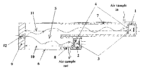
Figure 9 portrays the details of the components layout for an especially
preferred embodiment of a specially designed air sampler 24 encompassing the
10 Calibration Master 20 in the same package. The specially designed air
sampler
24 comprises a small air pump 26 whose inlet 27 is connected to one end 28 of
an
air-tight telescopic sampling tube 29 (see Figures 9 and 10). Outlet 30 of air
pump 26 is connected to inlet 31 of an air-tight confined space 32 wherein an
AB
designed NDIR gas sensor 33 is located. Outlet 34 of confined space 32 leads
to
15 free space 35 outside of specially designed air sampler 24. Air pump 26
is
powered by a battery pack 36 and controlled by an ON/OFF switch 37 all located
inside the air sampler unit 24. Also confined inside air sampler unit 24 is
Calibration Master 20 whose printed circuit board (PCB) (not shown in Figure
9)
interfaces with AB designed NDIR gas sensor 33 on one side and a LCD display
20 38 and a keypad 39 on the other. Whereas LCD display 38 shows operator
21 of
Calibration Master 20 what is going on at any one time, keypad 39 allows
operator
21 to issue functional commands to Calibration Master 20 in order for it to
carry
out the ERC routine.
An air-tight telescopic sampling tube 29 (see Figure 10), when not in use, is
25 lodged by two clamps 40 and 41 located on the right-hand-side of air
sampler unit
24. Unlike an ordinary telescopic tubing where the joints of its sections may
not
normally be designed to be air-tight, the telescopic tubing 29 (see Figure 10)
of air
sampler 24 is, in an especially preferred embodiment, specifically designed to
have substantially air-tight sections so that air does not get into air
sampler unit 24
during sampling except through inlet 42 of telescopic sampling tube 29 (see
Figures 9 and 10). The air-tight telescopic sampling tube 29 might be 6 ft.
long
when fully extended with 9 sections and an outside diameter of 0.5". When all
its
CA 02837588 2013-11-27
WO 2012/166585
PCT/US2012/039539
16
sections are drawn back, its length is around 8". In theory this air-tight
sampling
tube 29 can be of any length and any diameter as long as it is convenient to
use
for air sampling under all circumstances.
So far the ERC procedure has been described in terms of how it can be
accomplished in the field. It should be noted that the ERC procedure can be
accomplished very quickly, without the need for using standard gasses, which
greatly reduces the cost of the procedure In practice, it is important to
realize that
the ERC procedure allows a technician to check calibration of large numbers of
sensors in short periods of time, a limiting factor being the time necessary
to move
between sensors and a short amount of time needed for an ERC procedure.
In an especially preferred embodiment of the ERC procedure, each gas
sensor has a unique identification number. A Calibration Master can address a
particular gas sensor via its unique ID number and can request instantaneous
data from it in order to ascertain whether the gas sensor is accurate.
To increase the efficiency of the ERC procedure, in an especially preferred
embodiment, software is included in Calibration Master 20 (e.g., in processor
memory or other memory media) to facilitate the ERC process and also allow
Calibration Master 20 to interact with a computer (e.g., by use of the
Internet, a
LAN, a WAN or hardware device) where information from Calibration Master 20
can be collected and utilized with one or more computer program modules to
track
compliance with scheduled calibration checks. Thus, for example, each time an
ERC procedure is performed, Calibration Master 20 can create and store a data
file containing desired information such as the unique identifier of the gas
sensor
being checked, the gas concentration detected by the gas sensor, the date and
time of the procedure, whether the gas sensor was recalibrated and any other
desired information. If
desired, automatic reports documenting the ERC
procedure, and its results, can be generated, stored or sent to one or more
additional locations electronically, such as through, for example, an Internet
connection. Because the information used to generate such results is stored
electronically, human error is minimized and, if desired, the system can be
configured with sufficient safeguards so as to prevent doctoring of
calibration
CA 02837588 2013-11-27
WO 2012/166585
PCT/US2012/039539
17
results, thus guaranteeing better information regarding long term stability
results
of gas sensors subjected to the ERC procedure.
It is also worth pointing out that a Calibration Master can be configured so
that it can be used to test multiple gas sensors used to sense different types
of
gasses or a single gas sensor that can detect multiple gasses. For example, a
single gas sensor might be configured so that it can detect both CO2 and water
vapor, and a single Calibration Master can be designed to calibrate the sensor
for
both gasses.
Accordingly, the present invention has now advanced a novel Re-
calibration methodology applicable only to AB designed NDIR gas sensors and
apparatus that can be used to perform such methodology. The final portion of
the
present invention will now address how a specially designed AB NDIR gas sensor
can be made to recalibrate itself without the need for using a Calibration
Master
as described earlier to carry out a re-calibration procedure.
Using the optical component layout for an Absorption Biased ND1R gas
sensor as depicted in Figure 1, the first step is to install a "Standard"
Signal
channel detector 43 and a "Standard" Reference detector 44 both equipped with
the same and identical band-pass filter 45 neutral to the detection of the
target
gas respectively next to the Signal channel detector 5 and the Reference
channel
detector 6 as shown in Figure 11. As disclosed earlier, both Signal channel
detector 5 and Reference channel detector 6 are equipped with the same narrow
band-pass filter 8 which is used to detect the gas of interest in the sample
chamber 9 (see Figures 1 and 11). Detectors 5, 6, 43 and 44 are all of the
same
kind but each has its own spectral filter. Detectors 5 and 6 have the same
spectral filter for the detection of the target gas whereas detectors 43 and
44 have
the same filter that is neutral to the detection of the target gas, i.e.
passing no
radiation that would be absorbed by it. As a matter of fact, detectors 5 and 6
in
the component layout configuration for an AB designed NDIR gas sensor as
shown in Figure 1 are single channel detectors. When detectors 5 and 43 and
also detectors 6 and 44 are installed next to each other together as pairs,
they can
be, respectively, two dual-channel detectors 46 and 47 (see Figure 11). The
values for the CWL and FWHM for filter 8 depend upon which target gas the
CA 02837588 2013-11-27
WO 2012/166585
PCT/US2012/039539
18
sensor is designed to detect. The CWL for neutral band-pass filters 45 (see
Figure
11) can be at 2.20p, 3.91p or 5.00p with a FWHM of ¨0.1p. None of the common
gases encountered by the general public everyday including those in the
atmosphere have absorption bands at these wavelengths within the specified
spectral pass-band of ¨0,1p.
A new sensor parameter called "Standard GAMMA" which is the ratio of the
output of the "Standard" Signal channel detector 43 over the output of the
"Standard" Reference channel detector 44 (see Figure 11) is now defined and
created. First of all, the value of "Standard GAMMA" is independent of the
presence of the target gas in the sample chamber since the spectral filters
that the
"Standard" detectors carry are neutral to the detection of the target gas. In
other
words, the radiation passed by these filters will not be absorbed by the
target gas
in the sample chamber of the sensor. The "Standard GAMMA" is therefore
unrelated to the measurement Physics of the AB designed NDIR gas sensor but
serves to monitor the performance characteristics of all the sensor components
over time. Should there be any change at all in the performance
characteristics of
the sensor components over time, e.g. due to aging, the value of "Standard
GAMMA" will change accordingly. The value of the regular Go of the AB designed
NDIR gas sensor will also change when the performance characteristics of the
sensor components change over time and hence affect the calibration curve of
the
sensor. But the only way to compensate for the change of the Go value in order
to
restore the measurement accuracy of the sensor is to update it from time to
time.
This can be done by flowing 100% dry N2 through the sample chamber of the
sensor and re-determine the correct Go value or to execute the re-calibration
methodology disclosed earlier above. The present invention advances a third
way
to update the value of Go when there are changes in the performance
characteristics of the sensor components over time by taking advantage of the
definition and creation of the concept for "Standard GAMMA".
As it turns out, since both values of the regular Go and "Standard GAMMA"
are affected only by the changes in the performance characteristics of the
sensor
components over time and are both independent of the measurement Physics of
the AB designed NDIR gas sensor, they actually are directly proportional to
each
CA 02837588 2013-11-27
WO 2012/166585
PCT/US2012/039539
19
other. Because of this fact, any change taking place in the regular Go can be
corrected by knowing the change in the value of "Standard GAMMA" over the
same period of time. As a matter of fact, by measuring the value of "Standard
GAMMA" and storing it along with the initial calibration curve, namely (A1,
A2, A3,
A sensor according to the present invention is ideally suited for use with the
15 HVAC&R industry, especially when numerous such sensors are networked
together in a single structure, such as a building. The accuracy gained by
continued self-commissioning allows networked sensors to now fulfill a long-
felt
need for stable sensors. In addition, multiple sensors can be combined within
a
single sensor unit, by adding one or more additional pairs of detectors, one
of
CA 02837588 2013-11-27
WO 2012/166585
PCT/US2012/039539
used to self-commission the multiple gas detectors contained in the same
single
sensor.
In summary, the present invention discloses a powerful new NDIR gas
sensor that is self-commissioning, that can detect one or more target gasses,
5 which can be networked for inclusion in sophisticated networking
applications that
have gone unused to date for want of suitable sensors. The self-commissioning
sensors disclosed herein ensure that such sensors will represent a major
advance
in the field of NDIR gas sensors.
But, as important as self-commissioning is, it is still possible that sensors
10 according to the present invention may ever so slowly drift over time,
albeit in an
amount of time much longer than presently encountered within the industry. The
reason for this is the lack of a perfect source. The present invention ensures
that
changes in the intensity or spectral content of the source will be corrected
by self-
commissioning. Yet, if there is physical change in the source that affects its
15 radiation pattern, which might theoretically occur if, for example,
there is sagging
of a filament in an incandescent light bulb or possible bubbling on a MEMS
source, there is a possibility of a very slight drift over a long period of
time that
cannot be corrected by self-commissioning. Luckily, however, this theoretical
problem can be overcome by also using the re-calibration methodology disclosed
20 earlier in this application.
So, in conclusion, when a sensor according to the present invention is also
equipped to take advantage of re-calibration methodology that uses a
Calibration
Master NDIR gas sensor to calculate a master gas concentration which is used
to
recalibrate the sensor, or multiple master gas concentrations if the sensor is
being
used to detect multiple gas concentrations, a drift-free sensor is truly
obtained
which, if it ever does drift, can easily be recalibrated. And, even if the
sensor
never does drift, its users will know it can quickly be checked and
recalibrated if
need be. This then represents about as perfect an NDIR sensor as there ever
has
been, one that can only be improved with respect to drift by use of a perfect
source.
The invention has been described herein with reference to certain earlier
disclosures by the author presented for illustration and explanation only
should not
CA 02837588 2013-11-27
WO 2012/166585
PCT/US2012/039539
21
limit the scope of the invention. Additional modifications and examples
thereof will
be obvious to those skilled in the art having the benefit of this detailed
description.
Further modifications are also possible in alternative embodiments without
departing from the inventive concept.
Accordingly, it will be apparent to those skilled in the art that still
further
changes and modifications in the actual concepts described herein can readily
be
made without departing from the spirit and scope of the disclosed inventions
as
defined by the following claims.