Note : Les descriptions sont présentées dans la langue officielle dans laquelle elles ont été soumises.
CA 02838443 2014-01-09
CONTINUOUS FUSE STRUCTURE FOR COMBINATION FIREWORKS
FIELD OF THE INVENTION
[0001] This invention relates to combination fireworks, and in particular to a
fuse structure for
combination fireworks and a method of manufacture.
BACKGROUND OF THE INVENTION
[0002] Chinese National Standard GB10631-2004 entitled "Fireworks and
Firecracker - Safety
and Quality", GB19593-2004 entitled "Fireworks and Firecracker - Combination
Fireworks" and
other normative references govern the requirements for combination fireworks,
which are a
combination of a plurality of single tube fireworks devices. Usually, the
structure is formed of a
plurality of rows of paper tubes, such as rectangles, cylinders, diamond
shapes and fan-shaped
bodies. The paper tube chamber is stuffed with propellant powder and effects,
which are ignited
through the fuses. The fuse structure of prior art combination fireworks are
typically made as
follows. Two holes are drilled in each tube wall, one is the fire entry hole
into which fire enters
and the other is the fire hole or fire transmission hole out of which fire
exits. The fuses are
divided into several short parts. The tubes are connected together by
inserting the respective
ends of a fuse part into the fire hole of one tube and the fire entry hole of
an adjacent tube.
[0003] For example, the prior art 25-shot products comprise 5 tube rows X 5
single tubes per
tube row as shown Fig. 1. The transfer order is in accordance with the fire
lines 26 marked with
arrows. The first tube row comprises the head-end of the paper tube series,
starting with tube 11,
followed in sequence by adjacent tubes 12, 13, 14 and 15. The long ignition
fuse 20 is inserted
1
CA 02838443 2014-01-09
into the fire entry hole (not shown) of tube 11. Tube 12 is adjacent to tube
11. The fire hole of
tube 11 and fire entry hole of tube 12 are connected by inserting therein the
two ends of short
fuse 21. Tube 13 is adjacent to tube 12. In a similar manner, the fire hole of
tube 12 and fire
entry hole of tube 13 are connected by inserting therein into the two ends of
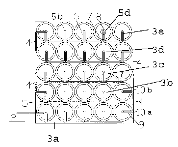
short fuse 22. Tube
14 is adjacent to tube 13. The fire hole of tube 13 and fire entry hole of
tube 14 are connected by
inserting therein into the two ends of short fuse 23. Tube 15 is adjacent to
tube 14. The fire hole
of tube 14 and fire entry hole of tube 15 are connected by inserting therein
into the two ends of
short fuse 24.
[0004] Tube 16, which is located adjacent tube 15 is the first tube of the
next row. To join the
next adjacent row, the fire hole of tube 15 and fire entry hole of tube 16 are
connected by
inserting therein the two ends of short fuse 25, forming an inter-row fire
transmission, and so on.
A second long fuse (not shown) is inserted into the fire hole of tube 30,
which is located at the
end of the last row. The second long fuse is used as a spare ignition fuse.
[0005] In the illustrated prior art fuse structure, the fire-order is as
follows: 1) ignition of fuse
20; 2) the propellant powder in tube 11 ignites short fuse 21 out of fire hole
of tube 11 and into
fire entry hole of tube 12; 3) the propellant powder in tube 12 ignites short
fuse 22 out of fire
hole of tube 12 and into fire entry hole of tube 13, and so on until the
series ends.
[0006] In case there is a fault in firing, the spare ignition fuse can be
ignited for a second ignition
at tube 30, which is in a reverse fire transmission order. In this situation,
the fire holes have the
function of fire entry holes and vice versa.
2
CA 02838443 2014-01-09
[0007] There are several drawbacks to the prior art fuse structure. First,
there is a lack of
reliability in fire transmission and ignition. The potential of eliminating
fire transmission failures
is very low as the plurality of short fuses are connected but not as a
singular fuse, particularly in
each paper tube chamber where failures too frequently occur. Misfiring occurs
once a fault has
taken place at any fire transmission point, which not only leads to a firing
failure affecting the
fireworks display, but also may cause accidents during post-failure
inspection. Second, to form a
prior art fuse structure, it is necessary to cut a long fuse into multiple
small parts. As the long
fuse is covered by a cladding made of gunpowder, the cutting undermines the
fuse's lumen
gunpowder distribution, and impacts the fire transmission performance. In
addition, gunpowder
contact is inevitable during the manual or mechanical cutting process, which
is dangerous.
Third, the procedure for processing traditional fuse structures is complicated
and inefficient.
Besides fuse cutting, punching or drilling (twice) in each tube and insertion
of the short fuses are
also required, and have to be done manually. During the fuse insertion
process, soft and short
fuses are inserted into the small holes of two adjacent tubes which are
difficult to be conducted
reliably and efficiently by mechanical processes.
[0008] To overcome the problems of the prior art, an improved fuse structure
for combination
fireworks is needed.
SUMMARY OF THE INVENTION
[0009] In order to address the above drawbacks, there is provided a continuous
fuse structure for
combination fireworks, which is reliable in fire transmission and ignition,
and simple and
3
CA 02838443 2014-01-09
convenient in production and processing. The continuous fuse structure for
combination
fireworks comprises a plurality of single tubes, each tube comprising one or
more fire units.
Each of the two or more single tubes has at least one fire hole located on the
tube side wall. Fire
passes along a long segment fuse throughout each of the at least one fire hole
of the two of more
single tubes and each of the one or more fire units. The long segment fuse
joins adjacent tubes
together, a portion of the fuse being folded and inserted into each tube in at
least one fire hole.
[0010] Optionally, adjacent tubes in a second and subsequent rows are
connected either with a
separate connecting fuse or a connecting part of the same fuse. According to
the fire sequence,
each folded portion of the fuse is sequentially inserted in the at least one
fire hole of each single
tube. In embodiments of combination fireworks comprising multiple fire units,
the flame spreads
along the fuse or fuses through the separate fire units and tubes.
[0011] In a first embodiment comprising a plurality of tubes in a row, one
fuse joins all the
tubes, each tube comprising one fire hole, with a portion of the fuse being
folded back onto itself
and inserted into each fire hole.
[0012] In a second embodiment, comprising a plurality of rows of tubes, the
end-tube of one row
is connected to the head-tube of an adjacent row with a connecting fuse, the
end-tube and head-
tubes being adjacent each other. Each tube comprises at least one fire hole,
the connecting fuse
joining the end-tube and head-tube.
4
CA 02838443 2014-01-09
[0013] In a third embodiment, the end-tube and head-tube each have two fire
holes, one fire hole
being to connect the tubes in the same row with a fuse and the other fire hole
to connect the end-
tube and head-tube with a connecting fuse.
[0014] In a fourth embodiment, each row has two or more fuses connecting
adjacent tubes. Each
tube in the row can have one or more fire holes.
[0015] In a fifth embodiment, all tubes in all rows are connected with one
continuous fuse, each
tube having one fire hole. The end-tube of one row and head-tube of the next
row are connected.
[0016] A method of constructing a continuous fuse structure for combination
fireworks is further
disclosed, comprising the steps of positioning two or more tubes in a row,
pasting a continuous
bottom paper to the row, the bottom paper covering at least a part of each
tube, punching at least
one hole in each tube through the bottom paper, providing a fuse which is
longer than the width
of the two or more tubes, inserting a folded segment or portion of fuse in
each hole, and pasting a
continuous surface paper on top of the fuse and continuous bottom paper, the
continuous surface
paper covering the exposed portions of the fuse and forming a fire channel.
[0017] The invention has several advantages. The fuse of the entire
combination fireworks can
be comprised of one or more parallel and continuous fuses, which means the
entire combination
fireworks can be joined by one fire transmission unit. There is no need to cut
smaller fuse
segments in the fire transmission unit, resulting in less gun powder waste and
higher safety. In
some embodiments, only one punched or drilled hole per tube is required. The
process of fuse
CA 02838443 2014-01-09
insertion is simplified, which allows for reliable, highly efficient
mechanical production. Fire is
transmitted between adjacent tubes through a continuous fuse as opposed to
prior art point-to-
point fire transmission. In one embodiment, two parallel roundabout fuses are
adopted for in-
tube ignition and fire transmission, and the two fuses are connected at the
corner in the tube and
approach closely in the fire transmission hole. Once the fuse is lit, the fire
sources are ignited
one by another, forming an ignition surface clear of ignition dead spaces,
thereby reducing or
completely eliminating the occurrence of misfires, and resulting in higher or
total ignition rates
for the combination fireworks.
[0018] In addition, the ignition speed of each single tube is controlled at
the outer part of the
successive fuse, which excludes the probability of fire transmission in the
single tube, and also
greatly improves the timing and reliability of the fireworks, which is
particularly important for
products requiring high ignition timing accuracy. Therefore, the beneficial
effects of this
invention include reliable and accurate ignition and fire transmission, and
simplified production
and processing.
[0019] In embodiments where the fire transmission unit comprises a number of
successive
adjacent single tubes, the "number" of tubes refers to the single tube number,
which may be two,
three, four, etc... and the maximum number depends on the number of
combination fireworks.
Preferably, the fire transmission unit comprises at least three consecutive
adjacent single tubes.
[0020] Generally, the combination fireworks are formed by several rows, each
row comprising
several single tubes. In order to maintain the compatibility with the original
process and reduce
6
CA 02838443 2014-01-09
the difficulty of the process, preferably, each tube row of the combination
fireworks forms a fire
transmission unit, and the plurality of fire transmission units are connected
by connector fuses.
Of course, in accordance with the needs of the set off design, each tube row
can be split into a
number of fire transmission units.
[0021] To improve the ignition reliability, preferably, the fire transmission
unit has a row
connecting fuse with two folded portions, each of the two folded portions
being inserted into the
respective fire hole of an end-tube and head-tube at a specific connection
position of the two fire
transmission units. To improve the reliability of fire, as a further
preferable choice, the fire entry
hole and the fire transmission hole is the same hole.
[0022] In order to prevent the occurrence of cross-firing, and improve the
moisture-proof and
anti-damage performance of the combination fireworks, the fuse joining tubes
in each single tube
row of the combination fireworks are disposed between a bottom paper layer and
a surface paper
layer, which are continuous paper layers. Each tube row forms one fire
transmission unit, the
fuse connecting the single tubes in the row. Row connecting fuses join two
adjoining fire
transmission units.
[0023] An exemplary embodiment of the invention provides a combination
fireworks device
including at least one fire transmission unit comprising a plurality of single
tubes placed in
successive arrangement, wherein each of the plurality of single tubes
comprises a fire hole
located on the tube side wall, and a single, continuous fuse connecting the
plurality of single
tubes to each other in series, wherein a portion of the fuse extends into the
fire hole of each of
7
CA 02838443 2014-01-09
the plurality of single tubes and the portion of the fuse is a length of said
fuse folded back onto
itself in each fire hole.
[0024] In a feature of this embodiment, the at least one fire transmission
unit is a plurality of fire
transmission units, each of the plurality of fire transmission units including
a head-unit and an
end-unit, the head-unit and end unit of each fire transmission unit further
including a second fire
hole. The device further includes a second fuse connecting the end-unit and
the head-unit of
adjacent fire transmission units, wherein a portion of the second fuse extends
into the second fire
hole of each end-unit and head unit of adjacent fire transmission units, in
series. The portion of
the second fuse includes a length of the second fuse folded back onto itself
in each second fire
hole.
[0025] In another feature of this embodiment, the at least one fire
transmission unit includes a
plurality of fire transmission units, each of the plurality of fire
transmission units comprising a
head-unit and an end-unit, and the fuse connects each end-unit and head unit
of adjacent fire
transmission units.
[0026] In a further feature of this embodiment, the at least one fire
transmission unit includes a
plurality of fire transmission units, each of the plurality of fire
transmission units including a
head-unit and an end-unit. The device further includes a second fuse
connecting the end-unit and
the head-unit of adjacent fire transmission units, wherein a portion of the
second fuse extends
into the fire hole of each end-unit and head unit of adjacent fire
transmission units in series,
wherein the portion of the second fuse comprises a length of said second fuse
folded back onto
8
CA 02838443 2014-01-09
itself in each fire hole. Preferably, the device further includes at least two
adjacent rows, each of
the rows including at least two of the plurality of fire transmission units,
wherein each of the
rows includes a head-unit and an end-unit, the head-unit and end-unit of each
of the rows further
includes a second fire hole, and a third fuse connecting the end-unit and the
head-unit of adjacent
rows, wherein a portion of the second fuse extends into the second fire hole
of each the end-unit
and head-unit of adjacent rows, and the portion of the third fuse includes a
length of the third
fuse folded back onto itself in each second fire hole.
[0027] In a still further feature of this embodiment, the device also includes
a first continuous
paper layer attached to the fire transmission unit connecting the single
tubes, and a second
continuous paper layer attached to the first continuous paper layer, wherein
the fuse is disposed
between the first paper layer and said second paper layer. Preferably, the
device further includes
a hole punched through the first paper layer and into each of the single tubes
to create the fire
hole.
[0028] In another exemplary embodiment of the invention, there is provided a
combination
fireworks device including a fire transmission unit including a plurality of
single tubes placed in
successive arrangement, wherein each of the plurality of single tubes includes
a fire hole located
on the tube side wall, and a single, continuous fuse connecting the plurality
of single tubes to
each other in series, wherein a portion of the fuse extends into the fire hole
of each of the
plurality of single tubes and the portion of the fuse includes a length of the
fuse folded back onto
itself in each fire hole.
9
CA 02838443 2014-01-09
[0029] In a feature of this embodiment, the device further includes a second
fire transmission
unit adjacent to the first fire transmission unit including a plurality of
single tubes placed in
successive arrangement, wherein the first fire transmission unit and the
second fire transmission
unit each comprise a head-unit and an end-unit, the head-unit and end-unit of
each fire
transmission unit further including a second fire hole, and a second fuse
connecting the end-unit
of the first fire transmission unit and the head-unit of the second fire
transmission unit, wherein a
portion of the second fuse extends into the second fire hole of each end-unit
and head unit of
adjacent fire transmission units, wherein the portion of the second fuse
includes a length of the
second fuse folded back onto itself in each second fire hole.
[0030] In another feature of this embodiment, the device further includes a
second fire
transmission unit adjacent to the first fire transmission unit including a
plurality of single tubes
placed in successive arrangement, wherein the first fire transmission unit and
the second fire
transmission unit each include a head-unit and an end-unit, wherein the fuse
further connects the
end-unit of the first fire transmission unit and the head-unit of the second
fire transmission unit,
wherein a portion of the fuse extends into the fire hole of the end-unit of
the first fire
transmission unit and the head-unit of the second fire transmission unit,
wherein the portion of
the fuse includes a length of the fuse folded back onto itself in each fire
hole.
[0031] In a further feature of this embodiment, the device further includes a
first continuous
paper layer attached to the fire transmission unit connecting the single
tubes, and a second
continuous paper layer attached to the first continuous paper layer, wherein
the fuse is disposed
between the first paper layer and the second paper layer.
CA 02838443 2014-01-09
[0032] In yet another exemplary embodiment of the invention, there is provided
a continuous
fuse structure for combination fireworks including a plurality of single tubes
placed in successive
arrangement so as to form an array, one or more of the plurality of single
tubes comprising a fire
unit, each of the plurality of single tubes comprising at least one fire hole
located on the tube side
wall, one or more fuses for connecting adjacent single tubes to each other, a
first portion of the
one or more fuses extending into the at least one fire hole of a first single
tube and a second
portion of the same one or more fuses extending into the at least one fire
hole of a second single
tube, the first and second single tubes being adjacent each other, so as to
connect in series all the
single tubes of the array, wherein each of the first and second portions of
the one or more fuses is
folded back onto itself in each of the at least one fire hole.
[0033] In a feature of this embodiment, the device further includes one or
more of the plurality of
single tubes including a second fire unit adjacent to the first fire unit,
wherein the first fire unit
and the second fire unit each include a head-unit and an end-unit, the head-
unit and end-unit of
each fire unit further includes a second fire hole, a second fuse connecting
the end-unit of the
first fire unit and the head-unit of the second fire unit, wherein a first
portion of the second fuse
extends into the second fire hole of the end-unit of the first fire unit and a
second portion of the
second fuse extends into the second fire hole of the head-unit of the second
fire unit, wherein
each of the first and second portions of the second fuse is folded back onto
itself in each of the
second fire holes.
11
CA 02838443 2014-01-09
[0034] In another feature of the embodiment, the device further includes one
or more of the
plurality of single tubes making a second fire unit adjacent to the first fire
unit, wherein the first
fire unit and said second fire unit each include a head-unit and an end-unit,
wherein the first
portion of the one or more fuses extending into the at least one fire hole of
the end-unit of the
first fire unit and the second portion of the same one or more fuses extends
into the at least one
fire hole of the head-unit of the second fire unit, wherein each of the first
and second portions of
the one or more fuses is folded back onto itself in each of the at least one
fire hole.
[0035] In a further feature of the embodiment, the device further includes a
first continuous
paper layer attached to the fire unit connecting the single tubes of the fire
unit, and a second
continuous paper layer attached to the first continuous paper layer, wherein
the one or more fuses
are disposed between the first paper layer and the second paper layer.
[0036] These and other exemplary features and advantages of the present
invention will become
clear from the following description with reference to the accompanying
drawings.
BRIEF DESCRIPTION OF THE DRAWINGS
[0037] The foregoing and other exemplary purposes, aspects and advantages will
be better
understood from the following detailed description of exemplary embodiments of
the invention
with reference to the drawings. Embodiments are illustrated by way of example
and not
limitation in the following figures, in which like references indicate similar
elements.
[0038] Fig. 1 is a structure diagram for a typical prior art 25-shot
combination fireworks;
12
CA 02838443 2014-01-09
[0039] Fig. 2 is a structure diagram for a first embodiment of the present
invention;
[0040] Fig. 3 is a longitudinal sectional diagram for the embodiment of Fig. 2
of the present
invention;
[0041] Fig. 4 is a cross-sectional diagram for the embodiment of Fig. 2 of the
present invention;
[0042] Fig. 5 is a cross-sectional diagram for a second embodiment of the
present invention;
[0043] Fig. 6 is a cross-sectional diagram for a third embodiment of the
present invention; and
[0044] Fig. 7 is a front view illustration of a fourth embodiment of the
present invention.
DETAILED DESCRIPTION
[0045] Example embodiments, as described below, may be used to provide a fuse
structure for
combination fireworks and a method of manufacture.
[0046] A first embodiment is illustrated in Figs. 2-4. The specific structure
of this invention,
illustrated as a 25-shot combination fireworks, may equally be applied to
smaller or larger-shot
combination fireworks as described herein. The illustrated embodiment
comprises 5 tube rows X
single tubes per row, ignited by ignition fuse 2. The transfer order is in
accordance with the fire
line 26 marked with arrows in Fig. 2. Other embodiments may include 2 x 2, 3 x
3, 4 x 4, 7 x 7,
13
CA 02838443 2014-01-09
etc. tube arrays and further may include 2 x 3, 3 x 2, 2 x 4, 4 x 2, etc.
combinations, as will be
appreciated.
[0047] As illustrated, the combination fireworks include five fire
transmission units. Five single
tubes la, lb, lc, id, le in each tube row form one fire transmission unit. On
the side walls of
each single tube is a fire transmission hole 5, as shown in Fig. 4. Fire
spreads along a continuous
long fuse 3a which extends between each single tube of the first fire
transmission unit. As
illustrated, further long fuses 3b, 3c, 3d, 3e extend between each single tube
of the other fire
transmission units in a similar manner as long fuse 3a. In embodiments
comprising n fire
transmission units, there are n long fuses joining the single tubes in each of
the n fire
transmission units.
[0048] Each of long fuses 3a, 3b, 3c, 3d, 3e joins the single tubes in a
similar manner. As shown
in the top fire transmission unit of Fig. 4, long fuse 3e is folded and
inserted into each of the five
single tubes' respective fire transmission hole 5 (see position 6). Fig. 3
shows a longitudinal
sectional view with the parallel segments 6 of the folded long fuse for a
given tube 1 in a fire
transmission unit.
[0049] The end-unit of one fire transmission unit or row is coupled to the
head-unit of the next
fire-transmission unit or row. With reference to the fuse connection between
the first and second
fire transmission units of Fig. 4, row connecting fuse 4 comprises two folded
portions 9 the first
folded portion 9 is inserted in the end-unit at fire transmission hole 10a,
and the second folded
portion 9 is inserted in the adjacent head-unit at fire transmission hole 10b.
Similar connecting
14
CA 02838443 2014-01-09
fuses 4 join the other end-unit tubes to adjacent head-unit tubes. As can be
seen from Fig. 4,
there is no need to cut small fuses in the fire units, and only one punched or
drilled hole is
required in most of the tubes. In comparison with prior art point-to-point
fire transmission, Fig.
4 shows how fire is transmitted through the continuous fuses.
[0050] For ease of understanding, the tubes in the first row are referred to
as la, lb, lc, etc. The
tubes in the second row (not numbered in Fig. 5) would be referred to 2a, 2b,
2c, etc. As such,
the second tube in the fifth row is identified as 5b. As shown in tube 5d, two
parallel portions of
long fuse 3e are folded and formed for insertion in fire transmission hole 7
(circled inner
portion), the bend shown within tube 5d at bend location 8 (circled inner
portion). Once the fuse
is lit, the fire sources are ignited one after another, forming an ignition
surface free of ignition
dead spots.
[0051] A second embodiment is illustrated in Fig. 5. Compared to the first
embodiment where
each of the five tubes in a fire transmission unit is coupled by one long
fuse, Fig. 5 illustrates two
or more tubes within a given fire transmission unit coupled together by fuses
that are shorter in
length than a long fuse. In the first row, there are two fire transmission
units, namely a first fire
transmission unit comprising tubes lf, lg, and lh and a second fire
transmission unit comprising
tubes ii and 1j. A first fuse 100 joins tubes 1 f to 1 g and tubes 1 g to lh.
A second fuse 102
connects tube ii to tube lj only. A unit connecting fuse 101 joins the two
fire transmission units
as it is inserted in tube lh of the first fire transmission unit and tube 1 i
of the second fire
transmission unit. Fire spreads between fire transmission units since unit
connecting fuse 101
shares fire holes with tubes of each adjacent fire transmission unit. In
another embodiment,
CA 02838443 2014-01-09
tubes on the end of adjoining fire transmission units may be designed with
separate fire
transmission holes for the connector fuses. As illustrated in this embodiment,
not all the rows
require the same number of fire transmission units. The rows that have two
fire transmission
units must have unit connecting fuses joining adjoining fire transmission
units.
[0052] A third embodiment is illustrated in Fig. 6. Compared to the first
embodiment where
each of the five tubes in a fire transmission unit is coupled by one long fuse
and the resulting
array has five long fuses, Fig. 6 illustrates a combination fireworks
comprising only one fire
transmission unit, and only one continuous fuse 201 is used for fire
transmission through single
tubes and the five tube rows. An end-unit tube is connected to an adjacent
head-unit tube with a
segment of continuous fuse 201 which wraps around end-unit tube, in the
illustrated
embodiment. Depending on the number of tubes and placements, it is
contemplated for the
joining segment to be of different lengths and orientations. In this
embodiment, the terms "end-
unit" and "head-unit" are in relation to the configuration (eg: the 5 x 5
array) since there is only
one fire transmission unit.
[0053] In the first three embodiments, the single tubes are connected in
series, such that when
the long fuse 2 in Figs. 2 and 4 is ignited, the fire unit in the first tube
is ignited, fuse 3a is
ignited, the fire unite in the second tube is ignited, fuse 3b is ignited and
so on. After the last tube
in the first row, namely the fifth tube 1 e in the illustrated embodiment, is
ignited, connecting fuse
4 is ignited, which ignites the first tube in the second row. Each adjacent
tube ignites in series.
16
CA 02838443 2014-01-09
[0054] A fourth embodiment is illustrated in Fig. 7 which shows a front view
of the fire
transmission unit's five tubes. Fuse 301, shown in broken lines, is disposed
between bottom
paper layer 302 and surface paper layer 303, and is therefore hidden from
view. Bottom paper
layer 302 and surface paper layer 303, which are continuous paper layers,
cover at least a part of
each single tube of the fire transmission unit. During manufacture, continuous
bottom paper
layer 302 is pasted at the specified fuse inserting position on the surface of
the tube rows. In the
illustrated example, the position is the lower part of the tubes. A hole is
punched into each tube
through continuous bottom paper layer 302. Segments of fuse 301 are then
inserted into each
hole with folded portions as described above. Then the continuous surface
paper layer 303 is
pasted on top of fuse 301.
[0055] The two joined continuous paper layers form a closed space for fuse 301
which becomes
a fire channel. In this embodiment, the occurrence of cross-firing is
prevented. Furthermore,
moisture exposure is reduced and performance of fuse 301 is increased.
[0056] The described embodiments for the invention are provided to clearly
illustrate the
invention of new technical solutions, and thus are not be understood as
restrictions to the
invention, which are limited by the following claims.
[0057] While the invention has been described in terms of several exemplary
embodiments,
those skilled in the art will recognize that the invention can be practiced
with modification within
the scope of the appended claims.
17
CA 02838443 2014-01-09
[0058] Further, it is noted that, Applicant's intent is to encompass
equivalents of all claim
elements, even if amended later during prosecution.
18