Note : Les descriptions sont présentées dans la langue officielle dans laquelle elles ont été soumises.
CA 02838840 2013-12-09
WO 2012/173924
PCT/US2012/041880
HYDRAULIC FRACTURE MONITORING USING
ACTIVE SEISMIC SOURCES WITH RECEIVERS IN THE TREATMENT WELL
RELATED CASES
Not applicable.
FIELD OF THE INVENTION
[0001] The invention relates to a system and method for monitoring hydraulic
fracturing
using vertical seismic profiling techniques.
BACKGROUND OF THE INVENTION
[0002] In the production of hydrocarbons from subsurface formations, it is
common to
"hydraulically fracture" a formation in order to increase its permeability,
which in turn
enhances its productivity. Typically, a fracturing fluid is injected under
pressure into the
formation through an injection well. In order to determine the effectiveness
of a fracturing
operation, it is desirable to gain information about the rate and extent of
fracturing that
occurs during the injection.
[0003] In water flooding operations, fluids are injected into the subsurface
formation to
mobilize the hydrocarbons towards producer wells. Such injection often needs
to occur at
high pressures, occasionally exceeding the fracture pressure and leading to
unintended
fracturing of the formation and fluids being injected "out of zone." This is
an undesirable
outcome that decreases the effectiveness of the water flood and may result in
early water
breakthrough at the producers or water entering other producing intervals or
overlying
formations. Thus, it is desirable to gain information about the rate and
extent of fracturing
that occurs during the water flooding.
[0004] Various techniques have been proposed for monitoring fracturing. One
such
technique uses passive seismic monitoring that depends on detection of the
microseismic
signals that result from hydraulic fracturing, as recorded in nearby
observation wells or in the
treatment well itself. This process provides information in real-time and
depends on the
existence, strength, and detectability of the microseismic signals. Thus, it
remains desirable
to provide a robust and inexpensive technique that gives accurate and
meaningful
information about fracture growth without these limitations.
SUMMARY OF THE INVENTION
[0005] In accordance with preferred embodiments of the invention there is
provided a
system and method for actively monitoring fracture growth that is not
dependent on
1
detection of microseismic signals. The invention includes the use of active-
source, time- lapse
seismic profiles to collect information about the extent and degree of
fracturing in the subsurface
and can be carried out using sensors in the treatment well, thus eliminating
the need for a second
well.
[0005a] According to one aspect of the invention there is provided a method
for obtaining
information about a hydraulic fracturing operation in a fracture zone in a
well, comprising
the steps of: a) providing at least one acoustic sensor in the well and at
least one acoustic
source; b) injecting fracturing fluid into the well so as to cause fractures
in a fracture zone
in the surrounding formation; c) using the acoustic source to send an acoustic
signal and
using an acoustic receiver to receive the signal; d) repeating step c) at
least once; e)
processing received signals using a microprocessor so as to obtain information
about the
fractures; and f) outputting the obtained information; wherein at least one
acoustic sensor
is in or below the fracture zone and the received signal is a first arrival
and wherein at least
one additional sensor is above the fracture zone, and further including the
step of using
deconvolution or virtual source processing on the signals received at the at
least one
acoustic sensor and the at least one additional sensor to isolate changes in
the formation
from changes in the overburden.
[0006] Vertical seismic profiling is a known technique for making seismic
measurements using
down-hole receivers. Vertical Seismic Profile (VSP) data are typically
obtained by generating one
or more shots from a seismic source located at one or more selected positions
on the surface. The
signal produced by each shot is detected at multiple locations along a
borehole extending into the
formation. The signals can be detected by multiple receivers in the borehole,
or by a group of
receivers that is moved along the borehole. The primary goal of a VSP is
obtaining the subsurface
reflectivity with high vertical resolution.
[0007] Cross-well seismic measurements are similar to VSP measurements, but
are typically
made using a seismic source that is moved along the length of a second well.
The second well only
needs to be close enough to the treatment well to allow seismic signals to
travel from the source to
the receivers in the treatment well.
100081 In some embodiments, the invention provides a method for obtaining
information about a
hydraulic fracturing operation in a well, comprising the steps of a) providing
at least one acoustic
source and at least one acoustic sensor in the well; b) injecting fracturing
fluid into the well so as to
cause fractures in the surrounding formation; c) using the acoustic source to
send an acoustic signal
2
CA 2838840 2018-09-18
and using the acoustic receiver to receive the signal; d) repeating step c);
and e) processing the
received signal using a microprocessor so as to obtain information about the
fractures. The acoustic
source may be at the surface or in a second well. In preferred embodiments, at
least one acoustic
4 sensor is positioned in or below the fractured formation.
100091 The information gained in step d) can be used for controlling the
injection of fracturing
fluid, for monitoring fracture growth, or for characterizing fractures. By way
of example, the
information so gained can be used to build or calibrate subsurface models.
[0010] The method may be carried out using a plurality of acoustic sensors and
the sensors may
comprise distributed acoustic sensors. At least some of the sensors may be
cemented in an annulus
in the well. Preferably, at least 100 sensors are provided and step c) is
repeated after a time period
greater than 1 minute and less than 10 minutes. Step c) is preferably repeated
for at least 1 hour.
2a
CA 2838840 2018-09-18
CA 02838840 2013-12-09
WO 2012/173924 PCMJS2012/041880
[0011] The method can be used to measure first-arriving acoustic waves and the
information gained from the acoustic measurements can be used to detect out-of-
zone
injection. The acoustic data can also be used in a vertical seismic profile
technique.
[0012] As used herein, the terms "above" and "below" shall be understood to
refer to
positions that are relatively nearer to or farther from, respectively, the
earth's surface.
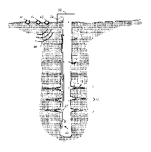
BRIEF DESCRIPTION OF THE DRAWINGS
[0013] For a more detailed understanding of the invention, reference is made
to the
accompanying Drawing, which is a schematic illustration of a seismic operation
in
accordance with one embodiment of the invention.
DETAILED DESCRIPTION OF A PREFERRED EMBODIMENT
[0014] Referring to the Figure, a wellbore 10 contains a length of tubing 12
and a sensor
array 20. Wellbore 10 may be cased or un-cased and there may or may not be
cement in
the annulus adjacent to the borehole wall. Without affecting the concepts
disclosed herein,
well 10 may contain one or more components such as are known in the art,
including but
not limited to packers, guide shoes, float shoes, float collars, stage
collars, multiple tubing
strings, sandscreens, perforating guns, etc (all not shown), and one or more
zones in the
well may be cemented or otherwise sealed or isolated. As discussed below, the
well is
subjected to a hydraulic fracturing force that causes fractures 14 in the
formation
surrounding the borehole. During fracturing, fractures 14 grow outwardly from
the well,
as shown in phantom by reference numeral 15. The portion of the formation in
which
fractures 14 are formed will be referred to as the fracture zone 17.
[0015] Sensor array 20 preferably includes a plurality of acoustic sensors 22
that are
spaced-apart in the borehole and connected by a communication line 24. Sensors
22 can
be geophones, including 3C geophones, hydrophones, or distributed acoustic
sensors, all of
which are known in the art. If sensors 22 are distributed acoustic sensors,
communication
line 24 may comprise an optical fiber with or without Bragg gratings and may
serve as the
sensing array, with or without additional discrete sensors. Sensors 22 can be
positioned
above, throughout, and/or below fracture zone 17.
[0016] Sensors that are above the fracture zone can only give information
about fracturing
using reflected or diffracted waves, not first arrivals, whereas, sensors that
are in or below
the fracture zone can give information about the extent of fracturing using
first arrivals.
3
CA 02838840 2013-12-09
WO 2012/173924 PCMJS2012/041880
[0017] At the surface, various equipment and controls such as are known in the
art are
shown schematically at 30. Surface equipment 30 preferably includes signal-
receiving
means 32 for sensors 22. If sensors 22 are distributed acoustic sensors,
signal-receiving
means 32 may include a lightbox with a computer-controlled laser light source
that is
optically coupled to an optical fiber and an optical receiver for detecting
light that has been
backscattered from points within the fiber. Acoustic waves that are incident
on the optical
fiber cause perturbations in the fiber that can be detected optically using
optical time
domain reflectometry (OTDR), interferometry, or combinations thereof.
[0018] Still referring to the Figure, at least one source 40 may be positioned
on the surface
.. of the earth, near enough to wellbore 10 to allow seismic signals from
source 40 to be
received at sensors 22. If desired, several seismic sources 41, 42 may be
provided at
different positions relative to the wellbore in order to provide more complete
coverage.
[0019] In operation, seismic (acoustic) signals 44 are generated from at least
one source 40
on the earth's surface and are received at down-hole receivers 22. According
to preferred
embodiments receivers 22 are and preferably deployed along a significant
portion of the
length of wellbore 10. This type of seismic measurement is known as VSP. In
preferred
embodiments, receivers are located above, through, and below the fracture
zone, as this
configuration typically gives better results. In particular, seismic signals
travelling from the
surface sources to the sensors in the well can be detected as first arrivals.
[0020] The seismic signals are preferably generated frequently, e.g. every few
minutes, while
the hydraulic fracturing is taking place. The seismic signals may begin before
the fracturing
operation commences and may continue after it ends (e.g., to record the
effects of pressure
dissipation or leak-off). It is preferred to acquire a baseline survey prior
to beginning the
injection of hydraulic fracturing fluid. By way of example only, it may be
desirable to send
an acoustic signal once per minute and to record acoustic data for at least an
hour. In
preferred embodiments, acoustic data may be recorded less frequently, e.g.
with a frequency
less than 1 per minute and greater than 1 per 10 minutes, and is recorded
throughout the
fracturing operation.
[0021] As the injection proceeds and seismic surveys are acquired every few
minutes,
receivers above the fracture zone will not record any changes in times and
amplitudes of first
arrivals. In contrast, receivers in and below the fracture zone will record
changes in first
arrivals over time, depending on the extent of fracturing occurring in the
rocks adjacent to the
well.
4
CA 02838840 2013-12-09
WO 2012/173924 PCMJS2012/041880
[0022] Using the data from receivers above the area of interest as reference,
for instance via
deconvolution, it is possible to isolate changes in arrival times and
amplitudes that are
attributable solely to the fracture zone and not the overburden. By way of
example only, this
can be accomplished using VSP first-arrival tomography or simpler methods.
Reflected and
diffracted waves may also be used, including those arriving at sensors above
the fracture zone.
It will be understood that the data-processing techniques described herein are
performed on a
microprocessor and are known in the art. In instances where there are no
sensors above the
fracture zone, first arrival data may not be available for the overburden,
with the result that
overburden calculations may have to be made using techniques that are known in
the art.
[0023] The resulting seismic data provide information about the rate and
extent of subsurface
fracturing. This information, in turn, can be used as an input in controlling
the rate of
injection of fracturing fluid, in monitoring fracture growth, or for
characterizing fractures, as
well as ensuring that fractures do not extend beyond the intended fracture
zone. Likewise,
the information about fracture growth can be used to build or calibrate
subsurface models.
[0024] While VSP techniques can be implemented with any type of sensor array,
in some
instances it may be preferred to use a distributed acoustic sensing (DAS)
system. DAS is
particularly suitable for VSP because it readily provides a large sensor array
with minimal or
no well intervention and because the nearly vertically incident P and nearly-
horizontally
incident Sv waves are readily detectable using DAS fiber.
[0025] For energy arriving along the wellbore, the known technique of virtual
source imaging
may be used to remove the effects of the overburden. The effect of fracturing
on first-arriving
waves will be seen on time delays (time shifts) and amplitude changes,
presumably on both P
and S waves.
[0026] While DAS favors along-well wave propagation for P waves, if signal and
sensitivity are great enough, P waves approaching broadside can be used. Such
waves
could be generated, for example, by sources arranged in a circle around the
fracturing
operation, far enough distant to favor horizontal propagation by turning, so
as to give a
measure of fracture azimuth and height. By way of example only, this may
entail
positioning the sources such that a direct path between a source and a
receiver in the well
defines an angle of at least 60 from vertical. In addition, Sv waves,
polarized vertically,
could also be arranged to propagate horizontally in a similar way, and these
waves could
provide fracture height and azimuth without requirement of abnormally strong
signal or
sensitivity.
5
CA 02838840 2013-12-09
WO 2012/173924 PCMJS2012/041880
[0027] In alternative embodiments, a fracturing operation may be monitored
using both
active and passive seismic systems simultaneously. Thus for example, with
receivers in
the same well, the signals from active and passive seismic would provide
complementary
information: passive seismic signals are indicative of fracturing of the rock,
while active
.. seismic signals respond to the presence of injection fluids and general
weakening of the
surrounding rock.
[0028] In still other embodiments, one or more seismic sources could
alternatively or
additionally be positioned in a nearby observation well, resulting in a cross-
well geometry.
This configuration is a more intrusive and more complex application, and
results in broadside
arriving waves, disfavoring use of DAS for P waves, which are more effectively
measured
using transversely-oriented or 3C geophones. Nonetheless, DAS will be
effective for
recording Sv waves in this geometry. Cross-well tomography techniques are
known in the
art.
[0029] In instances where there are no sensors in or below the fracture zone,
first arrival data
.. may not be available for the fracture zone, with the result that data
analysis for the fracture
zone may have to be made using reflections or diffraction.
[0030] In any of the embodiments, the concepts disclosed herein can be used to
monitor
water flooding operations and to detect out-of-zone water injection.
[0031] Laboratory experiments and field data suggest that time-lapse effects
may be more
apparent for shear waves than for compression waves, but both wave types are
of interest in
hydraulic fracture characterization. In addition, with sources at the surface,
well separated
from the fracture, diffraction phenomena also become important in the
interpretation. If it is
desirable to measure shear waves, then a seismic source that emits such waves
is important.
For surface sources, both dynamite and vibrating sources (vibroseis) can
provide shear
energy, but not necessarily in a coherent manner or with sufficient strength
at the depths of
interest. Virtual source processing may be used to synthesize shear sources
distributed along
the well from the wavefield produced by strong surface sources. A strong
SeismovieTm
source might give good shear energy and avoid the near-surface attenuation
difficulties. PS
conversions can also produce deep shear energy.
[0032] While the invention has been described in terms of preferred
embodiments, it will
be understood that variations and modifications can be made without departing
from the
scope of the invention which is set out in the claims that follow. In the
claims, unless
explicitly so stated, the sequential recitation of steps is not intended to
require that the steps
6
CA 02838840 2013-12-09
WO 2012/173924 PCT/US2012/041880
be performed in the recited order. In particular, except as stated, the timing
of the
beginning, end, and duration of the injection of fracturing fluid has no
bearing on the scope
of the claims, which relate to the collection of seismic data. Likewise, the
processing of
data may be concurrent with the collection of additional data, data collected
at various
times may be processed separately or together, data may be processed more than
once
and/or in more than one way, and/or data processing can be performed after the
collection
of all data.
7