Note : Les descriptions sont présentées dans la langue officielle dans laquelle elles ont été soumises.
SYSTEM OF TYING, CLEANING AND RE-CEMENTING MASONRY USING PORT
ANCHORS
BACKGROUND OF THE INVENTION
Presently the market has a limited number of marginally
effective or economical ways to address the problem of
delaminating unintentionally voided masonry piers and/or walls
usually associated with separation between leaves (leafs or
layers) of masonry. A restorer has the choice of dismantling and
reconstructing the affected masonry at great expense and
occasional danger, or using an array of existing, externally
applied products and systems to try to knit the masonry back
together but never fully restoring its structural integrity.
Some of the prior options which attempt to but do not meet
current needs or accomplish all of the functions of tying and
cementing voided masonry back together are as follow:
a) Injection Grouting Systems into Voids: These systems
require numerous drill holes to inject grout (to attempt to
"glue" the masonry together) and sometimes separate drill holes
to install anchors, if needed for additional tying of the
masonry. Such systems can only partially rely on the
adhesiveness of the grout to hold the masonry together, and must
therefore rely on the presence of ties, and have little or no
mechanism for scoping and cleaning the voids that must be filled,
thereby establishing a proper, cementing bond. Thus, these
systems can lead to major problems in the stabilization of
masonry and require numerous drill holes which can increase the
potential danger of the repair operation. Some grout injection
systems do not rely on ties, however, these employ high strength
resin or cement based grout formulations that are not physically
compatible with the parent masonry. Also, these systems cannot
1
CA 2838882 2018-10-12
CA 02838882 2013-12-09
WO 2012/174257 PCT/US2012/042484
be used at below 32 degrees F temperature as the grout will not
cure properly and could freeze.
b) Epoxy-Based (Adhesive) Anchor Systems: These systems
involve the insertion of tubular screens into holes that are
drilled through the voided masonry, partial filling of the
screens with epoxy, and then insertion of metal rods. These
provide limited reliability and are not effective in spanning
over large voids as not enough containment pressure is developed
within the screen to uniformly cover all contact surfaces before
the adhesive oozes out of the screen. Also, these systems do not
attempt to actually fill the voids (in order to cement the leaves
back together), and therefore have very limited shear capacity
across wider voids. These systems are not generally suitable for
cold temperature installations where the curing of the adhesive
is slowed or halted.
c) Mechanical Wedge (Mechanical) Anchor Based Systems:
These systems transfer no shear loads and make not attempt to
fill the voids between leaves of masonry, rather, they simply
keep the voids from widening or narrowing.
d) Dry-Set Helical (Mechanical) Anchor Systems: These
systems make no attempt to fill the voids and must be vibrated
and driven into place, potentially damaging and loosening
delicate masonry wall systems during use.
e) Grouted Sock (Adhesion)Anchor Systems: These systems
have only a moderate amount of shear capacity and contain the
grout so that it does not flow into the voids. These systems
will also not work in temperatures of below 32 degrees F as the
grout will not cure.
BRIEF SUMMARY OF THE INVENTION
The present system and method of anchoring and cementing
adjacent and often separated leaves (layered structures) of
2
'
masonry and has the capability of being used for anchoring,
cleaning and flushing of old mortar, and injecting grout into
internal masonry voids, thereby tying and re-cementing or cementing
the masonry mass back together. Various embodiments of anchor
systems are provided for perfoLming the various methods, more
particularly, some of the embodiments describe port anchors which
are used to clean and flush the old mortar and then grout fill the
void between adjacent masonry leaves while other embodiments are
used to grout fill the void. The disclosed methods apply these
various anchor systems to tie adjacent masonry leaves together as
well as clean, flush and fill the void between the leaves. These
embodiments negate the need for expensive and sometimes dangerous
reconstruction of the masonry while providing a much better and
safer result than the other old building masonry restoration
systems that are currently used. Other advantages of the
embodiments are that supplemental, temporary bracing can be
directly attached to the outer ends of the anchors to resist
grouting pressures that would tend to separate the leaves, and
heating wands can be temporarily inserted into the open shanks of
the anchors so that they can be installed under temperatures that
are lower than 40 degrees.
In an aspect, there is provided an anchor system for use with
leaves, layers or other elements of a masonry structure having a
void between the leaves, layers or other elements, comprising: a
hollow tube extending in a longitudinal direction of the anchor
system, the hollow tube having at least one opening therein
extending from an interior of the hollow tube into the void; a hole
located adjacent an end of the hollow tube, the hole permitting a
flowable substance to flow into the hollow tube and out of the at
least one opening in the hollow tube into the void between adjacent
leaves, layers or other elements of the structure;
3
CA 2838882 2019-07-22
a hollow adhesion anchor adjacent an end of the hollow tube, the
hollow adhesion anchor being made of a flexible material having a
hollow interior for receiving the flowable substance therein; and
an anchor adjacent another end of the hollow tube; and a feeder
tube, being separate and distinct from the hole at the end of the
hollow tube, associated with the hollow adhesion anchor for feeding
the flowable substance into the hollow interior of the adhesion
anchor in order to expand the adhesion anchor.
In another aspect, there is provided a anchor system for use
with leaves, layers or other elements of a masonry structure having
a void between leaves, layers or other elements, comprising: at
least one rod extending in a longitudinal direction; a hole located
adjacent one end of the at least one rod, the hole permitting a
flowable substance to flow adjacent the at least one rod into the
void; a hollow adhesion anchor adjacent one end of the at least one
rod, the hollow adhesion anchor being made of a flexible material
having a hollow interior for receiving the flowable substance
therein; an anchor adjacent another end of the at least one rod; a
feeder tube, being separate and distinct from the hole adjacent the
one end of the at least one rod, associated with the hollow adhesion
anchor for feeding the flowable substance into the hollow interior
of the adhesion anchor in order to expand the hollow adhesion
anchor; and an opening adjacent the at least one rod and between the
hollow adhesion anchor and the another anchor, the opening
permitting the flowable substance to flow adjacent the at least one
rod into the void between adjacent leaves, layers or other elements
of the structure.
In another aspect, there is provided a method of repairing
masonry including a masonry structure with first and second leaves
or layers and having a void therebetween, comprising the steps of:
a) providing at least one hole through the first leaf and continuing
through at least a portion of the second leaf; b) inserting an
3a
CA 2838882 2019-07-19
anchor system into the at least one hole through the first leaf and
continuing through the at least a portion of the second leaf such
that a portion of the anchoring system is located within the void
between leaves, the anchoring system comprising: a hollow tube
extending in a longitudinal direction of the anchor system, the
hollow tube having at least one opening therein extending from an
interior of the hollow tube into the void; a hole located adjacent
an end of the hollow tube, the hole permitting a flowable substance
to flow into the hollow tube and out of the at least one opening in
the hollow tube into the void; a hollow adhesion anchor adjacent an
end of the hollow tube, the hollow adhesion anchor being made of a
flexible material having a hollow interior for receiving the
flowable substance therein; an anchor adjacent another end of the
hollow tube; and a feeder tube, being separate and distinct from the
hole at the end of the hollow tube, associated with the hollow
adhesion anchor for feeding the flowable substance into the hollow
interior of the adhesion anchor in order to expand the adhesion
anchor; c) securing a portion of the anchor system within the hole
in the second leaf to secure the anchor system in place; d) securing
another portion of the anchor system within the hole in the first
leaf; e) providing pressurized water or air through an opening
within the anchor system located in the portion thereof within the
void between the first leaf and the second leaf in order to clean
out old grout or cement located within the void; and f) providing
the flowable substance through an opening within the anchor system
located in the portion thereof within the void between the first
leaf and the second leaf permitting the flowable substance to flow
into the void between leaves to secure the leaves of the masonry
structure together.
In another aspect, there is provided a method of repairing
masonry including a masonry structure with first and second leaves
or layers and having a void therebetween, comprising the steps of:
3b
CA 2838882 2019-07-19
a) providing at least one hole through the first leaf and continuing
through at least a portion of the second leaf; b) inserting an
anchor system into the at least one hole in the first leaf and into
the hole in the at least a portion of the second leaf such that a
portion of the anchoring system is located within the void between
leaves, the anchoring system comprising: a hollow tube extending in
a longitudinal direction of the anchor system, the hollow tube
having at least one opening therein extending from an interior of
the hollow tube into the void; a hole located adjacent an end of the
hollow tube, the hole permitting a flowable substance to flow into
the hollow tube and out of the at least one opening in the hollow
tube into the void; a hollow adhesion anchor adjacent an end of the
hollow tube, the hollow adhesion anchor being made of a flexible
material having a hollow interior for receiving the flowable
substance therein; an anchor adjacent another end of the hollow
tube; and a feeder tube, being separate and distinct from the hole
at the end of the hollow tube, associated with the hollow adhesion
anchor for feeding the flowable substance into the hollow interior
of the adhesion anchor in order to expand the adhesion anchor; c)
securing a portion of the anchor system within the hole in the
second leaf to secure the anchor system in place; d) securing
another portion of the anchor system within the hole in the first
leaf; and e) providing pressurized water or air through an opening
within the anchor system located in the portion thereof within the
void between the first leaf and the second leaf in order to clean
out old grout or cement located within the void.
In another aspect, there is provided a method of repairing
masonry including a masonry structure with first and second leaves
or layers and having a void therebetween, comprising the steps of:
a) providing at least one hole through the first leaf and continuing
through at least a portion of the second leaf; b) inserting an
anchor system into the at least one hole in the first leaf and into
3c
CA 2838882 2019-07-19
the hole in the at least a portion of the second leaf such that a
portion of the anchoring system is located within the void between
leaves, the anchoring system comprising: a hollow tube extending in
a longitudinal direction of the anchor system, the hollow tube
having at least one opening therein extending from an interior of
the hollow tube into the void; a hole located adjacent an end of the
hollow tube, the hole permitting a flowable substance to flow into
the hollow tube and out of the at least one opening in the hollow
tube into the void; a hollow adhesion anchor adjacent an end of the
hollow tube, the hollow adhesion anchor being made of a flexible
material having a hollow interior for receiving the flowable
substance therein; an anchor adjacent another end of the hollow
tube; and a feeder tube, being separate and distinct from the hole
at the end of the hollow tube, associated with the hollow adhesion
anchor for feeding the flowable substance into the hollow interior
of the adhesion anchor in order to expand the adhesion anchor; c)
securing a portion of the anchor system within the hole in the
second leaf to secure the anchor system in place; d) securing
another portion of the anchor system within the hole in the first
leaf; and e) providing the flowable substance through an opening
within the anchor system located in the portion thereof within the
void between the first leaf and the second leaf permitting the
flowable substance to flow into the void between leaves to secure
the leaves of the masonry structure together.
More specifically, the anchor system is used to repair a
masonry structure with a pair of leaves having a void between the
leaves. The anchor system is made up of a hollow tube extending in
the longitudinal direction, the hollow tube having at least one
opening therein between the interior of the hollow tube and the
void, an adhesion anchor adjacent one end of the hollow tube, the
adhesion anchor being made of a flexible material configured to have
a hollow interior for receiving a flowable substance therein, an
3d
CA 2838882 2019-07-19
anchor adjacent another end of the hollow tube, a feeder tube
associated with the adhesion anchor for feeding the flowable
substance into the hollow interior of the adhesion
3e
CA 2838882 2019-07-19
CA 02838882 2013-12-09
WO 2012/174257 PCT/US2012/042484
anchor in order to expand said adhesion anchor; and an opening
associated with an end of the hollow tube for permitting a
flowable substance to flow into the hollow tube and out of the at
least one opening in the hollow tube into the void between
adjacent leaves of the structure. Wherein the flowable substance
for the interior of the adhesion anchor may be a hardening
adhesive substance.
In a further embodiment, the hollow tube is replaced with at
least one rod which extends in the longitudinal direction, an
adhesion anchor adjacent one end of the at least one rod, the
adhesion anchor being made of a flexible material configured to
have a hollow interior for receiving a flowable substance
therein, an anchor adjacent another end of the at least one rod,
a feeder tube associated with the adhesion anchor for feeding a
flowable substance into the hollow interior of the adhesion
anchor in order to expand the adhesion anchor, and an open space
adjacent the at least one rod and within the void for permitting
a flowable substance to flow adjacent the at least one rod into
the void between adjacent leaves of the masonry structure.
Further, the method of repairing a masonry structure having
first and second leaves having a void therebetween includes the
steps of: providing at least one hole through the first leaf and
continuing through at least a portion of the second leaf;
inserting an anchor system into the at least one hole in the
first leaf and into the hole in the second leaf such that a
portion of the anchoring system is located within the void
between leaves; expanding a portion of the anchor system within
the opening in the second leaf to secure the anchor system in
place; securing another portion of the anchor system within the
opening in the first leaf; providing pressurized water or air
through an opening within the anchor system located within the
void of the masonry structure in order to clean out old grout or
4
CA 02838882 2013-12-09
WO 2012/174257 PCT/US2012/042484
cement located within the void between leaves; and providing a
flowable substance through the opening within the anchor system
located in the void between the first and second leaf in order to
permit the flowable substance to flow into the void between
leaves to secure the leaves of the masonry structure together and
wherein the flowable substance may be a non-shrinkable hardening
substance.
For a better understanding of the present invention,
together with other and further objects thereof, reference is
made to the accompanying drawings and detailed description, and
the scope of the invention will be set forth in the appended
claims.
BRIEF DESCRIPTION OF THE SEVERAL VIEWS OF THE DRAWING
Figure 1 is a schematic side view of one embodiment of a
port anchor system with one adhesion-based anchor end and one
mechanical or threaded connection end which can be used for
attachment of external bearing plates and bracing, used for
grouting voids and not necessarily cleaning them;
Figure 2 is a schematic side view of another embodiment of a
port anchor system with a pair of adhesion anchors, each at
opposite ends of the anchor system, used for grouting voids and
not necessarily cleaning them;
Figure 3 is a schematic side view of still another
embodiment of a port anchor system with an open shank and one
adhesion anchor end and one mechanical or threaded connection
end, used for cleaning voids and grouting them and attachment of
external bearing plates and bracing;
Figure 4 is a schematic side view of a further embodiment of
a port anchor system with an open shank and a pair of adhesion
anchors, each at opposite ends, used for connection of masonry
leaves and used for cleaning voids and grouting them;
5
CA 02838882 2013-12-09
WO 2012/174257 PCT/US2012/042484
Figure 5 is a schematic side view of still a further
embodiment of a port anchor system with a pair of adhesion
anchors, each at opposite ends as well as a mechanical or
threaded connection at one end, used for grouting voids and not
necessarily cleaning them and attachment of external bearing
plates and bracing;
Figure 6 is a schematic side view of another embodiment of a
port anchor system with an open shank and a pair of adhesion
anchors, each at opposite ends and one mechanical or threaded
connection at one of the ends, used for cleaning voids and
grouting them and attachment of external bearing plates and
bracing;
Figure 7 is a schematic, pictorial view of the embodiment of
the port anchor system shown in Figure 4;
Figure 8 is a schematic, pictorial view of the embodiment of
the port anchor system shown in Figure 5;
Figure 9A is a side cross sectional view of one type of
installation of a port anchor system applied from the exterior;
Figure 9B is a side cross sectional view of the installation
as shown in Fig. 9A in which the removable face plate or jig is
shown;
Figure 10 is a side cross sectional view of one type of
installation of a port anchor system applied from the interior;
and
Figures 11-16 are side views, schematic representations of
further embodiments.
DETAILED DESCRIPTION OF THE INVENTION
The various embodiments of this invention provide for a
variety of grouted port anchor systems, that is, anchor systems
utilizing an opening therethrough as shown in Figures 1-8 and
Figures 11-16. As a brief summary, these embodiments utilize a
6
CA 02838882 2013-12-09
WO 2012/174257
PCT/US2012/042484
variety of, but not limited to, specifically designed armature
rods, preferably made of, but not limited to, stainless steel
with a variety of mechanical (nutted) bearing anchorages and/or
adhesion (meaning using outward pressure or chemical bond)
anchors at opposite ends to hold multiple, delaminated leaves of
masonry or masonry structures together. Concurrently, the voids
between the leaves of masonry are, preferably, sequentially
jetted and flushed clean and scoped, and then grout (or mortar)
is injected through the port anchor systems (see Figures 9A and
10) into the voids to form short overlapping columns to span the
voids, or in some cases to span and completely fill the voids,
after sufficient pre-dampening of the void.
Further, for clarity of understanding of this invention,
like numerals will be used throughout the specification to
represent substantially the same elements or components. Further
components that function substantially in the same way may be
interchangeable between embodiments and therefore may not
necessarily have reference numerals associated therewith in all
figures.
As is shown in Figures 1-8 there are shown several
embodiments of anchor systems which, with the present system and
method, are capable of using several types of flowable substance
or material such as, but not limited to grout or mortar: void
filling grout and adhesion anchor filling grout (where used).
The void filling grout or cement is of a non-shrinking variety of
flowable material that may be formulated to best suit the
application. The adhesion anchor filling grout is of a
conventional type, not limited to, but may be the type provided
by Cintec International, LTD under the brand name "Presstec".
Jet-cleaning of the void is accomplished by, preferably, but
not limited to, the use of high pressure, low volume water jet.
Flushing of the void is accomplished by, preferably, but not
7
CA 02838882 2013-12-09
WO 2012/174257 PCT/US2012/042484
limited to, the use of low pressure high volume water spray. In
both cases, compressed air may be combined therewith. Pre-
dampening of the void may be accomplished by maintaining residual
dampness after cleaning, fine misting with water, or injection of
steam.
More specifically, Figure 1 illustrates an embodiment of an
anchor system or port anchor system 10 in which a "shank" or
tube 12 which is hollow and may be of a variety of shapes and
configurations, such as, but not limited to square or round in
shape, and made preferably, but not limited to, stainless steel.
An adhesion anchor 14, made preferably of, but not limited to, a
sock-like element or flexible housing being hollow in the
interior thereof and is made of a flexible material such as, but
not limited to fabric for utilization with semi-contained cement
based grout as shown. It should be noted that adhesion of anchor
may also be achieved by a semi-contained resin based chemical
system or a friction based system achieved through wedge action
(not shown) affixed at one end of hollow tube 12. A threaded
mechanical type anchor end 16 has, but is not limited to, a face
washer 17 with holes, that may be welded to an end and may be
tapped for removable threaded rods or bolts 18.
Referring to Figures 1, 3, 5 and 6, port anchor systems 10,
50, 90 and 110 have rods or bolts which are screwed into threaded
holes in the face washer in order to create mechanical
connections by securing stay-in-place face plates or temporary
face plate, or both.
Port anchor systems 10 and 50 are used with large stay-in-
place plates against the front leaf of a structure where there is
no need to architecturally conceal the front leaf connections.
Port anchor systems 90 and 110 are used with smaller stay-in-
place plates in combination with adhesion anchors at the front
leaf where there is insufficient leaf thickness or strength for
8
CA 02838882 2013-12-09
WO 2012/174257 PCT/US2012/042484
all of the required load to be resisted by the adhesion anchors
alone.
Port anchor systems 105 50, 90 and 110 may also secure
temporary plates that are used to clamp temporary bracing against
the front leaf where the front leaf is not strong enough to span
between anchors to resist the fluid pressures of the void filling
grout without the additional bracing, which can be removed after
the grout has become sufficiently stiff that the fluid pressures
have dissipated.
Referring back to Figure 1, hole 19 is located substantially
in the center of the adhesion anchor for injecting the void
filling grout. A feeder pipe or tube 20, preferably, but not
limited to plastic or thin stainless steel, may run adjacent rod
12 or located with the hollow interior of rod 12. The pipe 20,
used with adhesion anchors that employ resin or grout based
systems but not with adhesion anchors that use friction. Pipe 20
interconnects with the adhesion anchor and is used to fill the
adhesion anchor with grout or the like where used.
A series of diffuser holes 24 may be located in the hollow
tube 12 and are used for providing pressurized water of the like
through the hollow interior of rod 12 to flush and clean old
mortar or debris from voids located between separated leaves of
masonry as shown in Figures SA and 10 and Figure 9B which shows
the use of the removable supportive face plate or jig, and for
injection of grout into the voids. At one end of hollow tube 12
face washer 17 may be made of, but not limited to, stainless
steel and at the other end of hollow tube 12 an end washer type
member 26 is secured by, preferably, but not limited to, welding
after the placement of adhesion anchor 14. Anchor system 10 may
be used for flushing and grout filling the voids, as well as
securing temporary bracing or surface plating via the threaded
rods or bolts 18.
9
Reference is now made to Figure 2 which illustrates a further
embodiment of a port anchor system 30 in which an elongated hollow
"shank" or tube 32, made, preferably, but not limited to, stainless
steel, and has adhesion anchors 34 and 36 affixed at opposite ends
of hollow tube 32. A pair of feeder pipes or tubes 38 and 39,
preferably, but not limited to, plastic or thin stainless steel, may
run through the hollow tube 32 and interconnect with adhesion
anchors 34 and 36, respectively, in order to fill the adhesion
anchors 34 and 36 with grout or the like where used.
A series of diffuser holes 44 may be located in the hollow
tube 32. Each end of the port anchor system 30 is capped by washer
type members 45 and 46 secured preferably to hollow tube 32 by,
but not limited to, welding. There is also an intermediate washer
47 at the inner end of adhesion anchor 34, which encircles hollow
tube 12. Port anchor system 30 may be used for flushing and grout
filling the voids.
Reference is now made to Figure 3 which illustrates an
embodiment of a port anchor system or anchor system 50 in which the
elongated hollow tube 12 of the type shown in Figure 1 is
foreshortened and may take the form of a pair of spacer rods 52,
made preferably of, but not limited to stainless steel creating an
open shank for part of its length. The rods 52 are placed on
opposite faces of the hollow tube 12 in which adhesion anchor 54 is
located at one end thereof and a threaded mechanical type anchor
end which has a welded face washer 56 with holes which may be
tapped for removable threaded rods or bolts 58 associated
therewith. A port hole 19 located substantially in the center is
used for injecting the void filling grout. The face washer or face
plate is connected to rods 52 via a short length of hollow tube 13.
A feeder pipe 60, preferably, but not limited to plastic or thin
stainless steel, may run within adjacent rods 52
CA 2838882 2018-10-12
CA 02838882 2013-12-09
WO 2012/174257
PCT/US2012/042484
and interconnect with adhesion anchor 54 in order to be used to
till the adhesion anchor with grout or the like.
The face washer 56 at one end of rods 52 may be made of, but
not limited to, stainless steel. At the other end of rods 52 a
washer type member 66 is secured by, preferably, but not limited
to, welding to hollow tube 12. Port anchor system 50 with the
open shank space between rods 52 may be used for cleaning,
flushing and grout filling the voids, as well as securing
temporary bracing or surface plating via the threaded rods or
bolts 58.
Reference is now made to Figure 4 (also shown schematically,
pictorially in Figure 7) which illustrates a further embodiment
of a port anchor or anchor system 70 in which spacer rods 72 are
utilized and made, preferably, but not limited to stainless
steel. A pair of adhesion anchors 74 and 76 surround hollow
tubes 71 and 73, respectively, which are located at opposite ends
of spacer rods 72. Feeder pipes 78 and 79 (where used),
preferably made of, but not limited to, plastic or thin stainless
steel, may run within the spacer rods 72 and interconnect with
adhesion anchors 74 and 76, respectively, in order to fill the
adhesion anchors 74 and 76 with grout or the like.
Each end of the anchor system 70 is capped by face and end
washer members 84 and 86, respectively, secured preferably by,
but not limited to, welding to opposite ends of hollow tubes 71
and 73. There is also an intermediate washer, 85, fastened to the
opposite end of hollow tube 71 from face washer 84. Anchor system
70 may be used for cleaning, flushing and grout filling the
voids.
Reference is now made to Figure 5 (also shown schematically,
pictorially in Figure 8) which illustrates a further embodiment
of a port anchor or anchor system 90 in which the hollow tube 92
is affixed to adhesion anchors 94 and 96 located at opposite ends
11
of hollow tube 92, and perforated with diffuser holes 93. The hollow
tube 92 may be made, preferably, but not limited to, stainless
steel. A pair of adhesion anchors 94 and 96 are located at opposite
ends of rod 92. Feeder pipes 102 and 103 (where used) made of,
preferably, but not limited to, plastic or thin stainless steel,
interconnect with adhesion anchors 94 and 96, respectively in a
similar manner as in the embodiments shown in Figures 2 and 4. The
feeder pipes 102 and 103 are used to fill the adhesion anchors 94
and 96, respectively, with grout or the like.
Each end of the anchor system 90 adjacent adhesion anchors 94
and 96 is capped by face and end washer type members 106 and 108,
respectively, secured preferably by, but not limited to, welding to
ends of rod 92. Face washer 106 has holes therein which may be
tapped for insertion therein of removable threaded rods or bolts
109. A port hole located substantially in the center for injecting
the void filling grout. There is also an intermediate washer, 107,
which surrounds hollow tube 92 at the end of adhesion anchor 94.
Anchor 90 may be used for flushing and grout filling voids, as well
as securing temporary bracing or surface plating via the threaded
rods 109.
The anchor system 110 shown in Figure 6 is similar to the
anchor system shown in Figure 4 except it also incorporates
therewith a welded face washer or plate 116 with holes which may be
tapped for removable threaded rods or bolts 118 associated
therewith. A port hole 19 is located substantially in the center
for injecting the void filling grout, and can additionally achieve
a bearing end connection.
Throughout the embodiments the port hole is located in the
center of the face washer or face plate, however, it should be
realized the port may be located slightly off center for specific
installations. As shown in Figure 3, for example, but not limited to
that figure, face washer or face plate 56 is connected to shank rods
12
CA 2838882 2018-10-12
52 via a short length of hollow tube 13.
The embodiment of Figure 5 can be used for flushing and grout
filling the void, as well as securing temporary bracing or surface
plating via the threaded rods 109, while the embodiment of Figure 6
can be used for cleaning, flushing and grout filling the void, as
well as securing temporary bracing or surface plating via the
threaded rods 118.
It should be noted that all of the port anchors or anchor
systems are also used to secure the leaves or adjacent masonry
wall structures in place during the cleaning, flushing and filling
procedures.
Figure 9A illustrates an exterior wall leaf 202 using a wall
plug 203 or "biscuit" to cover the drilled opening to enable an
anchor system to be installed from the exterior between the exterior
wall leaf 202 and the separated interior wall leaf 204 without being
noticeably visible from the exterior.
Figure 10, on the other hand, illustrates an interior wall leaf
206 exposing the bearing end connection of an anchor system
installed from the interior. The exterior wall leaf in this case is
208. Both Figures 9A and 9B and 10 show the void 210 between the
wall leaves filled with old grout 230 which is to be removed and
later replaced with new grout 212 by the system and method of this
invention.
Further expanding on the system and method of this invention,
the components of the various embodiments of the anchor systems
are preferably made of stainless steel, but are not limited
thereto, such as the use of plastic for the feeder tubes or pipes.
Grout, if used for filling the adhesion anchors is preferably a
cement type, high strength non-shrink grout. Grout for void
filling is of a type which has chemical and functional
compatibility with the existing masonry construction
13
CA 2838882 2018-10-12
CA 02838882 2013-12-09
WO 2012/174257 PCT/US2012/042484
and is formulated to best suit existing conditions. Although the
specific type of materials may vary accordingly based on the type
of masonry and within the concept of this invention, constituent
materials may include but are not limited to the following:
Pozzolanic or Natural Hydraulic Lime- which has many of the
breathability and strength compatibility properties of the
regular Lime with which many of the historic structures that must
be repaired were built, but cures much more rapidly and contains
less free lime in a cured state and therefore has less chance of
bleeding.
Portland or Natural Cement- which improves strength, rate of
cure and freeze-thaw resistance.
Non corrosive additives which improve workability and limit
curing shrinkage.
Fine sand, which reduces shrinkage, material cost and
embodied energy.
Water- which is the common mixing medium of all
formulations.
Any other mortar or grout materials allowed under ASTM
C1713, which is the Standard Specification for Mortars for the
Repair of Historic Masonry, and pertains to the void filling
grout formulations used in this invention and which behave like
mortar in their cured state.
MODE OF OPERATION
For an understanding of the mode of operation, the invention
utilizes a number of different embodiments of the various
embodiments of anchor systems described above which are used not
only for anchoring or securing adjacent (leaves) of masonry
together but also spanning the voids 210 (see Figures 9A and 9B
and 10) between the leaves which need to be cleaned, flushed and
14
CA 02838882 2013-12-09
W02012/174257 PCT/US2012/042484
filled. The various anchor systems are designed to enable
cleaning, flushing and filling of the voids 210.
In order to repair existing leaves of masonry as shown in
Figures 9A and 9B and 10, the method relies upon the use of the
anchor systems 10, 30, 50, 70, 90 and/or 110, depending upon the
existing conditions and geometry of the masonry. The anchor
systems effectively, quickly and economically can use the
following procedures to tie, clean, flush and fill voids between
leaves of masonry so that wall leaves do not need to be taken
down in order to be repaired.
Referring to Figures aA and 9B and 10, a series of core
holes 200 are drilled in a masonry façade, for example, shown in
Figure 9A as from an exterior wall leaf 202 and in Figure 10 from
an interior wall leaf 206. These holes 200 may penetrate through
cracks and voids in the masonry. Thereafter various types of
embodiments of port anchor systems as shown in Figures 1-6 and
Figures 11-16 may be used. For example, anchor systems 30, 70
and 110 could be used in installations where it is difficult to
conceal a bearing (face washer-bolted) type end connectiOn,
requiring a slender profile that would fit within the core hole,
whereas anchor systems 10, 50 and 90 could be used where bearing
(face washer-bolted) type end connections that would typically
include an enlarged bearing plate, could be used at concealed
interior installations and where the bearing plate could be
buried under brick.
a. The embodiment shown in Figure 1 of port anchor system
10 has a perforated hollow tube shank 12, one adhesion anchor 14
and one tapped and threaded face washer 16 to receive threaded
rods or bolts for creation of a mechanical bearing type
connection. This port anchor system 10 not only secures the wall
leaves together by selectively applying the adhesion anchor 14 to
secure the inner end of the anchor and securing the bearing end
CA 02838882 2013-12-09
WO 2012/174257
PCT/US2012/042484
connection with rods 18 against a plate or frame (not shown) set
against the masonry. Anchor system 10 is used for flushing, re-
dampening (which is recommended before grouting to avoid
premature drying of the grout) and then grouting or cementing the
void 210. The grouting or cementing takes place by injecting the
grout or cement through the hollow tube 12 such that the grout or
cement flows into the void through diffuser holes 24.
b. The embodiment shown in Figure 2 of port anchor system
30 has a perforated hollow tube shank, two adhesion anchors 34
and 36, one at each end for securing the wall leaves in place and
flushing the void and re-dampening with water mist or steam as
well as grouting or cementing the void through diffuser holes 44
after injecting into hollow rod 32. It is not necessarily used
for cleaning the cavity.
c. The embodiment shown in Figure 3 of port anchor system
50 has an open shank, one adhesion anchor 54 and one tapped and
threaded face washer 56 to receive threaded rods or bolts for
creation of a mechanical bearing type connection for both
securing the wall leaves in place as well as cleaning and
flushing old mortar and debris from void 210 as well as replacing
the old mortar by grouting or cementing the wall structures
together. Low volume high pressure water is jetted through the
open shank spaces between rods into the void 210 using a water
jet (not shown) to break up the old mortar and debris, and then a
higher volume of low pressure water is used to clean and flush
the old grout and debris out of the wall to clean it. After
cleaning, the resulting void is then re-dampened with fine water
spray mist or steam, and then filled with new void filling grout
to cement the wall leaves back together.
d. The embodiment shown in Figure 4 of port anchor system
70 has an open shank, two adhesion anchors 74 and 76 for securing
the wall leaves in place, cleaning and flushing the voids as well
16
CA 02838882 2013-12-09
W02012/174257 PCT/US2012/042484
as later re-dampening with fine water spray mist or steam, and
then grouting them in a fashion similar to port anchor system 50,
described above.
e. The embodiment shown in Figure 5 of port anchor system
90 has two adhesion anchors 94 and 96, a perforated pipe shank,
and one nutted bearing connection with nut 100. The use of
diffuser holes 102 allow for the re-dampening and grouting or
cementing of void 210 but it is not necessarily used for cleaning
or flushing the old grout.
f. The embodiment shown in Figure 6 of anchor system 110
has an open shank, two adhesion anchors and one mechanical or
bearing connection for cleaning and flushing the void 210 as well
as re-dampening and then grouting the void and cementing the wall
leaves together.
More specifically, all of the port anchor systems use
adhesion anchors at their inner ends and at their outer ends use
an adhesion anchor (port anchor systems 30 and 70), a mechanical
bearing connection (port anchor systems 10 and 50), or both in
combination (port anchor systems 90 and 110) in order to hold the
separated wall leaves together in a fixed position.
Half of the
port anchor systems (port anchor systems 50, 70 and 110) have
open shanks that allow for cleaning, flushing and grouting of
voids and half of the port anchor systems (port anchor systems
10, 30 and 90) have perforated pipe shanks that only allow for
flushing and grouting of voids.
Adhesion anchors are always used at the far ends of the port
anchor systems, which are concealed within the far ends of holes
that are drilled just short of the opposite face of the far wall
leaf, and are effective in transferring both horizontal tension
and compression loads. Adhesion anchors or bearing
plate(threaded rod or bolted) type connections are used at the
near leaves, for reasons described above. While adhesion anchors
17
CA 02838882 2013-12-09
WO 2012/174257
PCT/US2012/042484
can transfer both horizontal tension and compression forces,
bearing connections can only transfer tension forces. In sock
type adhesion anchor applications, shown, after the socks have
been filled with grout to secure the anchors in place with holes,
the feed pipes or tubes can be cut or removed by pulling them
from the releasable or breakaway fittings, as in the embodiments
of Figures 11-16 described below.
Following drilling of all holes 200 and installation of at
least half of the port anchors systems into the drilled holes,
the void 210 can be cleaned of old mortar and debris by high
pressure jetting and then low pressure flushing water into the
void through remaining open holes and open shank port anchors
(30, 70 and 110), with old mortar and debris being removed
through the remaining open holes. As shown in Figure 9,
removable face plate or jig is used to add to the stability of
the leaves during pressurized flushing and later filling of the
void.
More specifically, cleaning is performed by a repeated and
incremental combination of water jetting and vacuuming or
draining out of old mortar and debris from between the masonry
leaves. A row of open holes should remain at or near the bottom
of the void to facilitate removal of the old mortar and debris
along with the infused water that trickles down from above.
Jetting and flushing shall be performed as part of this method
using the following steps individually or in combination:
Low volume, high velocity, high pressure water and/or air
with an oscillating or multi-directional head (not shown) for
cutting into softened, decomposed masonry material within the
void.
High volume, low pressure water for flushing out voids and
spoil.
18
CA 02838882 2013-12-09
WO 2012/174257
PCT/US2012/042484
Installation of the remaining port anchor systems then take
place though the remaining core holes, and may employ open shank
port anchor systems (30, 70 or 110) or perforated pipe shank port
anchor systems (10, 50 or 90).
Next the pre-dampening and new void filling grouting takes
place, starting at the bottom and working upward through masonry
structure as grout advances upward through the void. Grbuting
takes place in any or all of the following ways:
High velocity, low volume jetting of a low viscosity (fine)
grout to churn up and intermix with the damp mix of old mortar
and debris that remains at the bottom of the void and did not
flow out of the bottom row of holes. This can also be performed
as an early step in the sequence, before all of the upper holes
have been drilled and before the void has been cleaned in order
to provide a water-resistant plug at the bottom of void to reduce
the amount of water that seeps further downward into the masonry.
Low pressure, controlled volume gravity feeding or injection
of low viscosity (fine) grout for best filling narrow or
irregular voids that may contain stones or elements that cannot
be removed by jetting and flushing.
Low pressure, moderate volume gravity feeding or injection
of higher viscosity (medium) grout for creating overlapping
"columns" of grout that span between separated leaf surfaces
within well defined voids.
Grout shall be formulated from any material that meets the
requirements of ASTM C1713, but modified as needed within the
limits of C1713 to work as a grout. It shall contain a shrinkage
compensator and as well as other non corrosive additives, and
shall be chemically and physically compatible with the existing
construction, non-bleeding, and of a consistency that lends
itself to the installation.
19
CA 02838882 2013-12-09
WO 2012/174257 PCT/US2012/042484
Patching of holes are then done on the exterior surfaces of
the masonry to conceal the core holes made during the initial
phase of the process.
At stone construction this shall be done by fitting biscuits
trimmed from the drilling cores into the holes and adhering them
with color and fleck matching repair mortar.
At brick construction this shall involve installing full-
face trimmed slabs cut from individual bricks (termed "soaps")
over the installation holes and setting them with a mortar that
matches the existing in-situ mortar.
Surface cleaning of the masonry surfaces take place
following completion of the removal of old grout and installation
of new grout. In addition, rear adhesion anchors should not
extend into the void more than approximately one inch or a total
of one quarter the void's width.
In summary, after the holes are drilled in various locations
in the pair of leaves so as to install an anchor system in each
of the holes in the pair of leaves as shown schematically in
Figures 9A and 10. After the adhesive anchor(s) are filled so
they expand and secure the leaves, the feeder tubes may be cut or
pulled from the holes. The grout which fills and expands the
sock-like elements or housings is cured for at least seven days,
although the number of days may vary according to conditions.
Thereafter, bracing jigs are secured to the extending threaded
rods as needed and as shown in Figure 9D in order to brace the
masonry (leaves) against any water pressure when cleaning the old
grout and later the grout used to secure the leaves together. It
should be further noted that heating rods can also be placed in
the opening through which the grout is pumped in order to heat
the area. The heating tube can then be removed.
After the leaves are secured by the plates or jigs the old
grout, cement or debris is cleaned out by water pressure or water
CA 02838882 2013-12-09
WO 2012/174257 PCT/US2012/042484
pressure and pressurized air. Excess old grout may be removed
through holes drilled at the bottom y either vacuuming or being
flushed by water. Thereafter the void or space between the
leaves is pre-dampened by water mist or steam and the void is
then filled with the appropriate grout or cement, securing the
leaves together. The jig or face plates can then be removed
along with the threaded rods, and the holes are patched showing
virtually no visible sign that the anchorage system of this
invention has been used to secure the leaves or walls in place.
Although the invention has been described with respect to
the various embodiments of this invention and the methods of use
thereof the present system provides positive transverse-to-face
tension and compression strength as well as in-plane shear
strength by tying and cementing the separated voids together,
causes little or no vibration or grout-pressure damage during
installation, it should be realized this invention is also
capable of a wide variety of further and other embodiments within
the spirit and scope of the appended claims.
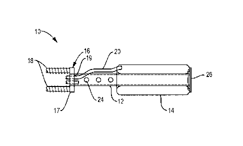
For example, Figure 11 depicts a similar embodiment to the
embodiment shown in Figure 1 but utilizes a threaded hollow rod
16 at the end of rod 12 instead of the washer and a flat plate 17
having a pair of threaded rods 18 secured thereto. In addition,
a breakaway fitting 22 is incorporated therein that permits the
feeder pipe 20 to be pulled from the adhesion anchor 14 after
filling rather than cutting the feed pipe(s). The breakaway
fitting may be made of a rubber tube, but is not limited thereto.
Figure 12 depicts a similar embodiment to the embodiment
shown in Figure 2 but utilizes breakaway fittings of the type
described above. Figure 13 depicts a similar embodiment to the
embodiment shown in Figure 3 but utilizes the threaded hollow rod
57 and breakaway fitting of the type shown in Figure 11. Figure
14 depicts a similar embodiment to the embodiment shown in Figure
21
CA 02838882 2013-12-09
WO 2012/174257 PCT/US2012/042484
4 but also uses the breakaway fittings described above. Figures
15 and 16 depicts similar embodiments to the embodiments shown in
Figures 5 and 6, respectively, but utilize the threaded hollow
rod and breakaway fittings described above.
I claim:
22