Note : Les descriptions sont présentées dans la langue officielle dans laquelle elles ont été soumises.
CA 02840089 2013-12-19
WO 2013/006560 PCT/US2012/045280
SCOOPING HYDRODYNAMIC SEAL
CROSS-REFERENCE TO RELATED APPLICATION
[0001] This application claims priority to U.S. Provisional Patent Application
Serial No.
61/503,815, filed July 1, 2011, the entire disclosure of which is incorporated
herein by reference.
BACKGROUND
1. TECHNICAL FIELD
[0002] The present disclosure relates generally to hydrodynamic face seals.
2. DESCRIPTION OF THE RELATED ART
[0003] Spiral groove lift-off seals (also known as hydrodynamic seals or
hydrodynamic face
seals) have been used successfully for many years in the industrial gas
compressor industry. The
physics of this type of seal is known and documented.
[0004] Generally, the seal assembly involves a high inlet fluid pressure
(e.g., high gas
density). The high fluid pressure may be located on either an outside diameter
of a seal assembly
or the inside diameter of a seal assembly, such as generally illustrated in
the cross-sectional
schematic seal assemblies of Figure 1A and Figure 1B, respectively. The seal
assembly can be
configured either way. The seal assemblies may comprise two rings where a face
of each ring is
adjacent to one another. A first ring may be a rotational member, also known
as a mating ring or
rotor, which may rotate about an axis that is generally shared by the two
components. A second
ring may be a stationary member, also known as a seal ring, and may be movable
only in an axial
direction. The first ring may contain a plurality of grooves on the face
adjacent to the second
ring as generally illustrated in Figures 1-3. The grooves, which may be spiral
in shape, are
grooved toward a low pressure side of the first ring. The grooves may have a
dam section where
the groove ends. A sealing effect around the dead ended grooves can provide a
compression of a
working fluid, such as gas, resulting in a pressure increase in the groove
region. The increase in
pressure can causes the faces to separate slightly, which can allow the
pressured fluid, such as
air, to escape the grooves. A steady state force balance between opening and
closing forces is
generally achieved at some determinable face separation gap. The seal may
operate in a non-
contact mode above some threshold rotational speed.
1
CA 02840089 2013-12-19
WO 2013/006560 PCT/US2012/045280
[0005] However, when employing conventional hydrodynamic groove technology for
the
purpose of producing a film riding seal (non-contacting) in sub-ambient
atmosphere, such as the
outside environment of an aircraft at cruising altitude, the ability for the
working fluid to enter
the shallow hydrodynamic grooves may be diminished due to the lower density
and rarefication
of the gas. As the actual volume of the working fluid, such as gas is reduced
with the decreasing
surrounding system pressure, the resulting hydrodynamic gas film between the
rotating mating
ring and the stationary seal ring can be significantly reduced. Thin
hydrodynamic air films may
not be entirely stable and may result in higher heat generation due, for
example, to intermittent
contact from transient conditions and high vicious shear of the fluid. With
respect to aerospace
applications, where high surface speed (e.g., 450 feet per second or faster)
between the rotating
mating ring and the stationary seal ring can be encountered, the aerodynamics
of the fluid may
further inhibit a working fluid from entering the hydrodynamic grooves.
[0006] Among other things, the present disclosure addresses one or more of the
aforementioned challenges.
SUMMARY
[0007] A hydrodynamic face seal may comprise a rotational first ring and a
stationary second
ring. The rotating first ring may include an inner face. The stationary second
ring may include
an inner face adjacent to the inner face of the rotating first ring. The inner
face of the rotating
first ring may include a groove having a fluid inlet portion and a
hydrodynamic force generating
portion. The fluid inlet portion of the groove may have a depth greater than
the hydrodynamic
force generating portion of the groove. A minimum depth of the fluid inlet
portion may be
configured to create a higher pressure than a surrounding pressure around the
rotating first ring,
while not generating a hydrodynamic or hydrostatic force in the fluid inlet
portion.
BRIEF DESCRIPTION OF THE DRAWINGS
[0008] The present invention will now be described, by way of example, with
reference to the
accompanying drawings, wherein like reference numerals identify like
components in the several
figures, in which:
2
CA 02840089 2013-12-19
WO 2013/006560 PCT/US2012/045280
[0009] FIGS. 1A and 1B are partial cross-sectional representations of a
conventional
hydrodynamic face seals.
[0010] FIG. 2 is a partial front view of the conventional hydrodynamic face
seal represented
in FIG. 1A.
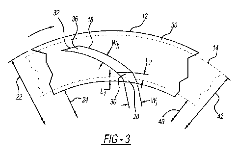
[0011] FIG. 3 is a partial front view of the conventional hydrodynamic face
seal represented
in FIG. 1B.
[0012] FIGS. 4A and 4B are cross-sectional views of hydrodynamic face seals
according to
embodiments of the present disclosure.
[0013] FIG. 5 is a partial front view of a hydrodynamic face seal according to
an embodiment
of the present disclosure.
[0014] FIG. 6 is an enlarged detail view of a scooping groove according to an
embodiment of
the present disclosure that generally illustrates a "chopper area" configured
to create disruption
within the film boundary layer and permit the redirection of a working fluid.
[0015] FIG. 7 is a graph generally illustrating seal face temperature
invariance with changing
shaft speeds.
DETAILED DESCRIPTION
[0016] Reference will now be made in detail to embodiments of the present
invention,
examples of which are described herein and illustrated in the accompanying
drawings. While the
invention will be described in conjunction with embodiments, it will be
understood that they are
not intended to limit the invention to these embodiments. On the contrary, the
invention is
intended to cover alternatives, modifications and equivalents, which may be
included within the
spirit and scope of the invention as defined by the appended claims.
[0017] Referring to Figures 1A, 1B, and 2, aspects of hydrodynamic face seals
10 are
generally illustrated. As depicted in Figure 1A, a hydrodynamic face seal 10
may comprise a
first ring 12 and a second ring 14. The first ring 12, which may also be
referred to as a mating
ring or rotor, may rotate about a commonly shared center line 16 with respect
to the first ring 12
and the second ring 14.
3
CA 02840089 2013-12-19
WO 2013/006560 PCT/US2012/045280
[0018] The first ring 12 may include a groove 18 or a plurality of grooves,
where each groove
18 of the plurality of grooves may have characteristics such as those
described in further detail
herein. The groove 18 may have an opening 20 along a surface (e.g.,
circumferential surface) of
the first ring 12, where the opening 20 is provided on an inner diameter 22
(e.g., as illustrated in
Figure 1B), or on an outer diameter 24 (e.g., as illustrated in Figure 1A).
Generally, the opening
20 of the groove 18 is provided on the high pressure side 26 of a face seal as
opposed to the low
pressure side 28 of the face seal. That is, if the high pressure side 26 is
associated with the outer
diameter 24 of the first ring 12, then the opening 20 may be provided on a
circumferential
surface of the outer diameter 24 of the first ring 12, such as generally
illustrated in Figure 1A.
Alternatively, if the high pressure side 26 is associated with the inner
diameter 22 of the first ring
12, then the opening 20 may be provided on the circumferential surface of the
inner diameter 22
of the first ring 12, such as generally illustrated in Figure 1B.
[0019] For some assemblies, the groove 18 may have a uniform depth along an
inner face 30
of the first ring 12. The depth of the groove 18 may be configured to generate
a hydrodynamic
force. Groove 18 depths may vary, for example, from 150 to 900 micro-inches.
The groove 18
may have a dam 32 (e.g. as generally shown in Figures 3, 4A, and 4B) where the
groove 18 ends
somewhere along the face of the first ring 12. The dam 32 can facilitate the
compression of a
fluid, such as a gas (e.g., air), which can result in a pressure increase in
the groove 18 of the first
ring 12. The increase in the pressure may cause the face of the first ring to
separate slightly
from a corresponding/mating surface of an adjacent component (e.g., second
ring 14). This
separation may be in the order of around 100 to 600 micro-inches. Seal leakage
occurs across
the dam 32 section may be relatively low because of the very small gap between
the sealing
faces.
[0020] The second ring 14, which may also be referred to as a seal ring, may
be stationary in
terms of rotation, but for applications may be permitted to move in the axial
direction ¨ e.g.,
along a center line 16. A face of the seal ring 14 adjacent the face of the
mating ring 12 may be a
flat lapped face, and may therefore be substantially flat. With embodiments,
the grooves 18 may
be placed on the second ring 14 as opposed to the first ring 12, although such
a configuration
may be less common in connection spiral groove configurations. With
embodiments, the
rotating first ring 12 having the grooves 18 is most often constructed of a
hard face coating or
material with respect to the stationary second ring 14.
4
CA 02840089 2013-12-19
WO 2013/006560 PCT/US2012/045280
[0021] With embodiments, to improve the volume of the fluid (e.g., gas)
entering the groove
18, such to create a film riding seal in a sub-ambient atmosphere, an inlet in
connection with
embodiments of this disclosure, such as described and illustrated below, may
be provided. With
reference to Figures 4-6, embodiments of a groove 18 that includes a fluid
inlet portion 34 and a
hydrodynamic force generating portion 36 are generally illustrated.
[0022] In an embodiment, a fluid inlet portion may be configured such that
opening 20 of the
groove 18 is provided on the circumferential surface of inner diameter 22 or
the outer diameter
24 of the first ring 12. However, the opening 20 of the groove 18 via the
fluid inlet portion 34
may also be exposed on the inner face surface 30 of the first ring 12 by
extending at least a
portion of the fluid inlet portion 34 in a radial direction beyond at least
one of the inner diameter
40 of the second ring 14 or the outer diameter 42 of the second ring 14, as
the case may be. With
such a configuration, either the inner diameter 40 of the second ring 14 is
larger than the inner
diameter 24 of the first ring 12 (i.e., exposing a portion of the inner face
30 of the first ring to the
high pressure side 26), or the outer diameter 42 of the second ring 14 is
smaller than the outer
diameter 22 of the first ring 12 (i.e., exposing a portion of the inner face
30 of the first ring to the
high pressure side 26). For example, in an embodiment, a portion of the fluid
inlet portion 34
may extend by at least a length (Li) of 0.01 inches in a radial direction
beyond at least one of the
inner diameter 40 of the second ring 14 or the outer diameter 42 of the second
ring 14.
[0023] In addition to the portion of the fluid inlet portion 34 being exposed
to the high
pressure side 26 acting as an opening 20, another portion of the fluid inlet
portion 34 may not be
exposed to the high pressure side 26, but rather, may be covered by the second
ring 14. For
example, in an embodiment, a portion of the fluid inlet portion 34 may extend
by at least a length
(L2) of 0.01 inches in an inward radial direction beyond at least one of the
inner diameter 40 of
the second ring 14 or the outer diameter 42 of the second ring 14, depending
upon the (0D/ID)
configuration employed.
[0024] As generally illustrated in Figures 4A and 4B, a hydrodynamic force
generating
portion 36 may be relatively shallow in depth compared to the fluid inlet
portion 34, both relative
to the inner face 30 of the rotating first ring 12. The hydrodynamic force
generating portion 36
can be configured to develop a hydrodynamic force to create lift-off during
operation. When the
first ring 12 is rotated at a particular speed, fluid enters the shallow
hydrodynamic force
CA 02840089 2013-12-19
WO 2013/006560 PCT/US2012/045280
generating portion 36 and the fluid is accelerated by the inertia of the first
ring 12 toward the
dam 32. The accelerated fluid may increase the pressure between the first ring
and the second
ring, and may produce a hydrodynamic air film. In an embodiment, the
hydrodynamic force
generating portion 36 depth may have a substantially consistent or constant
depth, and the depth
may be configured for an intended or anticipated rotational speed associated
with the first ring
12. For example and without limitation, in various embodiments, the depth of
the hydrodynamic
force generating portion 36 may range from about 150 micro-inches to 900 micro-
inches. If the
depth of the hydrodynamic force generating portion 36 is too great or too
small, the
hydrodynamic force may not be created or may not be sufficiently strong to
provide the
necessary separation between the faces of the rotating first ring 12 and
stationary second ring 14.
[0025] The fluid inlet portion 34 may be deeper than the hydrodynamic force
generating
portion 36 of the groove 18. With embodiments, the depth (d,) of the fluid
inlet portion 34 may
be sufficiently deep that it will not develop hydrodynamic or hydrostatic
force (e.g., lift-off
force) in that region. For example, in various embodiments, the depth (d,) of
the fluid inlet
portion 34 may be between about three times and about ten times deeper than
the depth (dh) of
the hydrodynamic force generating portion 36. In an embodiment, the depth (d,)
of the fluid inlet
portion 34 may be substantially constant and may transition into the
hydrodynamic force
generation portion 36 via a step 38, for example, as generally illustrated in
Figure 4B. In another
embodiment, the depth (d,) of the fluid inlet portion 34 may be sloped,
wherein the minimum
depth (d,,,n) of the fluid inlet portion 34 is closer to the transition step
38 from the fluid inlet
portion 34 to the hydrodynamic force generating portion 36, for example, as
generally illustrated
in Figure 4A. With such an embodiment, the minimum depth (d,,,n) of the fluid
inlet portion 34
may be between about three times and about ten times deeper than the depth
(dh) of the
hydrodynamic force generating portion 36. In various embodiments, the minimum
depth (d,,,n)
of the fluid inlet portion 34 may be between about 0.002 inches and about
0.025 inches.
[0026] In an embodiment, the width (W,) of the fluid inlet portion 34 may be
substantially the
same as the width (Wh) as the force generating portion 36, for example, as
generally illustrated in
Figure 3. In another embodiment, the width (W,) of the fluid inlet portion 34
may be greater
than the width (Wh) of the force generating portion 36, such as generally
illustrated in connection
with Figures 5 and 6. The wider width (Wh) of the fluid inlet portion 34 can
increase the length
(L,) of the fluid inlet portion 34. In embodiments, for example as generally
illustrated in Figures
6
CA 02840089 2013-12-19
WO 2013/006560 PCT/US2012/045280
and 6, the wider width of the fluid inlet portion 34 relative to the force
generating portion 36
can create a "chopper area" that may increase the amount or volume of
surrounding fluid that is
collected by the fluid inlet portion 34. Such a "chopper area" may have a
scooping radius (e.g.,
scooping radius 44) that is provided near an end of the fluid inlet portion 34
and, for some
embodiments, a transition step 38 may be configured to create disruptions in
the surround fluid
boundary layer.
[0027] With embodiments, the fluid inlet portion 34 may be configured to serve
as inlet
plenum for the hydrodynamic force generating portion 36. Rather than creating
hydrodynamic
or hydrostatic forces, the comparatively deeper fluid inlet portion 34 can be
configured to cause a
disruption of the fluid boundary layer and may create eddy currents within the
fluid inlet portion
34. This disruption caused by the fluid inlet portion 34 may enhance the
capture and redirection
of fluid in the high pressure side 26 to the hydrodynamic force generating
portion 36 of the
groove 18. That is, for embodiments, a disruption caused by the fluid inlet
portion 34 can
"supercharge" a comparatively relatively shallow hydrodynamic force generating
portion 36 of
the groove 18 to create a pressure significantly higher than that of the
system and/or ambient
pressure. As such, kinetic energy associated with the fluid inlet portion 34
of the first ring 12
may be transformed into potential energy in the form of compressed fluid
pressure within the
hydrodynamic force generation portion 34. This effect may be especially
beneficial in aerospace
applications where sub-ambient atmosphere conditions may occur. Utilizing some
of the
foregoing features may entrap more fluid and result in a more robust, thicker
and stiffer fluid
film between the first ring 12 and the second ring 14.
[0028] An embodiment of the present disclosure was tested in a simulated
working
environment. Results associated with the testing are included in the graph
shown in Figure 7.
The graph generally illustrates an anticipated seal face temperature
invariance with changing
shaft speeds with reference to the time elapsed. Various temperatures were
measured, including
the seal face temperature along plot line 48, the source air temperature along
plot line 50, and the
air/oil temperature along plot line 52. The shaft speed (measured in RPM) is
also shown along
plot line 46 illustrated in shaft speed versus the time elapsed and overlayed
upon the temperature
versus time elapsed for correlation of the temperature and shaft speed with
relation to the time
elapsed. As generally shown in Figure 7, the seal face temperature as
illustrated by plot line 48
remains fairly constant with any variation coinciding with the changes to the
shaft speed as
7
CA 02840089 2013-12-19
WO 2013/006560 PCT/US2012/045280
shown with plot line 46. This may be indicative of a sufficient film being
provided between the
seal rings. In a similar test using a conventional groove design, the seal
face temperature
increased more significantly for a given shaft speed, which may be indicative
of comparatively
less film being provided between the seal rings.
[0029] It is noted that the drawings are intended to illustrate various
concepts associated with
the disclosure and are not intended to so narrowly limit the invention. A wide
range of changes
and modifications to the embodiments described above will be apparent to those
skilled in the
art, and are contemplated. It is therefore intended that the foregoing
detailed description be
regarded as illustrative rather than limiting, and that it be understood that
it is the following
claims, including all equivalents, that are intended to define the spirit and
scope of this invention.
8