Note : Les descriptions sont présentées dans la langue officielle dans laquelle elles ont été soumises.
CA 02841593 2014-01-14
WO 2013/013260
PCT/AU2012/000867
- 1 -
VEHICLE BODY WITH A CURVED METAL PLATE FLOOR
Field of the Invention
The present invention relates to a vehicle body with a curved metal plate
floor.
The present invention relates particularly, although by no means exclusively,
to a
system for attaching a curved metal plate floor to a support frame of a load
carrying body of a
vehicle, such as a truck or a rail wagon.
The present invention is described hereinafter particularly in the context of
trucks and
truck bodies. However, it is emphasised that the present invention is not
limited to trucks and
truck bodies.
The floor attachment system of the present invention:
= Provides for easy installation and replacement of the floor.
= Allows for geometric variations between similar bodies.
= Provides more uniform transference of loads from the floor to the
structure of the body.
= Allows for varying the flexibility of the floor by design.
The floor attachment system of the present invention is particularly suited to
applications where;
= The truck body floors are subject to high impact loads during the truck
loading
operations.
= The truck body floors are subject to high abrasive wear conditions.
= Replacement or supplementary plating of the floor is required at least once
during the
operating life of the truck.
The above conditions typically arise in many applications of trucks used in
the mining
and quarrying industries. They also arise in other applications.
Background of the Invention
In most mining and quarrying applications, the floors of truck bodies are
constructed of
flat plates welded into the main structures of the bodies. In some more recent
truck bodies, the
floor plates are curved and welded into the main structures of the bodies.
The plate floors are welded to the sides of the body and to supporting beams
on the
.
underside of the floor plates. The floor plates are generally made from high
strength abrasion
resistant steels.
Mining truck bodies are typically very large. Payload capacities in excess of
100 tonnes
are common and in the largest trucks, payloads are greater than 350 tonnes.
During truck
loading operations, loads up to about 100 tonnes may be dropped several metres
directly onto
the floor of the truck body.
The material loaded into mining or quarrying trucks may vary widely in nature,
even in
the one mine. In one application it may be mostly large, hard, sharp cornered
and very
abrasive rocks. In another application the payload material may consist of
smaller and softer
CA 02841593 2014-01-14
WO 2013/013260
PCT/AU2012/000867
- 2 -
rocks that are very abrasive. In yet another application, the payload may have
a high proportion
of cohesive material that sticks to parts of the body and does not shed fully
from the body
during load tipping operations. Typically, a mining truck body and
particularly the floor must be
able to handle wide variations in rock impact, abrasive wear (mainly during
the load
tipping/dumping operations) and cohesiveness of the material carried.
Mining trucks are typically expected to have a working life of at least 60,000
operating
hours and during this time a single truck could experience about 300,000 load-
haul-dump
cycles.
The thickness of the steel truck body floors are typically in the range of 16
to 50mm.
Thicknesses greater than about 25mm are typically made up of a base plate and
a high
hardness wear resistant steel plate welded on top of the base plate. The top
plate may be
selectively placed rather than uniform over the whole area of the floor.
Sometimes, spaced
apart bars are used to reduce abrasive wear of the floor plate. Furthermore,
numerous large
supporting beams are required under these floor plates. These beams are
required to prevent
excessive bulging type permanent deformation of the floor when large rocks are
dropped onto
it.
Replacement or substantial repair of a truck body floor is typically required
at least
twice during the operating life of a mining truck. This repair work generally
necessitates
exchange of the truck body with a new or repaired body or that the truck spend
a lengthy time in
a workshop. The repair of truck body floors is a significant cost item for
many mining trucks.
In an effort to overcome the problems and costs associated with floors made
from flat
steel plates, the use of suspended rubber floors in truck bodies has also
become established in
the mining industry. In this case, the floor consists of a single thick piece
of rubber or a double
thickness of rubber sheeting supported by numerous cables spanning between
beams at the
base of the side sections of the body. The cables are made of multiple strands
of steel or
elastomeric material. The cables act to carry the vertical forces from the
load in the body via
tension in the cables similar to the way the cables of a suspension bridge
carry the loads from
the road section of a "suspension bridge".
The main advantages of the suspended rubber floor are:
= Moist clay containing cohesive materials are less likely to stick to the
body when it is
tipped to dump the load. =
= When worn out or badly damaged, the floor can be replaced relatively
quickly.
= The empty weight of the body is sometimes less than for an all steel body
of equivalent
capacity.
The improved shedding of cohesive (sticky) materials mainly results from the
flexing of
the rubber floor during load tipping operations.
CA 02841593 2014-01-14
WO 2013/013260
PCT/AU2012/000867
- 3 -
The disadvantages of the suspended rubber floor are:
= The initial purchase cost is higher than for an all-steel truck body.
= Frequent re-adjustment of the floor support cables is required (to adjust
for permanent
stretching that occurs).
= Intermittent and
un-predictable replacement of failed or severely damaged cables is
required.
= The rubber floor can be torn by large and sharp rocks.
= Replacement floors are expensive.
Because of the above difficulties, the applicant believes that the use of
suspended
rubber floors has been limited to less than 10% of all mining applications.
Their use is mainly
restricted to applications where the improved shedding of sticky materials is
very important
and/or where the elimination of supplementary wear resistant steel plating on
the floor of the
body is highly beneficial.
Analytical modelling work and mine site trials have shown that an alternative
to the
above-described floors is suspended curvedmetal (typically steel and
hereinafter described in
that context) truck body floors.
In any given application, a curved steel plate is supported only at the two
sides of a
truck body so that it curves down from and is suspended between the supporting
points at the
sides.
The suspended curved steel floor plate provides the general load containing
function
and acts as a tension member to transfer the vertical forces from the load on
the floor to tension
forces which are transferred into a support frame of the truck body. The
support frame
comprises beams at the base of the sides of the body. Because the suspended
curved steel
floor plate carries the forces arising from the payload primarily through
tension forces within the
plate, it has sometimes been referred to as a steel membrane floor. However,
in practice the
bending stiffness of the plate (arising from the thickness required to provide
a long life against
abrasive wear), the high variability in the placement of the loads Carried,
and in some cases,
eccentricity of the load transfer points on the edges of the floor, means that
the suspended
curved steel floor plate is also subjected to moderate bending loads. Unless
it is severely
overloaded, the suspended curved steel floor plate experiences only small
changes from its
initial shape.
Several edge-supported curved steel plate floors have performed successfully
in extended mine site trials during 1996 and 1997. These floor systems were
for a large rear
dump mining truck with a rated payload capacity of approximately 180 tonnes.
However, to date edge-supported curved steel plate floors have not been
commercially adopted for mining truck or other applications. The applicant
believes that the
main reasons for non-adoption of this technology are:
CA 02841593 2014-01-14
WO 2013/013260 PCT/AU2012/000867
- 4 -
= The cost of manufacturing the attachment system between the floor plate
and the
support frame of the body.
= The difficulty of achieving a good uniform contact between the abutment
bar on the
floor plate and the mating bar on the frame when replacement of the floor
plate is
required.
= Uncertainty about the ability of this floor to shed sticky materials.
The applicant has invented a system that attaches a curved metal plate floor
to a load
carrying body of a vehicle, such as a truck or rail wagon. The system is
described and claimed
in Australian patent 2006228988 in the name of the applicant and the
disclosure in the patent
specification of the patent is incorporated herein by cross-reference. The
system includes a
series of tensile members that are connected directly or indirectly at
opposite ends to (a) the
floor plate and (b) the body of the vehicle and these tensile members are at
least the principal
means for transfer of forces from the floor plate to the body. The patent
describes a particular
form of the tensile members.
,' The applicant has invented an alternative system that attaches a curved
metal plate
floor to a load carrying body of a vehicle, such as a truck or rail wagon. The
alternative system
is described herein.
The above description is not to be taken to be an admission of the common
general
knowledge in Australia or elsewhere.
Summary of Invention
In general terms, the present invention provides a system that attaches a
curved metal
plate floor to a load carrying body of,a vehicle, such as a truck or rail
wagon.
More particularly, the present invention provides a load carrying body for a
vehicle, and
the load carrying body includes a curved metal plate floor and a floor
attachment system that
attaches the floor to opposite sides of the body so that the floor is
suspended between the
sides, and the floor attachment system includes a plurality of tensile
members, each of which is
coupled at one end to one of the sides of the body of the vehicle and at the
other end to a side
edge of the floor, with each tensile member having a .coupling element that is
retained within (a)
a recess in the edge of the floor or (b) an opening that extends-through the
floor from an upper
surface to a lower surface of the floor, with the tensile members being at
least the principal
means for transferring forces from the floor to the remainder of the body.
The term "tensile members" in the context of the present invention is
understood to
mean members that allow movement of the floor relative to the remainder of the
vehicle body by
a mechanism of tension loading and unloading of the members. This is a
different mechanism
to that which operates where there is rigid clamping that prevents any
movement between the
edges of the floor and the adjacent parts of the vehicle body.
CA 02841593 2014-01-14
WO 2013/013260 PCT/AU2012/000867
- 5 -
The term "principal means" in the above reference to "the tensile members
being at
least the principal means for transferring forces from the floor to the
remainder of the body' is
understood herein to mean that, whilst there may be other elements that
transfer forces from
the floor to the remainder of the body, the tensile members are intended to
provide at least
60%, typically at least 70%, preferably at least 80%, and more preferably all,
of the force
transfer between the floor and the remainder of the body.
The coupling element and the recess/opening may be formed to allow swivelling
movement of the coupling element in the recess/opening to accommodate
misalignment of the
floor and the body in two mutually perpendicular directions that can occur as
a consequence of
varying the load on the floor and/or manufacturing variations in alignment.
The resultant
swivelling movement of the coupling element relative to the floor in the two
mutually
perpendicular directions meets two important requirements. One requirement is
to
accommodate geometry changes as a consequence of varying loads on the floor.
Another
consequence is to accommodate changes of alignment during manufacture. By way
of
example, these manufacturing alignment issues may be a result of variations in
manufacturing
dimensions or overlapping of adjoining plates making up a floor.
The coupling element and the recess/opening may be formed to accommodate
misalignment of the floor and the body in two mutually perpendicular
directions that can occur
as a consequence of varying the load on the floor and/or manufacturing
variations in alignment.
The coupling element and the recess/opening may be formed to accommodate
misalignment of the floor and the body in a direction that is perpendicular to
the plane of the
floor at the side edge of the floor that can occur as a consequence of varying
the load on the
floor and/or manufacturing variations in alignment.
The coupling element and the recess/opening may be formed to accommodate
longitudinal misalignment of the floor and the body that can occur as a
consequence of varying
the load on the floor and/or manufacturing variations in alignment.
Each side of the body may include a longitudinal beam and the coupling element
and
the recess/opening may be formed to accommodate longitudinal misalignment of
the floor and
the longitudinal beams of the body that can occur as a consequence of varying
the load on the
floor and/or manufacturing variations in alignment.
The terms "longitudinal misalignment of the floor and the body and
"longitudinal
misalignment of the floor and the longitudinal beams of the body" are
understood herein to
mean misalignment in a forward-rearward direction of the body.
The tensile member may comprise an elongate element.
The coupling element and the elongate element may be integrally formed.
The coupling element and the elongate element may be separate elements that
can be
coupled together.
CA 02841593 2014-01-14
WO 2013/013260 PCT/AU2012/000867
- 6 -
The coupling element may be a formation, such as a nut, that is received in
and
retained within the recess in the edge of the floor.
The coupling element may include top and bottom flanges that locate the
element in
relation to top and bottom surfaces of the floor and retain the element in the
recess.
The coupling element may include at least one abutment surface that is adapted
to
engage a corresponding abutment surface of the floor and allow swivelling
movement of the
coupling element in the recess.
The abutment surface may be curved about two mutually perpendicular axes.
The recess may be in the form of a notch.
The recess may be in the form of a cut-out section.
The cut-out section may be a key-hole shape.
The coupling element may be a clevis and clevis pin assembly, with the clevis
pin extendingthrough the opening in the floor.
The openings may be at least 1rnrn inboard of the closer side edge of the
floor.
The tensile members may be releasably coupled to one or both of the body and
the floor to allow replacement of the floor.
The tensile members may be releasably coupled to one or both of the
longitudinal
beams of the body and the floor to allow replacement of the floor.
The tensile members may have an adjustable-length.
The tensile members may apply a tension load to the floor plate at or close to
a
centre-line of the thickness of the plate. The tensile members may apply a
tension load to the
floor plate along a line of action that is within 10% of the thickness of the
floor plate relative to
the centre-line of the thickness of the plate.
The tensile members, and typically the tensile elements, may have an
unsupported length that is significantly greater than their diameter. For
example, the
unsupported length may be at least 2 times, typically at least 4 times and
more typically at least
6 times the diameter of the member. The long unsupported length allows flexure
of the tensile
members to help accommodate any changes of alignment that may occur and it
also reduces
the angle of swivelling required at both ends of the tensile members. Another
advantage is that
it also adds to the flexibility of the floor system. A long unsupported length
of the tensile
members also increases the vertical movement of the floor plate as the
vertical loading on the
floor plate changes. Increased vertical movement of the floor plate assists
with freeing of sticky
materials that would otherwise accumulate around the corners of the load
carrying body.
The present invention also provides a vehicle that includes the above-
described load carrying body having a curved metal plate floor and a floor
attachment system .
that attaches the floor to the remainder of the body.
The floor may comprise a plurality of the above-described recesses at spaced
intervals
along the side edges of the floor.
The floor may comprise a plurality of the above-described openings that extend
through
CA 02841593 2014-01-14
WO 2013/013260 PCT/AU2012/000867
- 7 -
the floor from the upper surface to the lower surface of the floor at spaced
intervals along the
side edges of the floor.
The openings may be at least 1 mm inboard of the closer side edge of the
floor.
The present invention also provides a curved metal plate floor that includes a
plurality of the above-described recesses at spaced intervals along the side
edges of the floor.
The present invention also provides a curved metal plate floor that includes a
plurality
of the above-described openings that extend through the floor from the upper
surface to the
lower surface of the floor at spaced intervals along the side edges of the
floor.
The openings may be at least 1mm inboard of the closer side edge of the floor.
Some of the advantages of the invention are:
= There are no separate welded-on abutment or anchorage plates on the
curved metal
floor.
= Lower manufacturing costs.
= Can use higher hardness (more wear resistant) floor plates in some
applications (due to
no welding requirement).
= The forces from the tensile members act on or very close to the centre-
line of the plate
thickness.
= Thinner floors become possible in some applications (due to negligible
bending
moments induced by the tensile members and the elimination of welds that would
require lower operating stress levels).
= The system can work with the line of action of the tensile member
significantly off
perpendicular to the edge of the floor (in both the vertical and longitudinal
directions).
= Allows the use of overlapping floor segments (rather than butt welding
the segments
together) ¨ with a linear arrangement for the outer ends of the tensile
members.
= Allows changing the radius of curvature of the floor across the length of a
floor segment
(to make a partial conical section).
Brief Description of the Drawings =
The present invention is described further by way of example with reference to
the
accompanying drawings, of which:
Figure 1 shows the principle of the edge-supported curved metal plate floor,
as
described above;
Figure 2 is a side elevation of a truck having a truck body in a carry
position, with the
truck body including one embodiment of a system for attaching the curved metal
plate floor of
the body to the remainder of the body in accordance with the present
invention;
Figure 3 is a side elevation of the truck shown in Figure 2 with the truck
body in an
unload position;
the truck shown in Figures 2 and 3;
Figure 4 is a top plan view of the truck body of the truck shown in Figures 2
and 3;
CA 02841593 2014-01-14
WO 2013/013260 PCT/AU2012/000867
- 8 -
Figure 5 is a cross-section along the line 5-5 of Figure 4, with the figure
showing the
floor attachment system and the arrangement of the beam structure that
supports the floor of
the truck body shown in Figures 2 to 4;
Figure 6 is a detailed view of the region described by the circle marked "B"
in Figure 5,
with the figure showing the floor attachment system of the truck body shown in
Figures 2 to 4;
Figure 7 is a partial top plan view of the floor of the body that shows the
shape of the
recesses in the side edges of the floor that forms part of the floor
attachment system of the
truck body shown in Figures 2 to 4;
Figure 8 is a detailed view of the region described by circle "C" in Figure 7;
Figure 9 is a partial perspective view from above that illustrates in a
simplified form the
floor attachment system of the truck body shown in Figures 2 to 4;
Figure 10 is a partial perspective view from below that illustrates in a
simplified form the
floor attachment system of the truck body shown in Figures 2 to 4;
Figure 11 is a detailed view of the region described by the circle marked "A"
in Figure 4,
with the figure showing the floor attachment system of the truck body shown in
Figures 2 to 4;
Figure 12 is a cross-section view along line 12-12 in Figure 11;
Figure 13 is a detailed view of the region described by the circle "C" in
Figure 12;
=
Figure 14 provides three views of the coupling element that forms part of the
floor
attachment system of the truck body shown in Figures 2 to 4;
Figure 15 is a partial view from above that shows the upper part of the system
for
retaining the coupling elements of the floor attachment system of the truck
body shown in
Figures 2 to 4;
Figure 16 is a partial perspective view from above that shows more completely
the
" upper part of the system for retaining the coupling elements of the
floor attachment system of
the truck body shown in Figures 2 to 4;
Figure 17 is a partial perspective view from below that shows more completely
the
lower part of the system for retaining the coupling elements of the floor
attachment system of
the truck body shown in Figures 2 to 4;
Figure 18 is a perspective view of another, although not the only other,
embodiment of
a system for attaching a curved metal plate floor of a body of a vehicle to
the remainder of the
body in accordance with the present invention;
Figure 19 provides two diagrammatic views showing more detail of the coupling
system
shown in Figure 19; and
Figure 20 illustrates how the coupling element shown in Figures 18 and 19 can
provide
articulation in both the longitudinal direction and the upward/downward
direction relative to the
edge of the floor of the truck body shown in Figures 2 to 4.
CA 02841593 2014-01-14
WO 2013/013260 PCT/AU2012/000867
- 9 -
Description of the Embodiments Shown in the Drawings
The following description of the present invention is in the context of trucks
and truck
bodies. As noted above, the present invention extends to any type of vehicle.
Figure 1 shows the principle of an edge-supported curved steel plate floor 10
of a truck
body. The floor 10 shown in the Figure, which is typically 12-50mm thick and 4-
10 tonnes in
weight, is rolled to a constant or varying radius R. The floor 10 is supported
at the side edges
12 of the floor 10 only. The edge forces F that are generated by the floor 10
act tangentially to
the edges of the floor 10. Because of the curvature of the floor 10, the
tangent line is at an
angle (0) above the horizontal. The vertical component of the tangential
forces (F x sine)
balances the weight of the floor 10 plus the weight of the payload (W) carried
by the floor 10.
In most applications and particularly in mining truck applications, it is
desirable to have
the largest practical radius of curvature for the floor plate so that the
centre of gravity for the
payload is as low as possible because increasing the height of the centre of
gravity for the
payload reduces the stability of the truck and increases the stresses on many
of the truck
components during cornering, braking etc.
The edge-supported curved steel plate floor 10 provides the potential for:
= A lower empty truck weight without increasing the manufacturing cost for
the truck.
= Rapid, low cost replacement of the truck body floor.
= Improved shedding of cohesive (sticky) materials compared to the
conventional rigid all
steel bodies.
The truck shown in Figures 2 and 3 is suitable for use for hauling mined ore
and waste materials in open-pit mines. The mined ore may be any type of ore,
such as iron ore
and coal.
The truck includes a wheel-mounted chassis, a cabin, and a truck body,
generally
identified by the numeral 2 for containing mined material. The body 2 has
opposed sides, a
front end, and a rear end. The body 2 is supported on the truck chassis for
pivoting movement
between the carry and unloading positions shown in Figures 2 and 3
respectively. The present
invention is not confined to the particular configuration of the truck shown
in Figures 2 and 3.
The body 2 includes an array of transverse beams 30 and longitudinal beams 31
and
32 that are welded together and define a support frame for the body 2. The
inner pair of
longitudinal beams 31 transfers the loads from the body 2 to the chassis of
the truck via pivot
couplings on the beams and the chassis and via support pads 27 between the
body and the
chassis of the truck.
The body 2 also includes side walls 28 that extend upwardly from the outermost
longitudinal beams 32, a front wall 34, and a canopy 36. The side walls 28,
the front wall 34
and the canopy 36 are made from plate steel.
= The body 2 also includes a curved metal plate floor 10 that is suspended
between the
opposite sides of the body 2.
The body 2 also includes one embodiment of an attachment system for the curved
CA 02841593 2014-01-14
WO 2013/013260 PCT/AU2012/000867
- 10 -
metal plate floor 10 in accordance with the present invention. The system
couples the floor 10
to the outermost longitudinal beams 32 of the body 2 and thereby suspends the
floor 10
between the sides of the body 2. The arrangement of the transverse and
longitudinal beams is
shown in more detail in Figures 4 and 5. The attachment of the floor 10 to the
outermost
longitudinal beams 32 is shown in Figures 5 and 6. The floor 10 is made from
steel plate that
has been rolled or otherwise formed to have a prescribed radius R. This radius
may be
constant or varying across the width of the floor 10. The radius R may also
vary along the
length of the floor. The floor 10 includes a top surface 60 and a bottom
surface 62. The floor 10
includes a plurality of recesses 48 at spaced intervals along side edges 40 of
the floor 10
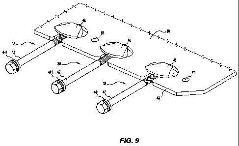
(Figures 7 and 9 to 11).
As is described in more detail below, the recesses 48 form part of one
embodiment of a
floor attachment system in accordance with the present invention.
With particular reference to Figures 7 and 8, each recess 48 is in the form of
a key-hole
that has a first throat section 50 that extends inwardly from a side edge 40
of the floor 10 and a
larger main section 52. The main section 52 is defined in part by a pair of
abutment surfaces 56
of the floor 10 that extend outwardly from the throat section 50 and inwardly
from the side edge
40 and define a curved surface ¨ which is a concave surface as viewed from
within the main
section 52. The abutment surfaces 56 are approximately perpendicular to the
top and bottom
surfaces 60, 62 ¨ see Figure 13.
With reference to Figures 6 and 9 to 11, the embodiment of the floor
attachment system shown in these figures also includes a series of tensile
members generally
identified by the numeral 38 that are coupled at one end to the outermost
longitudinal beams 32
and at the other end to a side edge 40 of the floor 10, with the tensile
members being at least
the principal means for transferring forces from the floor to the body. The
tensile members 38
apply a tension load to the floor 10 at or near to a centre-line of the
thickness of the floor 10
between the top and bottom surfaces 60,62 of the floor 10.
Each tensile member 38 comprises (a) an elongate element 42 in the form of a
bolt
= having a head 44 at one end and a thread at the other end and (b) a
separate coupling element
46 in the form of a nut with a threaded hole 76 that can receive the threaded
end of the
= 30 elongate element 42.
The coupling element 46 is formed so that it can be retained within the main
section 52
of the recess 48 in the side edge 40 of the floor 10.
The coupling element 46 and the recess 48 are formed to accommodate
misalignment
of the floor 10 and the body 2 in two mutually perpendicular directions that
can occur as a
consequence of varying the load on the floor 10 and/or manufacturing
alignment. One direction
is a direction perpendicular to the plane of the floor 10 at the side edges 40
of the floor 10 and
the other direction is a longitudinal direction of the body 2. The top surface
60 or the bottom
surface 62 of the floor 10 at the side edges 40 of the floor 10 are understood
herein to be the
plane of the floor 10. Misalignment in the direction perpendicular to the
plane of the floor 10 is
CA 02841593 2014-01-14
WO 2013/013260 PCT/AU2012/000867
- 11 -
provided by the radius 141 on the abutment surfaces 74 on the coupling element
46 rolling in
the vertical direction on the corresponding surface in the recesses 48 in the
floor 10.
Misalignment in the longitudinal direction of the body 2 is provided by
rotational sliding between
the radius 143 on the coupling element 46 and the radius 56 of the abutment
surfaces in the
recess 48 in the floor 10.
With particular reference to Figures 5, 6 and 12, each outermost longitudinal
beam 32
is a hollow box section that has aligned openings in the outer and inner side
walls 80, 82
respectively of the beam. Each tensile member 38 can be positioned so that the
elongate
element 42 extends through the openings, with the head 44 engaging the wall 80
via a
swivelling type washer assembly 441.
With particular reference to Figures 13 and 14, each coupling element 46 has a
pair of
top and bottom flanges 70, 72 that locate the coupling element 46 in relation
to the top and
bottom surfaces 60, 62 of the floor 10 and retain the coupling element in the
recess 48. Each
coupling element 46 also includes a pair of abutment surfaces 74 (Figure 14)
between the
flanges 70, 72. The abutment surfaces 74 engage the abutment surfaces 56 of
the floor 10.
The abutment surfaces 74 are curved surfaces, with the curves extending
outwardly and
rearwardly in relation to the internally threaded hole 76 in the coupling
element 46. The
= abutment surfaces 74 are also convex between the top and bottom flanges
70, 72 of the
coupling element 46¨ see Figure 14. Hence, each abutment surface 74 of the
coupling
element 46 is curved about two mutually perpendicular axes.
= The curved surfaces of the abutment surfaces 56 of the floor 10 and the
abutment
surfaces 74 of the coupling elements 46 can accommodate limited relative
Changes of
alignment between the coupling elements 46 and the floor 10 in two directions.
This movement
can be described as swivelling movement. This swivelling movement allows
limited movement
of the floor 10 relative to the remainder of the body 2 in two directions
without imposing
unacceptable bending on the elongate elements 42. In the context of a truck
body 2 located on
a truck in a carry position, one of these directions can be described as a
forward/rearward (i.e.
longitudinal) direction and the other direction can be described as an
upward/downward
direction.
, In use, the following sequence of steps suspends the floor 10 in a
required position in
the remainder of the body 2. A first step is to position each coupling element
46 in the main
section 52 of a recess 48 of the floor 10 as shown in Figure 15. The main
section 52 is slightly
larger than the coupling element 46 to allow the coupling element 46 to be
located in the main
section 52. Once a line of the coupling elements 46 is located in respective
recesses 48, top
and bottom retaining plates 86 and 88 are positioned close to the inner face
131 of the coupling
elements 46 and retain the coupling elements 46 in. the recesses 48, with the
coupling elements
46 being biased outwardly towards the side edge 40 of the floor so that the
retaining flanges 70,
72 of the coupling elements 46 are located above and below the top and bottom
surfaces 60,
62 of the floor 10 as shown in the figures. The retaining plates 86 and 88 are
held to the floor
CA 02841593 2014-01-14
WO 2013/013260 PCT/AU2012/000867
-12-
by a plurality of bolts 90 that extend through openings in the retaining
plates 86 and 88 and
also through openings 87 in the floor 10. The profile of the top and bottom
retaining plates 86
ad 88 and the positioning of the retaining plates relative to the coupling
elements 46 allows
sufficient clearance for the before described swivelling movement of the
coupling elements 46
5 relative to the floor 10. The retaining plates 86 and 88 may also retain
a high viscosity grease
around the enclosed parts of the coupling elements 46. The assembly of the
floor 10 and the
coupling elements 46 is then lifted into the body 2 and is safely supported in
the required
position in the body 2. At this point, the elongate elements 42 are inserted
through the
openings in the walls 80, 82 of the outermost longitudinal beams 32 and the
threaded ends are
10 rotated into the threaded openings of the coupling elements 46 (Figure
6, 16 and 17). A
required tensioning of the elongate elements 42 and the coupling elements 46
is applied to
properly suspend the floor 10 in position in the body 2. The height of the
floor 10 relative to the
rest of the body 2 is controlled by contact between the upper retaining plate
86 and the bottom
surface of an abutment plate 89 attached to the outermost longitudinal beam 32
(see Figure 6).
At this point, the external support for the floor 10 can be removed, and the
assembly of the floor
10 in the body 2 is complete.
The embodiment of the floor attachment system shown in Figures 18, 19 and 20
is
similar to the embodiment shown in Figures 5 to 17 in that the system:
(a) includes elongate elements 42 that are at least the principal means for
transferring
forces from the floor 10 to the body 2, and
(b) allows swivelling movement, i.e. multiple direction movement, between the
coupling
element 182 and the floor 10 of the body 2.
Instead of the recesses 48 of the embodiment described in relation to Figures
5 to 17,
the system shown in Figures 18, 19 and 20 includes a plurality of openings 92
that extend
through the floor 10 from the top surface 60 to the bottom surface 62 of the
floor 10.
The system also includes tensile members 38 that include (a) the above-
described
elongate elements 42 and (b) coupling elements 46 in the form of clevis,
clevis pin and bushing
assemblies. Each assembly comprises a clevis 96 that has a threaded opening
for the elongate
element 42, a clevis pin 98, and a barrel shaped bushing 102 with the clevis
pin 98 and the
barrel shaped bushing 102 extending through an opening 90 in the floor 10.
The clevis pin 98 may be in the form of a threaded bolt. The clevis pin
engages with
the sides of openings 92 that extend through the floor 10 via a barrel shaped
bushing 102. The
barrel shape of the bushing allows rotation of the coupling clevis 96 relative
to the floor 10 in
both the longitudinal direction and the upward/downward direction (Figure 20).
=
CA 02841593 2014-01-14
WO 2013/013260 PCT/AU2012/000867
- 13 -
The cylindrical shaped elastomeric seals 104 centralise the coupling clevis 96
in the
vertical direction relative to the floor 10. The compliance of the elastomeric
material of .the seals
allows the coupling clevis 96 to rotate relative to the floor 10 in the
upward/downward direction.
The elastomeric seals also retain lubricating grease in the space around the
barrel shaped
bushing 102 and prevent the ingress of abrasive materials into this space.
Many modifications may be made to the preferred embodiments as described above
without departing from the spirit and scope of the present invention.
By way of example, whilst the embodiment of the coupling member shown in
Figures 5
to 17 is described as comprising a separate elongate and coupling elements 42,
46, it is noted
that the present invention is not so limited and extends to arrangements in
which the two
elements 42, 46 are integrally formed.