Note : Les descriptions sont présentées dans la langue officielle dans laquelle elles ont été soumises.
CA 02841615 2014-01-13
ft. 1
DEVICE FOR OBTAINING ELECTRICAL ENERGY FROM WATER
POWER
The invention relates to an installation for generating electrical energy from
hydropower,
comprising a drive arrangement which revolves around two deflection elements
distanced to one
another and which can be driven by hydropower in a revolving direction, with a
load section running
along a gradient, wherein the drive arrangement comprises a plurality of
gravitational pressure
transmission units which are arranged one after the other in the revolving
direction, are distanced to
one another and are each with an onflow element, further comprising a
generator for generating
electrical energy from the revolving drive arrangement.
The invention moreover also relates to a method for operating such an
installation.
A multitude of devices are known, which utilise the potential drop of water or
its kinetic
energy, in order to generate electrical energy therefrom. In this context, one
basically differentiates
between two installation types.
According to a first installation type, the kinetic energy of the onflowing
water is utilised, in
order to drive a generator for electricity production with this. For this,
onflow elements such as
turbine blades are provided, onto which water flows and which are set in
motion by way of this.
Hydropower installations of the first type are to be found in river power
stations or storage power
stations. The middleshot-undershot waterwheel is also driven in this manner.
According to a second installation type, it is not primarily the kinetic
energy of the onflowing
water, but rather its potential energy which is released whilst undergoing a
potential drop which is
utilised. This means that according to this principle, the gravitation force
of the water acting on the
onflow element drives an onflow element. This principle is utilised for
example with an overshot
waterwheel.
EP-A-1 731 756 for example describes a hydropower installation, with which the
potential
energy of water is utilised for generating electrical energy. The installation
comprises a hydropower
unit with a vertical shaft, and a generator connected to the hydropower unit.
Blades which receive a
certain volume of water are arranged in the shaft in a manner fastened on a
chain. The chain and, via
this, a generator are driven by the weight of the water bearing on the blades.
The installation is
CA 02841615 2014-01-13
a. 2
however comparatively inflexible with regard to its application possibilities,
since these can only be
carried out in combination with a vertical shaft.
WO 2011/041918 likewise describes an installation for generating electrical
energy from
hydropower. This comprises a revolving drive chain with a load section and
return section. The
drive chain is led in a revolving direction around two deflection elements
which are arranged
horizontally as well as vertically offset to one another. The drive chain
comprises a plurality of
onflow elements which are arranged one after the other in the revolving
direction and are distanced
to one another. The onflow elements in each case form part of a chain link of
the drive chain. The
onflow elements on the side of the load section engage into an inclined water
guidance channel and
with the lateral channel walls as well as the channel base form water
receiving compartments. The
individual water receiving compartments in the run-in region accommodate a
certain volume of
water which is not let out of the water receiving compartment again until in
the outlet region.
Moreover, the installation comprises a generator for generating electrical
energy from the
revolving drive chain. The water is fed into the water guidance channel at a
run-in region which is
situated at a higher level, wherein the blades immersing into the water
guidance channel hold back
the flowing-in water, in the formed water receiving compartments. The blades
are driven by the
force weight of the water, by which means the water is led in the receiving
compartments along the
water guidance channel to an outlet opening which is situated as a lower
level. The described
solution has the disadvantage that the guiding of the blades in the water
guidance channel is quite
imprecise, so that the receiving compartments in the movement direction are
too permeable with
regard to the entrained water, and a part of the entrained water runs down the
water guidance
channel to the outlet region, whilst not being utilised.
It is therefore the object of the present invention, to improve the guiding of
the onflow
elements in the water guidance channel as well as the water guidance
generally, in order not least to
increase the efficiency of the installation.
The object is achieved by the features of the independent claim. Further
preferred
embodiments and further developments of the invention are to be deduced from
the dependent
patent claims. Thereby features of the method claims with regard to context
can be combined with
the device claims and vice versa.
The invention is thus characterised in that the gravitational pressure
transmission units
comprise guide elements, and the installation comprises guide means along the
load section, in
which guide means the gravitational pressure transmission units are
displaceably arranged in a
CA 02841615 2014-01-13
3
manner such that the gravitational pressure transmission units at least in the
region of the load
section are guidable between the two deflection elements.
The gravitational pressure transmission units are preferably positively guided
(restraint-
guided) via the guide elements guided in the guide means. "Positively guided"
means that the guide
elements are guided via the guide means at least in two spatial directions
with respect to a three-
dimensional orthogonal or polar coordinate system. These two spatial
directions are preferably
opposite to one another.
The gravitational pressure transmission units are preferably designed of
several parts. Thus
the guide elements and onflow elements are preferably designed as separate
components.
The two deflection elements are preferably arranged offset to one another,
horizontally as
well as vertically.
The installation according to the invention moreover comprises a water
guidance channel
which runs along the descent or a slope, wherein the onflow elements of the
gravitational pressure
transmission units, in the region of the load section run transversely to the
water guidance channel
and engage into this.
In each case, two adjacent onflow elements, in the region of the load section,
together with
the channel walls form a water-receiving compartment which is co-moved along
the water guidance
channel. The onflow element which is subjected to onflow by water in the run-
in region, thus serve
as a compartment separation element.
The individual water receiving compartments in the run-in region accommodate a
certain
volume of water which is not released from the water receiving compartment
again until in the outlet
(discharge) region.
The water guidance channel, or also called trough, preferably forms a U-shaped
cross-
sectional profile with a channel base and two channel side walls. The onflow
elements are usefully
led in the water guidance channel in a contact-free manner.
Since the position of the onflow elements relative to the water guidance
channel can be fixed
in a very accurate manner thanks to the positive guiding by the guide means,
the onflow elements
only have very small distances to the adjacent channel walls. The gap distance
can e.g. be merely 1
to 5 mm, in particular merely 2 to 3 mm.
CA 02841615 2014-01-13
4
An upper deflection element is preferably arranged in the run-in region, in
which the water is
admitted into the water guidance channel. A lower deflection element is
preferably arranged in an
outlet region, in which the water is released out of the water receiving
compartments. The
gravitational pressure transmission units are led back along the return
section out of the outlet region
into the run-in region. The return section preferably runs above the load
section. The return section is
preferably led parallel to the load section.
The water in the run-in region can flow in parallel to the revolving
direction, thus frontally
onto the onflow elements and into the water guidance channel. With certain
configurations however,
the water in the run-in region, seen in the revolving direction, preferably
flows in laterally obliquely
up to the onflow elements and into the water receiving compartments. A
combination of a frontal
and laterally oblique onflow is also possible.
The onflow elements are preferably designed as wall elements, in particular as
blade-like
wall elements. The onflow elements can e.g. comprise side walls which e.g. on
both sides are curved
oppositely to the movement direction of the drive arrangement and which form a
blade-like receiver.
The run-in procedure of the water is optimised by way of such a shaping.
The onflow elements are preferably designed in a lightweight construction
manner. I.e., the
wall elements are preferably designed in a thin-walled manner. The onflow
elements are preferably
manufactured of a lightweight construction material, such as aluminium or
plastic, in particular fibre
composite material. The onflow elements can also be designed of an aluminium-
plastic-aluminium
composite plate element.
The width (longitudinal extension transverse to the water guidance channel) of
the onflow
element is usefully significantly larger than its depth or height. Thus the
ratio of the width to depth is
preferably 2:1 or greater, and in particular 3:1 or greater or even 4:1 or
greater.
It is also conceivable for the ratio of width to height to lie in a similar
region. Thus this ratio e.g. can
be 2:1 or greater and in particular 3:1 or greater or even 4:1 or greater.
Thanks to the specified length ratios, better filling results can be achieved
for the water
receiving compartments. This amongst other things is due to the fact that the
width of the water feed
in the run-in region is comparatively large in comparison to the depth of the
forming water receiving
compartments, which permits a rapid and accordingly high filling of the water
receiving
compartments. The width of the onflow elements can e.g. be about 1000 mm,
whilst the depth is
about 250 mm.
CA 02841615 2014-01-13
The wall-like onflow elements each preferably have at least one stiffening
element, also
called reinforcement element, so that they obtain an adequately high
stiffness, in order to withstand
the water pressure. Preferably, the onflow elements each comprise at least two
stiffening elements
which are arranged off-centred or laterally. The stiffening elements are
preferably arranged in a
lateral end region of the onflow elements. The stiffening elements can e.g. be
designed as stiffening
ribs or stiffening walls or transverse walls.
The stiffening walls can be closed or provided with openings. The stiffening
walls in
particular can be designed as an open lattice construction. The transverse
walls preferably run
parallel to the movement direction of the drive arrangement. The transverse
walls can be attached
onto the onflow element via a non-positive fit connection, a positive fit
connection or material fit
connection. A combination of the mentioned connection types is also possible.
The transverse walls
can in particular be stuck on, bonded or welded.
The guide means can be designed as guide rollers or sliding elements. The
sliding elements
can be sliding blocks.
The term "rollers" includes all bodies which are suitable for rolling over a
surface. Wheels
and balls for example are also included thereunder.
The positive guidance (restraint-guide) of the gravitational pressure
transmission units can be
designed in various manners with regard to the arrangement and design of the
guide elements and
the guide means.
Thus the guide means for example can comprise at least one guide rail which
forms at least
one running surface or sliding surface for the guide elements.
Moreover, the guide means can also be formed by a tubular channel, in which
the
gravitational pressure transmission units are displaceably guided. The tubular
channel in the load
section at the same time also forms the water guidance channel. The guide
element here for example
can be formed by the onflow element itself.
If the guide means comprise guide rails, then the gravitational pressure
transmission units
according to a first variant in each case comprise two guide elements which
are arranged laterally of
the onflow element seen in the revolving direction. The installation moreover
in the load section
comprises two guide rails which are each arranged laterally on the water
guidance channel, in
CA 02841615 2014-01-13
6 -
particular in the channel side walls, wherein the guide elements along the
load section are led in the
guide rails.
According to a first sub-variant, the guide elements, with respect to the
closed revolving
path, are arranged laterally on the radially outwardly lying end section of
the onflow element. The
guide rail is arranged laterally in the region of the end section of the water
guidance channel which is
towards the base.
According to a second sub-variant, the guide elements with respect to the
closed revolving
path are arranged laterally between the radially outwardy lying and inwardy
lying end sections of the
onflow element. The guide rails are arranged laterally in the region between
the end section which is
towards the base and the opening-side end section, of the water guidance
channel, in or on the
channel side wall.
According to a third sub-variant, the guide elements with respect to the
closed revolving path
are arranged laterally on the radially inwardy lying end section of the onflow
element. The guide
rails are arranged laterally in the region of the opening-side end section of
the water guidance
channel.
According a second variant, the installation comprises a guide rail arranged
above the water
guidance channel. The gravitational pressure transmission unit moreover
comprises at least one
guide element which is arranged above the onflow element and which in the
region of the load
section is led the guide rail.
The design of the drive arrangement can be likewise different with regard to
the functional
interaction between the individual gravitational pressure transmission units.
According to a first embodiment of the invention, the elements are then not
connected to one
another, i.e. are designed independently of one another with regard to
connection technology.
The drive arrangement according to this embodiment is driven by the
transmission of push
forces between the gravitational pressure transmission units. The
gravitational pressure transmission
units are designed as push bodies and comprise force transmission elements for
transmitting push
forces from a gravitational pressure transmission unit trailing in the
revolving direction, preferably
directly, onto a gravitational pressure transmission unit running in front.
CA 02841615 2014-01-13
7
The force transmission elements can e.g. form pressure surfaces, via which the
push forces
between the gravitational pressure transmission units are transmitted further.
In this manner, the
drive arrangement can be moved around the defection elements in the revolving
direction similarly
to a drive chain, without the gravitational pressure transmission units
however being connected to
one another.
According to a second embodiment of the invention, the drive arrangement is
designed as a
coherent (connected) drive structure, similarly to a drive chain, with a
plurality of coherent drive
links, similar to the chain links, wherein the drive links preferably
correspond to the gravitational
pressure transmission units. The gravitational pressure transmission units
comprise connection
means for the articulated connection of adjacent gravitational pressure
transmission units, into a
drive structure. Each drive link preferably comprises one onflow element.
The drive links of the drive structure can be driven in the revolving
direction by way of
transmission of tensile forces, push forces or a combination of pull and push
forces.
Each drive link can comprise guide elements, in particular guide rollers,
which are attached
on this at both sides considered in the revolving direction, for the positive
guiding of the drive
structure at least in the region of the load section, along the water guidance
channel.
Moreover, each drive link can comprise connection means which are attached on
this at both
sides seen in the revolving direction, for the articulated connection of
adjacent drive links into a
drive structure. The drive links in particular are pivotably connected to one
another in a plane
parallel to the movement direction or revolving path of the drive structure.
In a particularly preferred embodiment of the invention, the guide elements,
in particular the
guide rollers are arranged on the connection means and are connected to this
via a connection pivot.
The connection pivot is preferably simultaneously designed as a connection
element between the
drive links. The connection pivots thereby assume the function of a connection
bolt. Of course, the
connection between the drive links can also be designed independently of the
connection of the
guide elements.
According to a particular embodiment of connection means, the drive link in
each case on
each side comprises a fork-like receiver element with fork lugs which comprise
openings for leading
through a roller pivot corresponding to the connection pivot or axis.
Furthermore, the drive link
comprises a receiver body which lies opposite the fork-like receiver element
in the movement
direction, e.g. in the form of a lug, with an opening for leading through the
roller pivot
CA 02841615 2014-01-13
8
The receiver body now on both sides of the drive link is pushed between the
fork lugs of the
fork-like receiver element of the adjacent drive link, and the roller pivot of
the guide roller is pushed
through the openings in the fork lugs and the receiver body, for creating the
connection between two
drive links.
The guide elements, in particular the guide rollers, considered in the
revolving direction, are
preferably arranged in each case outside the lateral end of the onflow
element. The guide elements
further preferably each comprise a side guidance element which is directed
laterally outwards
towards the guide rail. The gravitational pressure transmission units, in
particular the drive links, are
movable via the side guidance elements on both sides transversely to the water
guidance channel.
The side guidance element is preferably calotte-like or is designed as a guide
cap, and is in
guiding contact with the guide rail.
The guide rail is preferably designed as a profile longitudinal body for the
guiding receiving
of the guide elements. The profile longitudinal body in particular comprises a
guide channel. The
guide rail or the guide channel comprises a running surface for the guide
elements, e.g. a sliding
surface for sliding elements or a rolling surface for guide rollers, also
called runner rollers.
The guide channel is preferably designed such that this forms a sliding
surface or rolling
surface at two sides lying opposite one another.
Moreover, the guide rail or the guide channel preferably also forms a guide
surface for the
side guidance elements, which lies transversely to the running surface.
The guide channel is preferably designed in a U-shaped or C-shaped manner and
comprises
e.g. two profile limbs and a connection wall. The guide channel is open
towards the guide elements.
According to a particular embodiment, the guide channel is open towards the
water guidance
channel.
One of the profile limbs e.g. forms the running surface of the guide elements.
The connection
wall between the two profile limbs e.g. forms the guide surface for the side
guidance element. Since
the gravitational pressure transmission unit comprises at least one guide
element, preferably at both
sides, accordingly in each case a guide rail is provided on both sides of the
gravitational pressure
transmission units. These preferably run parallel to one another.
CA 02841615 2014-01-13
9
According to a particular embodiment variant of the invention, the deflection
elements are
formed by arch sections of the guide rails which connect the guide rails to
one another in the load
section and the return section. In this manner, the gravitational pressure
transmission units are also
positively guided in the deflection region, by the guide rails. The arch
pieces of the guide rails can
also be part of the deflection element, which e.g. can also comprise a
rotation body as described
further below.
If U-guide profiles or C-guide profiles which are open towards the water
guidance channel
are used, these comprise guide surfaces for the guide elements, wherein these
guide surfaces lie
opposite one another. By way of this, the gravitational pressure transmission
units or the onflow
elements in the region of the load section are not pressed away upwards or
lifted by way of the water
pressure.
According to a preferred further development of the invention, one of the
deflection
elements, in particular the upper deflection element arranged in the run-in
region comprises a
rotation body, in particular a drive wheel, which is driven by way of the
movement of the drive
arrangement led around the rotation body over part of the periphery. The drive
arrangement e.g. is
engaged with a positive and/or friction fit with the rotation body in a part-
peripheral manner, so that
this rotation body is driven by the drive arrangement, e.g. at the speed of
the drive arrangement.
If the deflection element is formed by the guide rail itself, then the above
mentioned as well
as subsequently described rotation body is assigned to the deflection element.
The rotation body and
guide rail according to definition can also together form the deflection
element, since both devices
participate in the deflection of the drive arrangement.
The drive wheel of the deflection element e.g. along its periphery comprises
drive recesses,
into which elements of the gravitational pressure transmission units engage
and drive the drive
wheel in this manner. These elements can be connection elements of drive links
or roller pivots of
guide rollers.
The mentioned deflection element is coupled for example to the electricity
production
generator. The generator can be coupled directly onto the rotation shaft of
the rotation body.
Moreover, the rotation movement can also be transmitted via a gear, from the
rotation body onto the
generator.
CA 02841615 2014-01-13
The electricity production generator coupled to the upper deflection element
is thereby
driven by the compressive force and/or tensile force of the gravitational
pressure transmission units,
in particular of the drive links.
The electricity production generator can also be part of a tow drive, with
which the drive
arrangement or the moved gravitational pressure transmission units in the load
section drive a
revolving, flexible force transmission element which in turn drives the
electricity production
generator.
According to a particular embodiment of the invention, that deflection
element, to which no
electricity production generator is assigned, or both deflection elements,
comprise arcuately running
guide rails which are arranged on both sides of the gravitational pressure
transmission units and in
which the gravitational pressure transmission units are positively guided via
their guide elements and
are deflected out of the load section into the return section or vice versa.
According to a particular embodiment of the invention, the gravitational
pressure
transmission units are positively guided via their guide elements in the guide
rails along the
complete revolving path. This means that the installation along the revolving
path of the drive
arrangement has a closed, positive guiding for the gravitational pressure
transmission units. The
closed positive guiding is particularly applied with drive arrangements, with
which the gravitational
pressure transmission units are not connected to one another, i.e. are not
chain-linked to one another.
This embodiment has the further advantage that no chain of gravitational
pressure
transmission units connected to one another needs to be tensioned.
The lower deflection element which is assigned to the outlet region comprises
guide rails
preferably running in an arcuate manner. The arched course of the guide
profiles preferably has a
transition arch which runs from the load section or return section into the
deflection element and
which is design as a clothoid.
A body led along a clothoid arch is characterised by a uniform angle change,
by which
means e.g. transverse impacts which arise with a transition from a straight
path section onto a
circular arc are avoided in the deflection region. Moreover, generally
transverse accelerations
perpendicular to the movement path, and in particular acceleration peaks are
reduced. The radius of
curvature along the clothoid arch moreover continuously reduces, departing
from the straight path
section.
CA 02841615 2014-01-13
11 =
The load section and, as the case may be, also the return section preferably
run in an oblique
plane. This means that the onflow elements in these regions are moved linearly
and with a constant
inclination angle to a horizontal plane. However, it is also conceivable for
the inclination angle to be
variable in the region of the load section and/or return section. The water
guidance channel and
accordingly also the load section can also be integrated into several channel
sections or load part-
sections, which compared to the adjacent sections each case have a different
inclination angle.
The water guidance channel runs between the upper and the lower deflection
element,
preferably parallel to the guide rail or guide rails. The water guidance
channel therefore preferably
likewise lies in an oblique plane. The inclination angle a of the oblique
plane is greater than 00
.
Moreover, the inclination angle a is smaller than 90 (angle degrees).
Preferably, the inclination
angle is larger than 10 and in particular larger than 20 . Moreover, the
inclination angle is
preferably smaller than 80 and in particular smaller than 70 . Particularly
preferably, the inclination
angle lies in a region of 30 to 60 .
The installation, in particular the drive arrangement and the deflection
elements, are
preferably assembled in a mount. The mount and the assembly of the operating
components are
preferably designed such that the inclination of the drive arrangement or of
the load section as well
as, as the case may be, also the length of the load section can be set and
thus can be adapted to
different channel descents and channel lengths.
The installation can further envisage a relief channel, which for example is
led below the
water guidance channel. The water stream led via a feed channel to the water
guidance channel can
be partly or completely diverted into the relief channel by way of this,
whilst avoiding the run-in
region. For this, a guidance element is provided, which can be activated and
which controls the
inflow into the relief channel or into the run-in region.
It is also possible for the drive arrangement together with the rail guidance
assigned to this,
and the defection elements, to be able to be lifted out of the water guidance
channel by way of a
lever mechanism via a control. The lifting of the mentioned elements can be
provided for reasons
with regard to safety technology, e.g. for protecting the installation given
flooding, or for overhaul
proposes.
The invention also relates to a method for the operation of the installation
according to the
invention. For this, water is admitted into the inclined water guidance
channel of the installation at
run-in region situated at a higher level. Onflow elements are guided by the
upper deflection element
CA 02841615 2014-01-13
12
in an arched, in particular circular movement path out of the return section
into the run-in region and
immerse into the water guidance channel.
During the immersion procedure, water flows from a feed channel into the water
guidance
channel and flows onto the immersing onflow element. The onflowing water is
thus led into the
water receiving compartments being formed at the same time. The water hereby
is held in the water
receiving compartments. I.e. the water cannot freely run down the water
guidance channel.
The water held in the receiving compartments drives the onflow elements due to
its drop in
potential, thus due to gravity, along the water guidance channel in the
direction of the lower
deflection element or outlet region. The onflow elements at the lower
deflection element via an
arched or even part-circular movement path are pivoted out of the load section
and accordingly out
of the water guidance channel again, so that the entrained water is released
in the outlet region out of
the water receiving compartments and can be led away.
Of course, as the case may be, yet further deflection elements can be provided
between the
upper and the lower deflection element.
The functioning principle of this installation differs from the other
installations in that the
onflow elements and accordingly the drive arrangement is driven by the weight
force of the water in
the water receiving compartments, thus by their gravitational pressure.
The outlet region can be designed in a manner such that the water can exit
downwards
vertically or essentially vertically. For this, a type of shaft opening can be
formed in the outlet
region. By way of this, one prevents residual water being entrained by the
onflow elements into the
deflection at the lower deflection element, being led upwards and the
efficiency of the installation
being reduced on account of this.
The installation is operated in a power-variable manner, wherein the revolving
speed can be
adapted to the inflow speed of the water.
The installation is thereby controlled with a closed loop such that the drive
arrangement
moves with a constant speed given constant inflow quantities.
One can moreover envisage the inclination angle be changed e.g. according to
power
requirements.
CA 02841615 2014-01-13
13
The hydropower installation according to the invention can be applied wherever
water must
flow through a height difference. This can e.g. be flowing waters or outlets
from dam installations.
The application of the installation according to the invention is particularly
suitable for already
existing hydro-technical constructions or other industrial plants, since the
government regulations
for constructions in flowing waters can be quite strict.
Thus the installation is applied for example with sewage treatment
installations, e.g. before
the purified water is released into a water, or in industrial plants, in which
larger quantities of
process water are applied for processes. The installation according to the
invention is already
suitable for altitude drops of 2 to 20 m.
The positive guiding of the gravitational pressure transmission units in the
load section
permits an exact alignment of the onflow elements in the water guidance
channel. For this reason,
the onflow elements which are led in a preferably contact-free manner in the
water guidance channel
can be designed with comparatively low tolerances with respect to the water
guidance channel.
The invention is hereinafter explained in more detail by way of figures. The
figures merely
show a few particular embodiments and further developments, which in no way
are to be seen as
being conclusive. There are shown in:
Figure 1: a perspective view of an installation according to the
invention;
Figure 2a: a perspective view of a gravitational pressure transmission
unit;
Figure 2b: a perspective view of gravitational pressure transmission
units;
Figure 3: a front view of a gravitational pressure transmission unit
led in a guide rail;
Figure 4a: a further perspective view of a gravitational pressure
transmission unit,
Figure 4b: an enlarged detail of the connection means of a gravitational
pressure
transmission unit according to Figure 4a;
Figures 5a and 5b: a lateral view of an installation according to the
invention, in the run-in
region, according to a first embodiment;
Figures 6a and 6b: a lateral view of an installation according to the
invention, in the run-in
region, according to a second embodiment;
Figure 7a: a perspective view of the deflection elements with guide
rails, according to a
first embodiment,
CA 02841615 2014-01-13
14
Figure 7b: a perspective view of the deflection elements with guide
profiles, according to
a second embodiment;
Figure 8: a perspective view of a hydropower station with several
installations
according to Figure 1;
Figure 9a to 9c: different views of an individual gravitational pressure
transmission unit led in
a water guidance channel;
Figure 10: a perspective part-view of a further embodiment of an
installation according
to the invention, with a closed guide rail and with a drive unit;
Figure 11: a cross-sectional view of a further embodiment of a
gravitational pressure
transmission unit;
Figure 12: a cross-sectional view of a further embodiment of a
gravitational pressure
transmission unit;
Figure 13: a schematic cross-sectional view of a further embodiment of
the installation
according to the invention;
Figure 14: a schematic cross-sectional view of a further embodiment of
the installation
according to the invention;
Figure 15: a schematic cross-sectional view of a further embodiment of
the installation
according to the invention;
Figure 16: a plan view of the run-in region of a further embodiment of
the installation
according to the invention;
Figure 17 a schematic cross-sectional view of the outlet or discharge
region according
to a further development of the installation according to Figure 14;
Figure 18 a schematic cross-sectional view of the discharge region of
a further
embodiment of an installation according to the invention
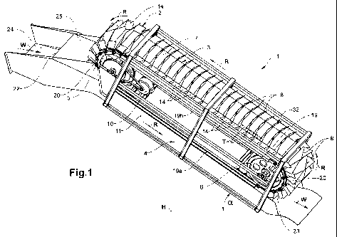
The installation 1 according to Figure 1 shows a drive arrangement 2 in the
form of a
coherent drive structure 7, which is led along a revolving direction R around
an upper deflection
element 5 and a lower deflection element 6. The drive structure 7 comprises a
load section 4, e.g. in
the form of a load line, which is positively guided along a water guidance
channel 11 (see also
Figure 9b), and a return section 3, e.g. in the form of a return line, which
is led above and parallel to
this load section.
CA 02841615 2014-01-13
The drive structure 7 is driven in the revolving direction R. The drive
structure 7 is formed
from a plurality of gravitational pressure transmission units 32 which are
present as drive links 9 (see
Figure 2a, 2b). The drive links 9 in each case comprise an onflow element 8
which along the load
section 4 engages transversely into the water guidance channel 11.
The onflow elements 8 (see Figure 2a, 2b) are designed as blade-like wall
elements and
comprise two laterally arranged wall sections 30a, 30b which are curved or
bent away out of the
plane of the onflow element 8 in a manner opposite to the movement direction R
of the drive
structure 7. The bending angle can e.g. be 10 - 300. The wall sections 30a,
30b delimit a flat, middle
wall section 30c. The onflow element 8 has a width D1 which is smaller than
the channel width by a
gap tolerance. The onflow element further has a height D3 and a depth D2.
Two adjacent onflow elements 8 together with the channel base 12c as well as
the two lateral
channel walls 12a, 12b in each case form a so-called water receiving
compartment 13, wherein the
channel base 12c and the lateral channel walls 12a, 12b are preferably
stationary. (see Figure 1, 5a,
5b, 6a, 6b and 9a - 9c). The onflow elements 8 although being led in a contact-
free manner to the
water guidance channel 11, these however form a comparatively small gap to the
channel walls 12a-
12c thanks to the exact guiding of the drive links 9, and only very little
water escapes from the water
receiving compartments 13 through this gap.
The onflow element 8 further comprises two stiffening elements 14 in the form
of transverse
walls which are arranged laterally and off-centre. The transverse walls 14
however do not represent
the lateral closure of the water receiving compartments 13, which as described
above, are terminated
laterally by the two lateral channel walls 12a, 12b.
Each drive link 9 further comprises two guide rollers 15 arranged laterally of
the onflow
element 8. The onflow element 8 moreover comprises a connection means in the
form of a fork-like
connection element 16a and of a connection body 16b lying opposite this in the
movement direction
R, and both of these are provided with suitable openings for receiving a
roller pivot 18 of the guide
rollers 15.
The drive links 9 on both sides are pushed with their respective connection
bodies 16b into
the opening between the fork lugs of the fork-like connection element 16a, for
creating the coherent
drive structure 7, wherein the roller pivot 18 is pushed through the openings
in the fork lugs as well
as in the receiver body 16b. Simultaneously, the guide roller 15 is also
fastened via the roller pivot
18 on the drive link 9 or on the drive structure 7. Hereby, it is to be noted
that the drive links 9 or the
CA 02841615 2014-01-13
16
drive structure 7 requires no pivot elements which are continuous transverse
to the movement
direction R.
The water guidance channel 11 as well as the load section 4 lie in an oblique
plane with a
constant gradient and moreover run parallel to one another. In an upper run-in
region 22 (see also
Figure 5a, 5b, 6a, 6b), the water W is led out of a feed channel 24 to the
water guidance channel 11.
The water W released from the water receiving compartments 13 leaves the
installation 1 in a lower
outlet region 23.
The run-in region 22 comprises a passage limitation element 25. The size of
the passage
opening and thus the water quantify fed to the water guidance channel 11 can
be controlled with the
passage limitation element 25, via suitable control means. However, one can
also envisage the
passage opening being fixed beforehand and not being changeable during the
operation of the
installation 1.
The installation further comprises a relief channel 27 which runs below the
water guidance
channel 11 and preferably parallel to this, as is represented in the Figures
5a, 5b and 6a, 6b. The
access to the relief channel 27 is controlled via a water guiding element 26
which can be an opening
flap or an opening slide or a bulkhead.
The water stream W can be led into the water guidance channel 11 or into the
relief channel
27 via the position of the water guiding element 26. The water guiding element
26 is likewise
activated via a control device. The discharge of the water flow W via the
relief channel 27 is effected
for example if the installation must be taken out of operation, for overhaul
and maintenance
purposes for example.
Moreover, with the occurrence of much water, a part of the water can be
discharged via the
relief channel 27. The water guiding element 26 can also generally serve for
the regulation of the
water inflow into the run-in region, in order thus e.g. to ensure a constant
revolving speed of the
drive structure.
Moreover, the water or a part thereof can also be discharged via the relief
channel 27 if
foreign matter such as e.g. solid matter is contained in the water and which
could compromise the
functioning of the installation 1. As already mentioned, it is also possible
for only a part of the water
to be discharged via the relief channel 27.
CA 02841615 2014-01-13
17
The water guiding element 26 according to the shown embodiment example is an
opening
flap in the base of the feed channel 24. In this manner e.g. heavy solid
matter can be discharged out
of the water stream W in targeted manner via the relief channel 27 whilst the
installation is in
operation. In the representations according to Figure 5a and 6a, the guiding
element 26 is set such
that the water stream is fed to the water guidance channel 11, whilst the
guiding element 26 in the
Figures 5b and 6b is set such that the water stream is fed to the relief
channel 27.
The onflow elements 8 are led via the upper deflection element 5 into the run-
in region 22,
wherein these in the run-in region 22 are brought out of a curved path at the
deflection element 5
into a linear movement path along the likewise linear water guidance channel
11 beginning in the
run-in region 22.
The load section 4 thereby lies in the linear movement path of the onflow
elements 8.
Simultaneously, the water receiving compartments 13 are also formed in the run-
in region 22. This
is effected by way of guiding the onflow elements 8 together with the water
guidance channel 11,
i.e. by way of immersing the onflow elements 8 into the water guidance channel
11.
The water flow W in the feed channel 24 is fed horizontally or with a slight
decent, to the
run-in region 22, where this is then led into the greater descent of the water
guidance channel 11.
I.e., the inclined water guidance channel 11 connects to the feed channel 24,
in the run-in region 22.
The water guidance channel 11 as well as the load section 4 has an inclination
angle a with respect
to a horizontal H.
Figures 5 and 6 now differ in the guiding of the onflow elements 8 in the run-
in region 22.
According to the embodiment variant according to Figure 5, the run-in region
22 and the guiding of
the onflow elements 8 in the run-in region 22 are designed such that in each
case only a single,
forming water receiving compartment 13 is charged with water W in the run-in
region 22. This
means that the water filling of a water receiving compartment 13 being formed
does not occur until
the associated onflow element 8 running on front has immersed into the water
guidance channel 11
up to its end position, and closes the water receiving compartment 13 running
in front.
According to the embodiment variant according to Figure 6, the run-in region
22 and the
guiding of the onflow elements 8 in the run-in region 22 are designed such
that in each case, two
water receiving compartments 13 being formed are simultaneously charged with
water W, in the
run-in region 12. In this case, the filling of a water receiving compartment
13 being formed, with
water, begins already before the associated, onflow wall 8 running in front is
immersed into its end
position into the water guidance channel 11, so that the water receiving
compartment 13 running in
CA 02841615 2014-01-13
18
=
front is not yet completely closed. I.e. the gap between the channel base 12c
and the onflow element
8 still has not reached its minimal distance.
A particular embodiment of a lower deflection element 6 is represented in each
case in the
Figures 7a and 7b. According to the embodiment according to Figure 7a, the
upper as well as the
lower deflection element 5, 6 comprise a rotation body 20 in the form of two
laterally arranged drive
wheels which are coupled via a rotation shaft and which have drive recesses 28
along their
periphery. The drive wheel 20 with the peripheral recesses or prominences,
such as e.g. teeth,
executes the function of a cog.
The power for the generation of electrical energy is taken from the upper
deflection element
5. The upper deflection element 5 for this is actively connected to an
electricity production generator
which by way of a gear device 29 takes kinetic energy from the rotation
movement of the drive
structure 7 at the drive wheel 20 and converts it into electrical energy.
In each case, a lower and an upper pair of guide profiles 19a, 19b which run
in parallel and
which form the lateral guidance of the drive links 9 in the load section 4
lying at the bottom and in
the return section 3 lying at the top, are arranged between the deflection
elements 5, 6. The guide
profiles 19a, 19b are designed as U-profiles for example, which in each case
are open to the drive
link 9. They are arranged laterally of the water guidance channel 11 above or
in the region of the
upper end section of the channel side walls 12a, 12b and are connected to a
support device or
directly or indirectly to the water guidance channel 11.
The guide rollers 15 of the drive links 9, as is shown in Figure 3 or 9,
engage on both sides
laterally into the U-shaped guide profile 19a, 19b and roll along the runner
surfaces on the guide
profile 19a, 19b. The guide rollers 15 have a rolling surface of plastic such
as POM
(polyoxymethylene). Moreover, the running surface on the guide profile 19a,
19b also consists of
plastic, such as e.g. POM. A low-noise and low-friction running behaviour of
the guide rollers 15 is
ensured in this manner.
The guide rollers are mounted in a low-friction manner via encapsulated
bearings, e.g. ball
bearings. The guide rollers 15 moreover comprise calotte-like side guidance
elements 17 which are
directed laterally outwards towards the guide profile 19a, 19b and via which
the drive links 9 are
axially guided in each case. The side guidance elements 17 as also the
corresponding guide surface
on the guide profile 19a, 19b are preferably of plastic, such as e.g. POM. The
plastic is characterised
by good sliding characteristics and its low water absorption capacity.
CA 02841615 2014-01-13
= 19
The guide rollers 15 of the drive links 9 which are led in the guide profiles
19a, 19b in each
case when running into the lower or upper deflection element 5, 6 leave the
associated guide profile
19a, 19b, wherein simultaneously the drive links 9 with their roller pivots 19
come to lie in the drive
recesses 28. The rotation body 20 is driven by the drive structure 7 by way of
this type of positive fit,
wherein the drive structure 7 is simultaneously guided in an optimal manner.
In the specific
embodiment example, the free pivot section lying laterally outside the fork-
like connection element
16a comes to lie in the drive recess 28.
The embodiment according to Figure 7b now differs from the embodiment
according to
Figure 7a described above, in that the lower deflection element 6 for the
guided deflection of the
drive structure 7 does not comprise a rotation body, but an arcuate guide
profile 19c with an arched
guide track. The arcuate guide profile 19c connects the lower guide profile
19a of the load section 4
to the upper guide profile 19b of the return section 3.
The drive links 9 of the drive structure 7 in this manner are led along the
arched guide track
from the load section 4 into the return section 3. The transition arch 91 from
the load section 4 into
the arcuate guide track of the lower deflection element 6 can be designed as a
clothoid.
Of course, the deflection elements 5, 6 can comprise rotation bodies with
recesses for
receiving the roller pivots, as well as a curved guide profile with an arched
guide track, so that the
drive structure 7 is led via the guide rollers in the guide profile as well as
via the rotation pivots in
the recesses of the drive wheel (see Figure 10).
The installation according to the invention is in particular suitable for a
modular construction
of a hydropower installation. Thus for example several installations according
to the invention and
which are described above can be arranged next to one another as is shown in
Figure 8 by way of
example and in this manner can be combined into a hydropower installation 40.
Moreover, also
several installations according to the invention alternatively or in
combination with the previously
mentioned parallel arrangement, can be arranged one after the other, i.e. in
series.
Depending on the occurrence of water, for example individual installations 1
can be
connected or disconnected. This is effected via the control of the water feed
into the individual run-
in regions.
The perspective part-view of a particular embodiment of an installation
according to the
invention and which is shown in Figure 10 comprises two guide rails 69 which
are distanced to one
another, run parallel to one another and form a closed guidance along a
revolving path. The guide
CA 02841615 2014-01-13
rails 69 in each case have an inclined and level guide section, in a load
section and return section 54,
53.
The guide rails 69 in an upper and a lower deflection region are designed as
arched
deflection elements 5, 6 which deflect the gravitational pressure transmission
units out of the return
section into the load section and vice versa. The mentioned arch pieces
connect the straight guide
sections of the guide rails in the load section and return section 54, 53 in
each case into a closed
guide track. A positive guidance results from this.
The guide rails for example comprise a U-shaped profile longitudinal body. The
U-shaped
profile longitudinal bodies of the guide rails 69 are open towards one
another. The gravitational
pressure transmission units (not shown) are now arranged between the two guide
rails 69 and are
guided via corresponding guide elements, in the guide rails 69.
In the upper deflection region, the guide rails 69 are guided with their
arched sections around
or along the periphery of a rotation body 55. The rotation body 55 comprises
two drive wheels 70
which are distanced to one another and are connected to one another via a
rotation shaft.
The drive wheels 70 comprise drive recesses which are arranged along their
periphery and
into which the gravitational pressure transmission units engage (not shown)
and in this manner drive
the rotation body 55.
The rotation body 55 is coupled to the electricity production generator 60 for
the purpose of
tapping power. The rotation body 55 and thus the electricity production
generator 60 are driven by
way of the push force and/or pull force of the gravitational pressure
transmission units.
One possible design solution of the positive guiding according to the third
sub variant
described further above is represented in Figure 11. The embodiment according
to Figure 11 shows
a rectangular water guidance channel 111 with a channel base 112c and two
channel side walls 112a,
112b. Guide rails 119 are arranged laterally on the water guidance channel 11
at both sides, in the
opening-side region of the channel side walls 112a, 112b.
The gravitational pressure transmission unit 132 with its onflow element 108
is arranged in
the water guidance channel 111. The onflow element 108 is guided in the water
guidance channel
111 in a contact-free manner, but however assumes practically the complete
cross section of the
water guidance channel 111 whilst forming small gap distances.
CA 02841615 2014-01-13
21
=
The gravitational pressure transmission unit 132 comprises two sliding
elements 115 which
with respect to the revolving direction are arranged on the radially inwardly
lying end section of the
onflow element 108 and laterally of this section.
The guide rails 119 each comprise a U-shaped longitudinal profile which is
open towards the
sliding elements 115 which are assigned to these guide rails. The longitudinal
profiles are thus
directed towards one another with their guide channel openings. The sliding
elements 115 are led in
the guide channel in a sliding manner.
The sliding elements 115 each comprise a calotte-like side guidance element
117 which is
directed laterally outwards towards the guide rail 119 and via which the
gravitational pressure
transmission unit 132 is guided laterally in the guide rail 119.
The sliding elements 115 are fastened on the onflow element 108 via connection
pivots 114
arranged transversely to the revolving direction.
One possible design solution of the positive guiding according to the second
embodiment
variant described further above is represented in Figure 12. The installation
according to Figure 12
likewise shows a rectangular water guidance channel 211 with a channel base
212c and two channel
side walls 212a, 212b.
A guide rail 219 is arranged above the water guidance channel 211. The guide
rail 219 has a
C-shaped longitudinal profile which is open towards the water guidance channel
21 and forms a gap-
like guide channel opening.
The gravitational pressure transmission unit 232 with its onflow element 208
is arranged in
the water guidance channel 211. The onflow element 208 is led in the water
guidance channel 211 in
a contact-free manner but assumes practically the complete cross section of
the water guidance
channel 211 amid the formation of small gap distances.
The gravitational pressure transmission unit 232 comprises two guide rollers
215 which are
distanced to one another, connected to one another via a pivot, and via the
onflow element 208 are
arranged between the end sections of the onflow element 208 and here outside
of the water guidance
channel 211, said end sections being lateral considered in the revolving
direction. The guide rollers
215 are guided in a rolling manner in the C-shaped guide channel of the guide
rail 219.
CA 02841615 2014-01-13
22
The guide rollers 215 are connected to the onflow element 208 via a suspension
led through
the guide channel opening. The gravitational pressure transmission unit 232
furthermore in the
region of the suspension comprises a horizontal guide element 216 which is led
in the gap-like guide
channel opening and thus laterally guides the onflow element 208. The
horizontal guide element 216
can likewise be a roller.
Three sub-variants of the first embodiment variant of the positive guiding
according to the
invention and which is described further above is represented schematically in
Figures 13 to 15. The
installation 301, 401, 501 comprises a drive arrangement 302, 402, 502 with a
plurality of
gravitational pressure transmission units 332, 432, 532 which are arranged one
after the other and
distanced to one another.
The gravitational pressure transmission units 332, 432, 532 each comprise an
onflow
element 308, 408, 508. Adjacent onflow elements 308, 408, 508 in each case in
a load section 304,
404, 504 form water receiving compartments 313, 413, 513.
The gravitational pressure transmission units 332 seen in the revolving
direction R further in
each case comprise two guide elements 315, 415, 515 which are arranged
laterally of the onflow
element 308, 408, 508.
The installation 301, 401, 501 moreover comprises two guide rails 319, 419,
519 which are
arranged parallel to one another in each case laterally of the water guidance
channel or on the water
guidance channel (not shown) and are distanced to one another. The guide rails
319, 419, 519
amongst others lead through a load section 304, 404, 504 and a return section
303, 403, 503.
The guide rails 319, 419, 519 from a closed positive guiding along the
revolving path of the
gravitational pressure transmission units 332, 432, 532. The gravitational
pressure transmission units
332, 432, 532 are positively guided along the guide rails 319, 419, 519 via
the guide elements 315,
415, 515.
Water 333, 433, 533 in a run-in region 322, 422, 522 which is located at a
higher level now
runs into the water receiving compartments 313, 413, 513 and moves the
gravitational pressure
transmission units 332, 432, 532 in the direction of a outlet region 323, 423,
523, in which the water
is discharged again out of the water receiving compartments 313, 413, 513.
The water 333, 433, 533 in the outlet region 323, 423, 523 preferably flows in
the vertical
direction or essentially in the vertical direction downwards out of the water
receiving compartments
CA 02841615 2014-01-13
23 =
313, 413, 513, so that the onflow elements 308, 408, 508 entrain as little as
possible residual water in
the direction of the return section 303, 403, 503.
The deflection element at the upper and lower deflection section amongst other
things is
designed by way of arched sections of the guide rails 319, 419, 519 which
connect the load section
to the return section of the guide rails.
The first sub-variant mentioned above is now described in Figure 13. The guide
elements
315 here with respect to the closed revolving path are arranged laterally on
the radially outer- lying
end section of the onflow element 308. The guide rails 319, in which the guide
elements 315 are
guided, are arranged laterally in the region of the end section of the water
guidance channel 311
which is towards the base.
According to this arrangement, the water receiving compartments 313 in the
deflection at the
upper and lower deflection element are reduced in a wedge-like manner due to
the radial alignment
of the onflow elements 308 in the deflection arch.
The positive guiding according to the present first sub-variant in comparison
to the second
and in particular to the third sub-variant permits an extremely compact
construction manner of the
installation, without the receiving capacity of the water receiving
compartments or the length of the
load section being reduced on account of this.
The above mentioned third sub-variant is represented in Figure 14. The guide
elements 415
here with respect to the closed revolving path are arranged at the radially
inwardly lying end section
of the onflow element 408. The guide rails 419, in which the guide elements
415 are led, can be
arranged laterally in the region of the opening-side end section of the water
guidance channel 411 or
over the water guidance channel 411 (see also Figure 11 and 12).
A cross section through the water guidance channel of one possible design
solution of the
positive guidance according to this third sub-variant is represented in Figure
11, as already
mentioned
The second sub-variant mentioned above is represented in Figure 15. The guide
elements
515 with respect to the closed revolving path are arranged laterally between
the radially outwardly
and inwardly lying end sections of the onflow element 508. The guide rails 519
are arranged in the
channel side walls, laterally in the region between the end section towards
the base and the opening-
side end section, of the water guidance channel 511.
CA 02841615 2014-01-13
24
Figure 16 shows the third sub-variant of a positive guidance (see also Figure
12 and 14)
which is described above. The installation 601 comprises a guide rail 619
which is arranged
centrally above the water guidance channel 611. The gravitational pressure
transmission units 632 in
each case comprise an onflow element 608 as well as a guide element 615 which
is arranged above
the onflow element 608 centrally between its end sections which are lateral
seen in the revolving
direction, said guide element being guided in the guide rail 619 in the region
of the load section 604.
The run-in region 622 is designed such that the water 633 amongst other things
flows
laterally obliquely into the forming water receiving compartments 613 and
flows onto the onflow
element 608 immersing into the water guidance channel 611. A quicker and more
efficient filling of
the water receiving compartments 613 is achieved by way of this
A cross section through the water guidance channel of one possible design
solution of the
positive guidance according to this second embodiment variant is represented
in Figure 12, as
already mentioned.
Figure 17 shows a part-view of the outlet region 723 of a further embodiment
of an
installation 701 according to the invention. The installation 701 comprises a
drive arrangement with
a multitude of gravitational pressure transmission units 732 which are
positively guided along a
closed revolving path 732. The positive guiding of the drive arrangement 702
is effected via guide
elements 715 led in a guide rail 719, and corresponds to the positive guidance
according to the third
sub-variant according to Figure 14. The citations with regard to Figure 14 are
referred to with regard
to the description of the positive guidance.
The gravitational pressure transmission units 732 in each case comprise an
onflow element
708 which extends transversely over the width of the water guidance channel
711. Two adjacent
onflow elements 708 in each case together with the water guidance channel 711
form a water
receiving compartment 713.
The installation 701 comprises a load section 704 which runs in an inclined
manner and is
with outlet region 723 arranged at the lower end of this load section. A shaft-
like outlet or discharge
is provided in the outlet region 723, via which the water 733 held in the
water receiving
compartments 713 is let out or discharged essentially vertically downwards.
=
CA 02841615 2014-01-13
The gravitational pressure transmission units 732 subsequently to the
discharge of the water
733, are led around in an arch into a return section 703 which leads the
gravitational pressure
transmission units 732 back again into the run-in region (not shown).
The deflection element in the lower deflection region is formed by an arched
section of the
guide rail 719 which connects the load section to the return section of the
guide rail 719.
The drive arrangement 702 in the lower region of the load section 704 is
engaged with a tow
drive. The tow drive 706 comprises a flexible drive element 727 which is led
around two deflection
elements 725, 726 distanced to one another, and this drive element is engaged
positively and/or non-
positively (frictional connection) with the drive arrangement 702 via an
engagement section.
The gravitational pressure transmission units 732 of the drive arrangement 702
which are led
past the tow drive 706 to the lower deflection element now drive the drive
element 727 of the tow
drive 706. A generator 710 draws torque at one of the deflection elements 726
of the tow drive 706,
for producing electricity.
Figure 18 shows a part-view of the outlet region 823 of a further embodiment
of an
installation 801according to the invention. The installation 801 comprises a
drive arrangement 802
with a multitude of gravitational pressure transmission units 32 positively
guided along a closed
revolving path.
The gravitational pressure transmission units 832 each comprise an onflow
element 808
extending transversely over the width of the water guidance channel 827. These
in the load section
804 divide the water guidance channel 827 into water receiving compartments.
The water guidance
channel 827 is designed closed in a tubular manner in the load section 804.
The tubular water
guidance channel 827 is open to the bottom in the outlet region 823, so that
the water can flow away
out of the water receiving compartments.
The gravitational pressure transmission units 832 are not connected to one
another in a fixed
manner but are designed as push bodies. The gravitational pressure
transmission units 832 for this
comprise force transmission elements 810, 811 for transmitting push forces
from a gravitational
pressure transmission unit 382 which runs in front in the revolving direction,
to a subsequent
gravitational pressure transmission unit 832.
The force transmission elements 810, 811 comprise push surfaces which
cooperate with one
another and via which the push forces are transferred further between the
gravitational pressure
CA 02841615 2014-01-13
26
transmission units 832. In this manner, the drive arrangement can be moved
purely via push forces
similarly to a drive chain, in the revolving direction around the deflection
elements, without however
the gravitational pressure transmission units 832 being fixedly connected to
one another.
A rotation body 826 is arranged in the lower deflection region. The rotation
body 826 at its
periphery comprises recesses, into which elements such as e.g. the onflow
elements 808 of the
gravitational pressure transmission units 832 engage. The rotation body 826 is
driven via this
positive engagement by gravitational pressure transmission units 832. The
rotation body 826 forms
part of the lower deflection element. The tubular water guidance channel,
which at the same time is
a guide rail for the drive arrangement 802, as a further part of the
deflection element is led in an
arched manner about the rotation body 826 and connects the load section to the
return section (not
shown) of the water guidance channel or of the guide rail. The tubular guide
rail in the arched
deflection section is open towards the rotation body 826, so that the elements
of the gravitational
pressure transmission units 832 can engage into the recesses on the rotation
body 826.
The rotation body 826 is connected via a drive means 806, such as belt or
gear, to a generator
830. This takes power from the drive arrangement 802 for producing
electricity.