Note : Les descriptions sont présentées dans la langue officielle dans laquelle elles ont été soumises.
CA 02841784 2014-01-14
WO 2013/010180
PCT/US2012/046958
1 SEALING MECHANISM AND METHOD FOR DROP CABLE SPLICE
ENCLOSURES
CROSS REFERENCE TO RELATED APPLICATION
[0001] This application claims priority to U.S. Patent Application
13/370,931, filed
February 10, 2012 which claims the benefit of and priority to Provisional
Application No.
61/507,988, filed July 14, 2011, which is fully incorporated herein by this
reference.
FIELD OF THE INVENTION
[0002] This invention relates to drop cable splice enclosures, and more
particularly, to a
method and mechanism for sealing communication transmission cables or drop
wires in cable
or wire splice enclosures.
[0003] A typical use of these splicing enclosures would be for fiber
to the home (FTTH)
optical fiber cables used in high speed broadband, telephone, and satellite
television
installations, or other communications cables or wires such as copper drop
wire or aerial
wire, and coaxial cables.
BACKGROUND
[0004] The following description of the invention relates to optical
fiber cable
installations and related optical fiber splicing, although certain aspects of
the invention are
applicable to other types of cable or wire splicing techniques and related
cable splice
enclosures.
[0005] One embodiment of the present invention provides a grommet
assembly used for
sealing fiber optic cables of various types in the entry holes contained in
optical fiber cable
splicing enclosures. Such enclosures are commonly placed in service in outdoor
environments and are used in the storage, management and distribution of fiber
optic cables
that enter through sealed openings in the enclosure. The enclosures serve
multiple functions
including protecting the internal fiber optic cables and cable splices from
the elements. They
can contain optical fiber splice trays or other means for making and
maintaining spliced
connections between the optical fibers.
[0006] These enclosures can contain optical fiber wire splices for
different types of
optical fiber cable, including distribution cable or feeder cable, branch
cables, and drop wire
cable. Trouble-free entry and reentry to the enclosure for these fiber optic
cables is a
necessity for long term use in making the necessary cable splices.
[0007] In current optical fiber cable splicing enclosures, cable is fed
through an entry
hole in the enclosure and through a rubber grommet. The grommet is forced down
into the
hole, forming a seal. The interior space in most enclosures is limited, and it
is difficult to
prepare the end of the cable after it has been installed in the enclosure.
-1-
CA 02841784 2014-01-14
WO 2013/010180
PCT/US2012/046958
1 [0008] The present invention provides a solution to the problem,
which includes
installing the cable in a grommet assembly, outside the enclosure, in
preparation for sealing
the cable in the grommet and sealing the grommet in an entry hole in the base
of the
enclosure.
SUMMARY
[0009] Briefly, according to one embodiment of the invention, a
compression grommet
assembly is prepared for use outside an optical fiber cable splicing
enclosure. The grommet
assembly is adapted to receive a fiber optic cable inserted into a passageway
through the
grommet assembly. The cable is initially prepared for splicing, preferably
outside the
enclosure, after the cable is inserted into the passageway through the grommet
assembly.
Cable preparation includes removing a cable sheath from the exterior of the
cable, to free up
the optical fiber wire contained in the cable. The compression grommet
assembly and the
cable are then inserted into an entry opening in the enclosure base. Once the
grommet
assembly is positioned in the entry opening, the grommet assembly is then
secured in the
opening by engaging a keyed locking mechanism that locks the grommet assembly
in the
opening. After the complete assembly is installed and locked in place, a
rubber or
elastomeric grommet material contained in the assembly can be compressed, from
a
compression force applied from outside the enclosure, to form a seal between
the grommet
and the entry opening. The grommet seals to irregular-shaped cables as well as
standard,
round-shaped cables. A seal is also formed between the grommet and the cable
passing
through the grommet. The fiber optic wire contained in the cable, which was
prepared
outside the enclosure, is then free to better facilitate fiber splicing inside
the enclosure.
[0010] The compression grommet assembly, according to one embodiment of
the
invention, includes upper and lower pressure plates on opposite sides of the
compressible
grommet. The upper pressure plate has a keyed structure that can be rotated or
otherwise
moved into engagement with a cooperating keyed portion of the entry opening,
to lock the
grommet assembly in the entry opening. An adjustment mechanism on the grommet
assembly is adapted to apply a compression force to the grommet, which then
compresses the
grommet between the pressure plates to seal the grommet in the entry opening
while at the
same time sealing the cable in the passageway through the grommet.
[0011] The cable sealing method and mechanisms according to this
embodiment of the
invention are applicable to and adapted for use with large multi-fiber
distribution cable,
branch cable, and single-fiber drop wire, as described in more detail in the
following detailed
description and the related drawings.
[0012] Other aspects of the invention also will be more fully
understood by referring to
the following detailed description and the accompanying drawings.
-2-
CA 02841784 2014-01-14
WO 2013/010180
PCT/US2012/046958
1 BRIEF DESCRIPTION OF THE DRAWINGS
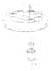
[0013] FIG. 1 is an exploded perspective view showing a six-port
compression grommet
assembly according to one embodiment of this invention.
[0014] FIG. 1A is a perspective view showing fiber drop wire inserted,
one at a time,
through holes in the compression grommet assembly.
[0015] FIG. 2 is a perspective view showing the ends of the drop wires
which have been
prepared for fiber splicing, outside an optical fiber cable splicing
enclosure.
[0016] FIG. 3 is a perspective view showing the grommet assembly of
FIG. 2 in the
process of being fed through entry openings in the base of an optical fiber
cable splicing
enclosure.
[0017] FIG. 3A is a perspective view showing the grommet assembly of
FIG. 3, but more
accurately showing the fiber optic cables that were prepared for splicing and
have been
inserted through passageways in the compression grommet assembly.
[0018] FIG. 4 is a perspective view showing the grommet assembly of
FIG. 3 inserted in
an enclosure base entry opening, along with tabs on a twist-lock mechanism
contained in the
compression grommet assembly, where the tabs have been aligned with the entry
opening in
the enclosure base.
[0019] FIG. 5 is an enlarged perspective view showing the complete
grommet assembly
that has been rotated approximately 30 degrees in a counter-clockwise
direction, to a locked
position in the enclosure entry opening, to prevent removal of the grommet
from the opening.
[0020] FIG. 5A is a perspective view similar to FIG. 5 but showing the
buffer tubes of the
fiber optic cables cut off, for clarity.
[0021] FIG. 6 is a perspective view showing a tool, such as a standard
nut driver, being
used to tighten components of the grommet assembly to compress the grommet for
forming a
seal between the fiber drop wire and the enclosure base.
[0022] FIG. 7 is a cross-sectional view, taken on line 7-7 of FIG. 8,
showing components
of the compression grommet assembly of FIGs. 1-6, in a relaxed state.
[0023] FIG. 8 is a top view of the grommet assembly shown in FIG. 7.
[0024] FIG. 9 is a cross-sectional view, taken on line 9-9 of FIG. 10,
showing
components of the compression grommet assembly of FIG. 7, in a compressed
state.
[0025] FIG. 10 is a top view of the grommet assembly shown in FIG. 9.
[0026] FIG. 11 is a bottom perspective view showing the construction of
the grommet
assembly's lower pressure plate and its means for applying the compression
force to the
grommet assembly.
[0027] FIG. 12 is an enlarged perspective view, with the drop cables
removed for clarity,
showing the grommet assembly during its insertion into the base of the
enclosure.
[0028] FIG. 13 is an enlarged perspective view showing the grommet
assembly of FIG.
11 fully inserted into the base opening.
-3-
CA 02841784 2014-01-14
WO 2013/010180
PCT/US2012/046958
1 [0029] FIG. 14 is an enlarged perspective view showing the grommet
assembly of FIG.
12, rotated from its position in FIG. 12 and showing the grommet assembly in a
locked
position.
[0030] FIG. 15 is an exploded perspective view showing components of
an alternative
form of the compression grommet assembly, which is used for a larger-diameter,
multi-fiber
cable.
[0031] FIG. 16 is a cross-sectional view, taken on line 16-16 of FIG.
17, showing
components of the compression grommet assembly of FIG. 15.
[0032] FIG. 17 is a top elevational view showing a large-diameter
fiber optic cable
passing through an opening in the alternative compression grommet assembly of
FIGs. 15
and 16.
DETAILED DESCRIPTION
[0033] Referring to the drawings, FIGs. 1-13 show one embodiment of a
compression
grommet assembly 20 according to principles of this invention. This grommet
assembly is
used for sealing drop cables of various types in the entry holes contained in
cable splicing
enclosures. Such drop cables may include, but are not limited to, optical
fiber cables,
including distribution or feeder cables, branch cables, or fiber drop wire
cables; copper drop
wires or aerial wires; coaxial cables, or other communication wire or cable
that may be
installed in an enclosure for splicing or other distribution connections. One
such enclosure is
partially shown in FIGs. 3-6 which show a base section 22 of a cable splicing
enclosure.
Referring to FIGs. 1 and 1A, the compression grommet assembly 20 includes a
compressible
grommet 24, an upper pressure plate 26 on top, and a lower pressure plate 28
on the bottom
of the grommet assembly. The pressure plates are rigid and are preferably made
of hard
plastic. The two pressure plates 26, 28 contain circumferentially spaced apart
holes 30
(shown in the upper pressure plate) and holes 42 with the same spacing (in the
lower pressure
plate). The holes 30, 42 receive optical fiber cables such as the optical
fiber drop cables 32
shown, as an example, in FIGs. 1A-6. Other types of communication cables can
be used with
the invention; the illustrated optical fiber drop cables are simply one
example.
[0034] The upper pressure plate includes radially spaced apart ribs 33
between the holes
30 for added rigidity. The lower pressure plate contains elongated, spaced
apart ribs 58
between the holes 42, also for added rigidity.
[0035] The optical fiber drop cables 32 are known in the art and
generally include an
outer insulating jacket or sheath 34 which contains an optical fiber wire 36
contained in a
buffer tube 38, and a pair of tension members 40 on opposite sides of the
optical fiber buffer
tube. One of the drop cables is shown at 32' in FIG. 1A passing through the
compression
grommet assembly. The other drop cables are shown in position for being
inserted one at a
time into corresponding holes or passageways extending through the grommet
assembly.
-4-
CA 02841784 2014-01-14
WO 2013/010180
PCT/US2012/046958
1 [0036] The internal construction of the grommet assembly, which is
adapted to receive
the drop cables, is best understood by initially referring to the cross-
sectional view of FIG. 7.
The grommet 24 is shown sandwiched between the upper pressure plate 26 and the
lower
pressure plate 28. The spaced apart holes 30 in the upper pressure plate 26
are aligned
vertically with corresponding circumferentially spaced apart holes 42 in the
lower pressure
plate 28. The separate pairs of vertically aligned holes 30 and 42 in the
pressure plates are
also aligned with corresponding open-ended passages 44 extending through the
depth of the
grommet 24. The vertically aligned holes 30, 44 and 42 form separate
passageways
extending through the lower pressure plate, the grommet, and the upper
pressure plate, for
receiving corresponding ones of the drop cables 32. The holes of the
passageways are
preferably shaped to match the outer configuration of the drop cable, which is
generally oval
in shape as shown in FIG. 1, for example. The grommet assembly of this
invention is
adapted to seal around various irregular-shaped cables, as well as standard
shapes such as
round cables. The illustrated embodiment is optimized to seal to oval-shaped
cables.
[0037] The procedure for inserting the drop cables into the base of the
enclosure first
involves inserting the cables, one at a time, through corresponding
passageways in the
grommet assembly 20. As illustrated in FIG. 1A, the cable 32' has been
inserted through a
corresponding passageway in the grommet assembly from a position outside of
the enclosure
base. Once the drop cables have been inserted through the passageways in the
compression
grommet assembly, the free ends of the cables are then prepared for subsequent
cable
splicing. The ends of the cables can be, and preferably are, prepared for
splicing outside the
enclosure. The ends of the drop cables are prepared by removing or stripping
away the
portion of the sheath 34 on the each cable which extends away from a location
a short
distance above the upper pressure plate 26. Removing the sheath from each
cable frees up
the optical fiber wires 36' for use in subsequent splicing, after the grommet
assembly (and the
prepared cables) have been inserted as a unit into the enclosure base, as
described below.
[0038] FIG. 2 shows a group of the drop cables 32 after they have been
inserted through
their respective passageways in the grommet assembly, from a position exterior
to the
enclosure. The prepared ends of the cables are shown with the cables in their
entirety having
been inserted entirely through the upper pressure plate 26 of the grommet
assembly. The
prepared ends of the cables (the fiber optic wires 36', the buffer tubes 38,
and the tension
members 40) are exposed individually above the upper pressure plate 26.
[0039] FIG. 3 shows the next step in the process in which the prepared
drop cables 32
(and the grommet assembly 20) are inserted through entry holes 44 in the base
22 of the
enclosure, from a position outside the enclosure. As illustrated in FIG. 3,
the grommet
assembly is inserted through the bottom of the base opening (entry hole 44) in
the upward
direction as shown by the arrow 46. (The unsupported wires 36' are shown out
of proportion
as to their length from the free end of the cables, for clarity.)
-5-
CA 02841784 2014-01-14
WO 2013/010180
PCT/US2012/046958
1 [0040] FIG. 3A is similar to FIG. 3, but more accurately shows the
fiber optic cables 32
that were prepared for splicing and have been inserted through the passageways
in the
compression grommet assembly. This view shows the sheath 34 having been
removed, the
ends of the tension members 40 shortened, and the buffer tubes 38 used for
guiding and
supporting the wires 36 as the grommet assembly is being inserted into the
passage 44
through the base section 22.
[0041] FIG. 4 shows the compression grommet assembly during its initial
insertion into
the opening 44 in the enclosure base, loosely fitted into its initial position
in the entry hole
44. Locking tabs 62 on the upper pressure plate (described in more detail
below) are aligned
with a keyed upper portion of the opening 44 in the enclosure base (described
below). The
wires 36' are shown unsupported by the buffer tubes which are cut off in FIG.
4, for clarity.
[0042] FIG. 5 shows the compression grommet assembly having been fully
inserted into
the base opening 44 and then rotated in a counter-clockwise direction (to a
locked position)
as shown by the arrows in FIG. 5. FIG. 5A shows a similar view, but with the
buffer tubes
cut off, for clarity. In the illustrated embodiment, the grommet assembly is
twist-locked
(rotated) through an angle of about 30 from its initial unlocked position in
the opening (FIG.
4) to the locked position in FIG. 5. (Construction of the twist-lock mechanism
is described in
more detail below.) In its locked position the grommet assembly is prevented
from being
dislodged from its base opening 44 while in its unsealed position in the
opening 44. The
grommet assembly is preferably rotated to the locked position manually from
below the base
plate 22. The assembly can be rotated on its axis, using the stiffness of the
cables extending
downwardly away from the bottom of the base plate to apply the necessary
leverage.
[0043] FIG. 6 shows the next step in the process in which the grommet
assembly is
compression-sealed in the base opening 44, using a tool to apply a compression
force from a
position outside of the enclosure. This view illustrates use of the tool, such
as a standard nut
driver 48, being used to tighten pressure-applying components of the grommet
assembly, to
compress the rubber or elastomeric grommet material in the opening, for
sealing the grommet
in the opening. Applying compression to the grommet also at the same time
seals the drop
cables in their respective passageways through the grommet assembly.
[0044] FIGs. 7-10 best illustrate components of the compression grommet
assembly
useful in sealing the grommet in the base opening while also sealing the
grommet to the drop
cables passing through it. FIG. 7 shows elements of the grommet assembly in a
"relaxed"
position in the base opening, i.e., prior to applying the compression force.
The dimension X
shown in FIG. 7 illustrates the vertical dimension of the grommet assembly in
its relaxed
state. The cross-sectional view shows the drop cable 32 extending through one
of the
passageways formed by the opening 42 in the lower pressure plate 28, the
passage 44 through
the grommet 24, and the opening 30 in the upper pressure plate 26. The grommet
assembly
also includes an adjustable connector assembly which includes an elongated
bolt 50
-6-
CA 02841784 2014-01-14
WO 2013/010180
PCT/US2012/046958
1 extending vertically through a central passageway in the grommet
assembly. The bolt has its
head 51 engaging a washer 52 at the base of the lower pressure plate. The bolt
is preferably
made of stainless steel. The central passageway is foiiiied by vertically
aligned openings 53,
54 and 56 in the lower pressure plate, the grommet, and the upper pressure
plate,
respectively.
[0045] The bolt 50 is held in a fixed position in the central
passageway by having
threaded it into an internally threaded tubular insert 57 affixed to the upper
pressure plate in
alignment with the central passageway through the grommet. The insert is
preferably made
of brass and molded into the upper pressure plate. The head 51 on the bolt is
positioned
below the lower pressure plate and can be tightened to apply the compressive
force to the
grommet. Tightening of the bolt against the bottom of the lower pressure plate
causes the
upper and lower pressure plates to squeeze against the grommet 24 to apply a
compressive
force to the grommet. The force acts against the walls of the opening 44 in
the base, as
shown in FIG. 9, which illustrates the grommet assembly in its compressed
state. The
dimension Y in FIG. 9 illustrates the depthwise shortening of the grommet in
the opening 44
caused by compressing the grommet against the wall of the opening to apply the
pressure
sufficient to form the seal.
[0046] FIG. 11 is a bottom perspective view of the compression grommet
assembly
which shows more detailed construction of the lower pressure plate 28. The
spaced apart
bottom holes 42 in the lower pressure plate are positioned between radially
extending ribs 58
that converge toward the center bottom of the lower pressure plate. The ribs
58 distribute the
force of the bolt evenly over the lower pressure plate. The enlarged length of
the ribs allows
easier access for tightening the bolt.
[0047] The grommet 24 is preferably made from a rubber or elastomeric
material. One
useful grommet material is an injection moldable theinioplastic elastomer, and
another is
made from silicone rubber, or a urethane rubber. Certain blended elastomeric
materials made
from Kraton styrenic block copolymers may be useful to produce the desired
compressibility
properties. The material should be of a relatively low hardness, preferably
haying a Shore A
hardness from about 10 to 40, and more preferably from about 20 to 30. Such
materials are
useful in sealing around irregular-shaped cables, in addition to standard
shapes.
[0048] The twist-lock function of the invention is best understood by
referring to the
detailed construction of the upper pressure plate 26. This is best illustrated
in FIGs. 1 and
1A, and in FIGs. 12-14 which show the upper pressure plate unobstructed by the
cables 32,
for clarity. The upper pressure plate 26 of each grommet assembly includes a
profiled outer
edge that is keyed to a cooperating profiled interior surface near the top of
the each
corresponding entry hole 44 in the enclosure base.
[0049] A plurality of outwardly projecting narrow profile tabs 62 are
circumferentially
spaced apart around the outer edge of the upper pressure plate. In the
illustrated embodiment,
-7-
CA 02841784 2014-01-14
WO 2013/010180
PCT/US2012/046958
1 there are three of these tabs equally spaced apart around the edge of the
upper pressure plate.
Each of these tabs is positioned at the top of the upper pressure plate, and
each tab is
positioned adjacent an adjoining recessed shoulder 64 on the upper pressure
plate. Each
shoulder has a width about the same as a width of the adjacent tab.
[0050] FIG. 12 best illustrates the keyed opening on the interior surface
of the entry hole
44. The keyed portion of the entry hole preferably comprises three
circumferentially spaced
apart circularly curved slotted areas 66, projecting out from a top portion of
the entry hole. A
separate narrow ridge 68 extends below the top of each slotted area 66. Each
ridge 68 has a
flat upper surface spaced below the top of the slotted area into which it
protrudes. Each ridge
has a width of about half the length of its adjacent slotted area. The
combined width of each
tab 62 on the upper pressure plate and the ridge 68 in a corresponding entry
hole is slightly
less than the total length of each corresponding slotted area 66.
[0051] FIGs. 12-14 best illustrate the twist-lock process. FIG. 12
shows the grommet
assembly during insertion into the entry hole of the base. The locking tabs 62
are first
aligned with the keyed opening in the base, and the grommet assembly is then
pushed
upwardly through the entry hole to the position shown in FIG. 12, below the
profiled upper
portion of the keyed entry hole.
[0052] FIG. 13 shows the grommet assembly fully inserted into the entry
hole, but not
rotated into its locked position. In the position shown in FIG. 13, the tabs
62 are engaged in
the slotted areas 66 and positioned adjacent the ridges 68 on the keyed
opening.
[0053] FIG. 14 shows a grommet assembly having been rotated about 30
degrees
counter-clockwise into its locked position. Here, the tabs 62 are rotated over
the ridges 68 so
that the interference between the two keyed portions can prevent the grommet
assembly from
being dislodged from the entry hole. In the view shown in FIG. 14, the
trailing shoulders 64
on the upper pressure plate are shown adjacent the trailing edge of each tab
62.
[0054] In the position shown in FIG. 14, the grommet assembly is still
in its relaxed or
unsealed position in the entry hole, and once the connector assembly
(described previously)
has been tightened to apply the compression force, the grommet assembly cannot
be rotated
to the unlocked position.
[0055] The cables entering the enclosure through their corresponding
grommet
assemblies can be spliced to other communication lines within the fiber
distribution enclosure
in the usual manner. The sealed holes can provide passageway for fiber optic
cables of
various types, including main distribution cable or feeder cable, branch
cables and/or drop
wire cables, or other communication cables as mentioned previously. The
interior of the
distribution enclosure can include an upright support bar and other support
structures (not
shown) for holding fiber splice trays (not shown) or means for making splice
connections or
modifications in the interior of the enclosure. Such fiber splice connections
are illustrated,
-8-
CA 02841784 2014-01-14
WO 2013/010180
PCT/US2012/046958
1 for example, in applicant's published US Patent Application No.
2011/0262094, which is
incorporated herein, in its entirety, by this reference.
[0056] FIG. 15 illustrates an alternate form of the invention in which
a grommet
assembly 70 is adapted for sealing a large-diameter multi-fiber cable 72 in
the entry hole of a
fiber splice enclosure. In this embodiment, the cable core comprises a bundle
of separate
glass fiber wires contained in corresponding buffer tubes 74. The individual
glass fiber wires
(and their buffer tubes) are contained in an outer sheath 76 and several other
protective layers
of sheathing that form a relatively rigid multi-fiber cable.
[0057] FIG. 15 also illustrates one example of the cable having been
prepared prior to
subsequent cable splicing. In this example, the sheathing at the end of the
cable has been
stripped away and one of the buffer tubes and its glass fiber wire are
exposed. They extend
loosely away from the rest of the cable for subsequent splicing to
transmitting and receiving
equipment inside the enclosure.
[0058] Referring to the exploded assembly view of FIG. 15 and the cross-
sectional view
of FIG. 16, the grommet assembly 70 includes a tubular bottom cap 78, a
plastic spacer 80
contained in the lower portion of the bottom cap, and a tubular inner grommet
82 above the
spacer. The inner grommet is contained in an upper portion of the bottom cap,
in alignment
with the lower spacer. The inner grommet can be made from substantially the
same
compressible grommet materials described previously. The spacer 80 and the
inner grommet
82 are both of narrow profile and both are in contact with the outer surface
of the cable, along
the inside of the bottom cap, when the cable extends through the grommet
assembly during
use.
[0059] An internally threaded lower section 84 of the bottom cap 82 is
radially spaced
from the adjacent tubular spacer 80. This leaves a narrow annular space within
the bottom
cap for receiving an externally threaded annular lower portion 86 of a tubular
fixed housing
88 which is threaded into the inner portion 84 of the bottom cap during use.
[0060] A tubular outer grommet 90 is seated on an annular top edge of
the bottom cap, to
position the outer grommet spaced radially outwardly from the inner grommet.
Both
grommets are aligned on a common central axis through the assembly. The inner
and outer
grommets are spaced apart on opposite sides of the downwardly facing non-
threaded tubular
portion of the housing 88. The inside diameter of the outer grommet 90
contacts the tubular
outer surface of the housing, and the outside diameter of the inner grommet 82
contacts the
inner surface of the housing.
[0061] An outer washer 92 rests on the annular top edge of the outer
grommet, making
pressure contact with a flanged upper portion 94 of the housing. Another outer
washer 96
makes pressure contact between the top edge of the bottom cap 78 and the
annular lower edge
of the outer grommet 90. An inner washer 98 makes pressure contact between the
top edge
-9-
CA 02841784 2014-01-14
WO 2013/010180
PCT/US2012/046958
1 of the inner grommet 82 and an annular inner shoulder inside the flanged
upper portion 94 of
the housing.
[0062] The flanged upper portion 94 of the upper housing 88 is
constructed similar to the
upper pressure plate 26, to provide a means for twist-locking the grommet
assembly 70 in the
entry hole of the enclosure, during use.
[0063] The components of the grommet assembly, when assembled for use
as shown in
FIG. 16, cooperate to faun a central passageway 100 along the central axis of
the assembly.
[0064] In use, the multi-fiber cable 72 is inserted through the central
opening 100 in the
grommet assembly, from outside the cable splice enclosure. The end of the
cable then can be
prepared for splicing, as shown in FIG. 16, from outside the cable splice
enclosure.
[0065] The cable 72, after having been inserted through the grommet
assembly, as shown
in FIG. 16, is then inserted into the entry hole in the base of the enclosure,
as described
previously. The assembly is initially inserted into the base opening with
locking tabs 102 on
the upper portion 94 of the housing aligned with a keyed upper portion of the
opening,
similar to the keyed portion 66-68 of the opening 44, described previously.
[0066] After the top section of the grommet assembly is fully inserted
into the base
opening, the assembly can be rotated on its axis, away from its unlocked
position to a locked
position. The assembly is twist-locked into its locked (but unsealed) position
by rotating the
bottom cap from a position outside the enclosure. The outer edge of the upper
portion 94 of
the housing 88 is profiled similar to the upper pressure plate 26, which is
keyed to a similarly
profiled keyed upper section of the base opening. Each of the tab 102 includes
an adjacent
recessed shoulder 104. The keyed inner portion of the base opening includes
curved slotted
areas and a separate narrow ridge below each slotted area, as described
previously. The
bottom cap includes vertically extending spaced apart ribs 106 to facilitate
manually rotating
the grommet assembly on its axis.
[0067] After the grommet assembly is rotated to its locked position,
the assembly is
sealed in the opening, from a compressive force applied from outside the
enclosure. The
bottom cap 78 rotates on its axis causing the threaded inside section 84 to
move upward
against the resistance of the fixed upper housing 88 which has been locked in
the opening.
This compresses both grommets 82 and 90, causing them to seal against the
cable and at the
same time to seal against the inside of the opening.
-10-