Sélection de la langue

Search

Sommaire du brevet 2843940 

Énoncé de désistement de responsabilité concernant l'information provenant de tiers

Une partie des informations de ce site Web a été fournie par des sources externes. Le gouvernement du Canada n'assume aucune responsabilité concernant la précision, l'actualité ou la fiabilité des informations fournies par les sources externes. Les utilisateurs qui désirent employer cette information devraient consulter directement la source des informations. Le contenu fourni par les sources externes n'est pas assujetti aux exigences sur les langues officielles, la protection des renseignements personnels et l'accessibilité.

Disponibilité de l'Abrégé et des Revendications

L'apparition de différences dans le texte et l'image des Revendications et de l'Abrégé dépend du moment auquel le document est publié. Les textes des Revendications et de l'Abrégé sont affichés :

  • lorsque la demande peut être examinée par le public;
  • lorsque le brevet est émis (délivrance).
(12) Brevet: (11) CA 2843940
(54) Titre français: POCHE REGLABLE POUR CHARGEUR DE MUNITIONS
(54) Titre anglais: ADJUSTABLE AMMUNITION MAGAZINE POUCH
Statut: Accordé et délivré
Données bibliographiques
(51) Classification internationale des brevets (CIB):
  • F42B 39/02 (2006.01)
  • A45C 1/00 (2006.01)
  • A45C 11/00 (2006.01)
  • A45F 5/00 (2006.01)
(72) Inventeurs :
  • BECK, JASON (Etats-Unis d'Amérique)
(73) Titulaires :
  • TYR TACTICAL, LLC
(71) Demandeurs :
  • TYR TACTICAL, LLC (Etats-Unis d'Amérique)
(74) Agent: GOWLING WLG (CANADA) LLP
(74) Co-agent:
(45) Délivré: 2018-04-17
(22) Date de dépôt: 2014-02-24
(41) Mise à la disponibilité du public: 2014-09-14
Requête d'examen: 2014-03-21
Licence disponible: S.O.
Cédé au domaine public: S.O.
(25) Langue des documents déposés: Anglais

Traité de coopération en matière de brevets (PCT): Non

(30) Données de priorité de la demande:
Numéro de la demande Pays / territoire Date
13/829,894 (Etats-Unis d'Amérique) 2013-03-14

Abrégés

Abrégé français

Description dune poche réglable ayant une partie avant, une partie arrière, une première partie latérale et une deuxième partie latérale qui sont reliées à une partie inférieure et définissent collectivement un espace intérieur qui peut être configuré pour recevoir des chargeurs de munitions de différentes tailles. Les parties avant et arrière comprennent une pluralité de bandes qui sétendent longitudinalement et les première et deuxième parties comprennent une pluralité de canaux. La pluralité de bandes et la pluralité de canaux sont configurés pour recevoir un élément élastique ayant des extrémités libres qui sont attachées ensemble. En fonctionnement, une personne peut tirer sur les extrémités libres attachées afin dajuster le volume de lespace intérieur pour accueillir des chargeurs de munitions de différentes tailles.


Abrégé anglais

An adjustable pouch having a front portion, rear portion, first side portion, and a second side portion that are connected to a bottom portion and collectively defines an interior space that may be configured to receive different sizes of ammunition magazines is disclosed. The front and rear portions include a plurality of straps that extend lengthwise and the first and second side portions include a plurality of channels. The plurality of straps and the plurality of channels are configured to receive an elastic member having free ends that are tied together. In operation, an individual can pull on the tied free ends of the elastic member in order to adjust the volume of the interior space to accommodate ammunition magazines of different sizes.

Revendications

Note : Les revendications sont présentées dans la langue officielle dans laquelle elles ont été soumises.


CLAIMS
What is claimed is:
1. An adjustable pouch comprising:
a pouch body comprising:
a front portion, a rear portion, a first side portion, and a second side
portion that are flexibly
connected to a bottom portion such that the front portion, the rear portion,
the first side portion, and
the second side portion are bent upward to define an interior space;
one or more first straps attached to the front portion of the pouch body;
one or more second straps attached to the rear portion of the pouch body; and
a first elongated elastic member received through corresponding channels
defined by the one
or more first and second straps and the first and second side portions and
binding the front portion,
the rear portion, the first side portion, and the second side portion such
that the first elongated elastic
member is adjustable to substantially even tightening of the pouch body and
modify a volume of the
interior space of the pouch body.
2. The adjustable pouch of claim 1, wherein the one or more first straps
and the one or more
second straps are attached lengthwise relative to the front portion and rear
portion, respectively.
3. The adjustable pouch of claim 1, wherein the first elongated elastic
member defines a first free
end and a second free end that are secured together through a fastener.
4. The adjustable pouch of claim 1, further comprising:
a tab portion attached to the bottom portion of the pouch body, wherein the
tab portion defines
an opening configured to receive the first elongated elastic member.
5. The adjustable pouch of claim 4, wherein the tab portion includes a ring
that defines the
opening.
6. The adjustable pouch of claim 1, further comprising:
a tab member extending from either the front portion or rear portion and
forming a tab channel;
a second elongated elastic member having one portion looped through the tab
channel of the
tab member; and
a retention member defining a retention channel configured to receive another
portion of the
second elongated elastic member, wherein the second elongated elastic member
defines a first free
8

end and a second free end that are tied together, wherein the retention member
applies a bias to an
article that is received within the interior space when the retention member
is engaged to the article.
7. The adjustable pouch of claim 6, wherein the second elongated elastic
member comprises a
rope, a chord, a string, or other type of elongated stretchable member.
8. The adjustable pouch of claim 1, wherein the corresponding channels
include a first plurality of
channels defined by the first side portion and a second plurality of channels
defined by the second
side portion.
9. The adjustable pouch of claim 1, wherein the one or more first straps
includes a sewn portion
that divides the one or more first straps into a pair of respective strap
portions.
10. The adjustable pouch of claim 1, wherein the first elongated elastic
member includes a first
free end and a second free end that are tied together and configured to be
manipulated for cinching
the first elongated elastic member relative to the pouch body to change the
volume of the interior
space.
11. The adjustable pouch of claim 1, wherein the interior space
communicates with an opening
collectively defined by the front portion, rear portion, first side portion,
and second side portion.
12. The adjustable pouch of claim 1, wherein the first elongated elastic
member includes a rope, a
chord, a string, or other type of elongated stretchable member.
13. The adjustable pouch of claim 1, wherein the front portion, rear
portion, first side portion, and
second side portion are bendable at the respective junction with the bottom
portion.
14. A method of manufacturing an adjustable pouch comprising:
forming a pouch body comprising: a front portion, a rear portion, a first side
portion, a second
side portion that are flexibly connected to a bottom portion, the first side
portion having a first channel
and the second side portion having a second channel;
attaching one or more first straps to the front portion, the one or more first
straps defining a
third channel;
attaching one or more second straps to the rear portion, the one or more
second straps
defining a fourth channel;
folding the front portion and the rear portion toward the other, while folding
the first side portion
and the second side portion toward the other to collectively define an
interior space; and
9

inserting an elongated elastic member through the first, second, third, and
fourth channels, the
elongated elastic member binding the front portion, the rear portion, the
first side portion, and the
second side portion such that the elongated elastic member is adjustable to
substantially even
tightening of the pouch body and modify a volume of the interior space of the
pouch body.
15. The method of claim 14, further comprising:
engaging the first free end and the second free end of the elongated elastic
member to a
fastener.
16. The method of claim 15, wherein the fastener includes having a spring-
biased body defining a
first aperture disposed within a fastener body defining a second aperture,
wherein alignment of the
first aperture with the second aperture allows the elongated elastic member to
pass through the
fastener.
17. The method of claim 16, wherein manipulating the fastener cinches the
elongated elastic
member relative to the pouch body for causing an even tightening around the
pouch body to adjust the
volume of the interior space.
18. The method of claim 14, further comprising:
sewing a sewn portion along each of the one or more first and second straps
such that each of
the one or more straps first and second defines a pair of respective strap
portions.
19. The method of claim 14, further comprising:
attaching a tab portion defining a channel to either to the front portion or
rear portion of the
pouch body;
securing one portion of a second elongated elastic member to the channel of
the tab portion;
and
securing another portion of the second elongated elastic member to a retention
member
configured to engage an article disposed within the interior space defined by
the pouch body.
20. An adjustable pouch comprising:
a pouch body including a front portion, a rear portion, a first side portion,
and a second side
portion that are each bendable along a corresponding connection point with a
bottom potion such that
the front portion, the rear portion, the first side portion, and the second
side portion are bent upward to
define an interior space;
a plurality of first side channels defined by the first side portion;

a plurality of second side channels defined by the second side portion; and
a first elongated member received through the plurality of first side channels
and the plurality
of second side channels thereby connecting the front portion, the rear
portion, the first side portion,
and the second side portion, such that the first elongated member is
adjustable to tighten the pouch
body and modify a volume of the interior space of the pouch body by
dynamically adjusting a distance
between each of the respective edges
21. The adjustable pouch of claim 20, further including
one or more first straps attached to the front portion of the pouch body to
define at least one
front portion channel, and
one or more second straps attached to the rear portion of the pouch body to
define at least one
rear portion channel.
22 The adjustable pouch of claim 21, wherein the first elongated member is
further received
through the at least one front portion channel.
23 The adjustable pouch of claim 21, wherein the first elongated member is
further configured to
be received through the at least one rear portion channel
24 The adjustable pouch of claim 21, wherein the one or more first straps
and the one or more
second straps are attached lengthwise relative to the front portion and rear
portion, respectively
25 The adjustable pouch of claim 21, further including a second elongated
member disposed over
the pouch body
26. The adjustable pouch of claim 25, wherein the first elongated member or
the second elongated
member includes a tied portion defined over the pouch body
27. The adjustable pouch of claim 25, wherein an article is receivable
within the interior space of
the pouch body, such that a portion of the first elongated member or the
second elongated member is
disposed around a peripheral region of the article.
11

Description

Note : Les descriptions sont présentées dans la langue officielle dans laquelle elles ont été soumises.


CA 02843940 2016-11-03
ADJUSTABLE AMMUNITION MAGAZINE POUCH
FIELD
[0001] The present document relates to an adjustable pouch for receiving
an
article, and in particular to an adjustable pouch configured to store
different types of
ammunition magazines.
BACKGROUND
[0002] Pouches are used for storing various articles. In tactical
applications,
pouches may be configured to store ammunition magazines for different types of
weapons. Since ammunition magazines have different shapes and sizes, it is a
necessary
requirement that the pouch have the capability to accommodate different kinds
of
ammunition magazines. As such, it is desirable for improvements in pouches
that are
adjustable to accommodate ammunition magazines of different sizes.
SUMMARY
[0003] In one embodiment, an adjustable pouch may include a pouch body
having a front portion, a rear portion, a first side portion, and a second
side portion that are
connected to a bottom portion that collectively define an interior space. A
first plurality of
channels is defined by the first side portion and a second plurality of
channels is defined by
the second side portion. In addition, a first plurality of straps is attached
to the front portion of
the pouch body and a second plurality of straps is attached to the rear
portion of the pouch
body. An elastic member is configured to be received through the first and
second plurality
of channels and the first and second plurality of straps such that the elastic
member binds
the pouch body together and is adjustable to modify the shape of the interior
space of the
pouch body.
[0004] In another embodiment, a method of manufacturing an adjustable
pouch
may include:
forming a pouch body comprising:
a front portion, a rear portion, a first side portion, a second side
portion that are connected to a bottom portion and
collectively define an interior space;
a first plurality of channels defined by the first side portion; and
1

CA 02843940 2016-11-03
a second plurality of channels defined by the second side
portion;
attaching one or more straps to the front portion;
attaching one or more straps to the rear portion;
folding the front portion and the rear portion toward the other, while folding
the
first side portion and the second side portion toward the other to
collectively define an interior space; and
inserting an elongated elastic member through the first plurality of channels
of
the first side portion, the second plurality of channels of the second side
portion, the one or more straps of the front portion, and the one or more
straps of the rear portion, wherein the elongated elastic member defines
an elongated body with a first free end and a second free end, wherein
the elongated elastic member.
[0005] Additional objectives, advantages and novel features will be set
forth in the description which follows or will become apparent to those
skilled in the art upon
examination of the drawings and detailed description which follows.
BRIEF DESCRIPTION OF THE DRAWINGS
[0006] FIG. 1 is an elevated perspective view of an adjustable pouch for
engagement to an ammunition magazine;
[0007] FIG. 2 is an elevated perspective view of the adjustable pouch;
[0008] FIG. 3 is a front view of the adjustable pouch;
[0009] FIG. 4 is a rear view of the adjustable pouch;
[0010] FIG. 6 is a side view of the adjustable pouch;
[0011] FIG. 6 is an opposing side view of the adjustable pouch;
[0012] FIG. 7 is a top view of the adjustable pouch;
[0013] FIG. 8 is a bottom view of the adjustable pouch;
[0014] FIG. 9 is a top plan view of an interior surface of the
adjustable
pouch in a disassembled state; and
[0015] FIG. 10 is a top plan view of an exterior surface of the
adjustable
pouch in a disassembled state.
2

CA 02843940 2016-11-03
[0016] Corresponding reference characters indicate corresponding elements
among the view of the drawings. The headings used in the figures do not limit
the
scope of the claims.
DESCRIPTION
[0017] An adjustable pouch having a pouch body configured to receive
different
types of articles, such as an ammunition magazine, using an elongated elastic
member
that binds together different portions of the pouch body such that an interior
space
defined by the adjustable pouch can be adjusted to accommodate ammunition
magazines
of different shapes and sizes is described herein. Referring to the drawings,
various
embodiments of an adjustable pouch are illustrated and generally indicated as
100 in
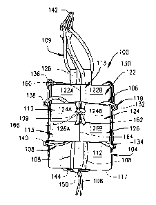
FIGS. 1-10. As illustrated in FIG. 1, the adjustable pouch 100 includes a
pouch body 104
configured to receive various types of articles, such as an ammunition
magazine 102, in
which one portion of the ammunition magazine 102 is received within an
interior space
106 (FIG. 7) defined by the pouch body 104, while the remainder of the
ammunition
magazine 102 extends outwardly from the interior space 106 through an opening
121
(FIG. 7) of the pouch body 104. As further shown, the pouch body 104 includes
a front
portion 110, a rear portion 112, a first side portion 114, a second side
portion 116 that
collectively extend from a bottom portion 117 to define the interior space 106
when bound
together using a first elongated elastic member 108. In some embodiments, the
first
elongated elastic member 108 may define an elongated body with a first free
end and a
second free end. In addition, the first elongated elastic member 108 may be a
chord, a
rope, a string or other type of elongated stretchable member made of a
material that
exhibits elastic or stretching qualities that allow the first elongated
elastic member 108 to
be stretched, tied together and/or be configured to apply a bias that binds
the front portion
110, rear portion 112, first side portion 114, and second side portion 116
together to
accommodate different sizes of ammunition magazines or the like to be engaged
to the
adjustable pouch 100.
[0018] Referring to FIG. 8, a tab portion 144 may be sewn or otherwise
secured
along the bottom portion 117 of the pouch body 104 for securing both free ends
of the first
elongated elastic member 108. The tab portion 144 includes a ring 146 that
defines and
reinforces an opening 148 configured to receive the first elongated elastic
member 108. In
some embodiments, the free ends of the first elongated elastic member 108
extend
through the fastener 150 and are tied together in a knot to secure the first
elongated
elastic member 108 to the fastener 150. In one embodiment, the fastener 150
may be
a conventional fastener that includes a spring-biased portion disposed within
a
chamber defined by the fastener 150. The fastener 150 defines a first aperture
and the
3

CA 02843940 2016-11-03
spring-biased portion defines a second aperture that may be positioned to
establish
communication with the first aperture when the first and second apertures are
substantially aligned to permit the first elongated elastic member 108 to be
inserted
through both the first and second apertures, thereby securing the first
elongated elastic
member 108 to the fastener 160.
[0019] Referring to FIGS. 1 and 2, in some embodiments the adjustable
pouch
100 may include a retainer member 142 attached to a second elongated elastic
member
109 having one portion looped through a channel defined by a tab member 128,
which is
secured to the front portion 110 of the pouch body 104 and another portion of
the second
elongated elastic member 109, which is tied to one of a plurality of straps
113 secured to
the rear portion 112 of the pouch body 104. As shown in FIG. 1, the retainer
member 142
engages and retains a portion of the ammunition magazine 102 within the
confines of the
interior space 106 of the pouch body 104.
[0020] As shown in FIGS. 1-4, in some embodiments a first plurality of
straps
113 may be a first strap 118 and a second strap 120 that extend lengthwise
across the front
portion 110 and may be sewn or otherwise secured to the front portion 110,
while in some
embodiments a second plurality of straps 113 (FIG. 4) may be a third strap
122, a fourth
strap 124, and a fifth strap 126 that are sewn or otherwise secured to the
rear portion 112 of
the pouch body 104. In other embodiments, the front portion 110 and rear
portion 112 of the
pouch body 104 may have any number of a plurality of straps 113 that allow the
first
elongated elastic member 108 to be engaged to one or more straps 113.
[0021] Referring to FIG. 3, in some embodiments the first strap 118 may
have a
sewn portion 156 that divides the first strap 118 into a strap portion 118A
and a strap
portion 118B of substantially equal length, while the second strap 120 may
have a sewn
portion 158 that divides the second strap 120 into a strap portion 120A and a
strap portion
120B of substantially equal length. Similarly, in some embodiments, the third
strap 122
may have a sewn portion 160 that divides the third strap 122 into a strap
portion 122A and a
strap portion 122B of substantially equal length, while the fourth strap 124
may have a sewn
portion 162 that divides the fourth strap 124 into a strap portion 124A and a
strap portion
124B of substantially equal length. In addition, the fifth strap 126 may have
a sewn portion
164 that divides the fifth strap 126 into a strap portion 126A and a strap
portion 126B of
substantially equal length. As shown, each of the strap portions 118A, 118B,
120A, 120B,
122A, 122B, 124A, 124B, 126A and 126B forms an open ended channel configured
to
receive a portion of the first elongated elastic member 108 when binding the
pouch body 104
together as shall be discussed in greater detail below.
4

CA 02843940 2016-11-03
[0022] Referring to FIGS. 1-6, the pouch body 114 further includes a
plurality of
channels 119 that are defined along the first side portion 114 and the second
side portion
116. The plurality of channels 119 are configured to receive respective
portions of the first
elongated elastic member 108 when binding the first and second side portions
114 and
116 to the front portion 110 and rear portion 112, respectively. As shown in
FIG. 5, in
some embodiments the first side portion 114 may define a first channel 130, a
second
channel 132, and a third channel 134 configured to receive a portion of the
first elongated
elastic member 108. Similarly, as shown in FIG. 6, in some embodiments the
second side
portion 116 may define a fourth channel 136, a fifth channel 138, and a sixth
channel 140
that are also configured to receive a portion of the first elongated elastic
member 108
when binding the pouch body 104 together.
[0023] The plurality of channels 119 formed along each the first and
second side
portions 114 and 116, respectively, establish contact points between the first
elongated
member 108 and the first and second side portions 114 and 116 such that the
front portion
110, rear portion 112, first side portion 114, and second side portion 116 of
the pouch body
104 are bound together with greater binding force by the first elongated
member 108. In
this arrangement, the plurality of channels 119 prevent the first elongated
elastic member
108 from slipping or otherwise disconnecting from the first and second side
portions 114
and 116 which can cause the first side portion 114 and/or second side portion
116 from
becoming partially or fully unbound from the front portion 110 and/or rear
portion 112.
[0024] During use of the adjustable pouch 100, an individual can insert
one of
many different types of ammunition magazines 102 into the interior space 106
of the pouch
body 104 such that the volume of the interior space 106 can be adjusted by the
first
elongated elastic member 108. For example, once the ammunition magazine 102 is
engaged within the pouch body 104, the individual can then grasp the fastener
150 and
pull in a substantially downward manner to cinch the first elongated elastic
member 108
and tighten the pouch body 104 around the ammunition magazine 102. This
process
allows the adjustable pouch 100 to be adjusted to accommodate the particular
size of
ammunition magazine 102. In particular, cinching or tightening the first
elongated member
108 around the pouch body 104 causes the front portion 110, rear portion 112,
first side
portion 114 and second side portion 116 to substantially even tightening of
the pouch
body 104 around the ammunition magazine 102. This substantial even tightening
around
all sides of the pouch body 104 is due to the engagement of the first
elongated member
108 through the plurality of channels 119 defined by the first and second side
portions 114
and 116.

CA 02843940 2016-11-03
[0025] Referring to FIG. 9, the pouch body 104 is shown in a
disassembled state
prior to assembly with the interior surface 154 of the pouch body 104 being
shown, while
FIG. 10 illustrates the pouch body 104 in a disassembled state with the
exterior surface 156
of the pouch body 104 being shown. As shown, the front portion 110, rear
portion 112, first
side portion 114, and second side portion 116 are connected to the bottom
portion 117 in
such a manner that the front portion 110, rear portion 112, first side portion
114, and second
side portion 116 may bend at the connection point with the bottom portion 117.
During
assembly of the adjustable pouch 100, the first and second side portions 114
and 116 may
be bent upward toward each other as illustrated by arrows A and B,
respectively, until the
first and second side portions 114 and 116 are substantially perpendicular
relative to the
bottom portion 117, which is kept substantially stationary during assembly.
Similarly, the
front portion 110 and the rear portion 112 may be bent upward toward each
other as
illustrated by arrows C and D, respectively, until the front and rear portions
110 and 112 are
substantially perpendicular relative to the bottom portion 117.
[0026] In this configuration, the front portion 110, the rear portion 112, the
first side
portion 114 and the second side portion 116 collectively define the interior
space 106
configured to receive the ammunition magazine 102. Once so configured, in one
method of
assembly the free ends of the first elongated elastic member 108 may be
inserted through
the respective plurality of channels 119 and plurality of straps 113 as shown
in FIGS. 1-8.
Once the first elongated elastic member 108 is inserted through the respective
plurality of
channels 119 and plurality of straps 113 the free ends are inserted through
the opening
148 of the tab portion 144 and tied together through the fastener 150 as
discussed above.
Although FIGS. 1-8 show one method of engaging the first elongated elastic
member 108
to the pouch body 104 in a binding configuration, the first elongated elastic
member 108
may be engaged to the plurality of channels 119 and plurality of straps 113 in
different
locations and in different sequences such that an individual pulling the first
elongated
elastic member 108 proximate the fastener 150 causes the first elongated
elastic member
108 to become more tightly bound around the front portion 110, rear portion
112, first side
portion 114, and second side portion 116 of the pouch body 104, thereby
allowing
different sizes of ammunition magazines to be accommodated within the
adjustable pouch
100.
[0027] In some embodiments, the following method of manufacture may be used to
manufacture the adjustable pouch 100. One of the free ends of the first
elongated elastic
member 108 can be inserted through the first channel 130 and strap portion
118A and then
through the second channel 132. The free end of the first elongated elastic
member 108 is
6

CA 02843940 2016-11-03
then inserted through the strap portions 124B and 126B and then the third
channel 134
before being inserted through the strap portions 120A and 120B as shown in
FIG. 3. The
first elongated elastic member 108 is inserted through the sixth channel 140
and then
through strap portions 126A and 124A before being inserted through the fifth
channel 138.
After being inserted through the fifth channel 140, the first elongated
elastic member 108 is
inserted through the strap portion 118B before being inserted through the
third channel 136
such that both free ends of the first elongated elastic member 108 hang freely
through the
first channel 130 and third channel 136, respectively. The two free ends of
the first
elongated elastic member 108 are then inserted through the opening of the tab
portion 144
before being engaged to the fastener 150 and tied together as discussed above.
While a
particular order of actions for the manufacture of the adjustable pouch 100
have been
discussed, these actions may be performed in other temporal sequences. For
example, two
or more actions may be performed sequentially, concurrently, or
simultaneously.
Alternatively, two or more actions may be performed in reversed order.
Further, one or
more actions may not be performed at all. In addition, the first elongated
elastic member
108 may be inserted through one or more of the channels 119 or through one or
more of
the straps 113 in any order to bind the pouch body 104 together. The
apparatus,
methods, and articles of manufacture described herein are not limited in this
regard.
[0028] In some embodiments, the front portion 110, second portion 112,
first
side portion 114, second side portion 116, and bottom portion 117 may be made
from an
underlying hard plastic material covered on both sides with a durable fabric
material. The
hard plastic material provides a reinforcing backing structure to provide
structural strength
and integrity to the pouch body 104. In some embodiments, the durable fabric
material
may be a polyester material, a cotton material, a cotton-blend material, a
polymer-based
material, an animal hide material, such as leather, a burlap material, and any
type of man-
made or natural materials. The straps 113 may also be made from the same
durable fabric
material.
[0029] During manufacture of the plurality of channels 119, a first
durable fabric
may form the interior surface 154 of the first and second side portions 114
and 116 that
covers one side of the hard plastic material, while a second durable fabric
may form the
exterior surface 152 of the first and second side portion 114 and 116 that
covers the
opposite side of the hard plastic material. When attaching the second durable
fabric to the
hard plastic material, the second durable plastic may be sewn such that excess
durable
fabric forms each respective channel 119.
7

Dessin représentatif
Une figure unique qui représente un dessin illustrant l'invention.
États administratifs

2024-08-01 : Dans le cadre de la transition vers les Brevets de nouvelle génération (BNG), la base de données sur les brevets canadiens (BDBC) contient désormais un Historique d'événement plus détaillé, qui reproduit le Journal des événements de notre nouvelle solution interne.

Veuillez noter que les événements débutant par « Inactive : » se réfèrent à des événements qui ne sont plus utilisés dans notre nouvelle solution interne.

Pour une meilleure compréhension de l'état de la demande ou brevet qui figure sur cette page, la rubrique Mise en garde , et les descriptions de Brevet , Historique d'événement , Taxes périodiques et Historique des paiements devraient être consultées.

Historique d'événement

Description Date
Demande visant la nomination d'un agent 2021-03-19
Requête pour le changement d'adresse ou de mode de correspondance reçue 2021-03-19
Demande visant la révocation de la nomination d'un agent 2021-03-19
Représentant commun nommé 2019-10-30
Accordé par délivrance 2018-04-17
Inactive : Page couverture publiée 2018-04-16
Préoctroi 2018-03-01
Inactive : Taxe finale reçue 2018-03-01
Un avis d'acceptation est envoyé 2018-02-07
Lettre envoyée 2018-02-07
Un avis d'acceptation est envoyé 2018-02-07
Inactive : Approuvée aux fins d'acceptation (AFA) 2018-02-01
Inactive : QS réussi 2018-02-01
Requête pour le changement d'adresse ou de mode de correspondance reçue 2018-01-16
Modification reçue - modification volontaire 2017-11-15
Inactive : Dem. de l'examinateur par.30(2) Règles 2017-09-01
Inactive : Rapport - CQ réussi 2017-08-31
Modification reçue - modification volontaire 2017-07-17
Inactive : Dem. de l'examinateur par.30(2) Règles 2017-01-16
Inactive : Rapport - Aucun CQ 2017-01-15
Modification reçue - modification volontaire 2016-11-03
Inactive : Dem. de l'examinateur par.30(2) Règles 2016-05-03
Inactive : Rapport - Aucun CQ 2016-05-02
Modification reçue - modification volontaire 2016-01-07
Inactive : Dem. de l'examinateur par.30(2) Règles 2015-07-07
Inactive : Rapport - Aucun CQ 2015-06-23
Modification reçue - modification volontaire 2015-03-31
Inactive : Page couverture publiée 2014-10-03
Demande publiée (accessible au public) 2014-09-14
Lettre envoyée 2014-04-11
Inactive : CIB attribuée 2014-04-04
Inactive : CIB en 1re position 2014-04-02
Inactive : Certificat dépôt - Aucune RE (bilingue) 2014-04-02
Inactive : CIB attribuée 2014-04-02
Inactive : Correction au certificat de dépôt 2014-03-21
Exigences pour une requête d'examen - jugée conforme 2014-03-21
Toutes les exigences pour l'examen - jugée conforme 2014-03-21
Requête d'examen reçue 2014-03-21
Inactive : Certificat dépôt - Aucune RE (bilingue) 2014-03-10
Exigences de dépôt - jugé conforme 2014-03-10
Lettre envoyée 2014-03-10
Demande reçue - nationale ordinaire 2014-03-05
Inactive : Pré-classement 2014-02-24

Historique d'abandonnement

Il n'y a pas d'historique d'abandonnement

Taxes périodiques

Le dernier paiement a été reçu le 2018-02-08

Avis : Si le paiement en totalité n'a pas été reçu au plus tard à la date indiquée, une taxe supplémentaire peut être imposée, soit une des taxes suivantes :

  • taxe de rétablissement ;
  • taxe pour paiement en souffrance ; ou
  • taxe additionnelle pour le renversement d'une péremption réputée.

Veuillez vous référer à la page web des taxes sur les brevets de l'OPIC pour voir tous les montants actuels des taxes.

Historique des taxes

Type de taxes Anniversaire Échéance Date payée
Enregistrement d'un document 2014-02-24
Taxe pour le dépôt - générale 2014-02-24
Requête d'examen - générale 2014-03-21
TM (demande, 2e anniv.) - générale 02 2016-02-24 2016-01-21
TM (demande, 3e anniv.) - générale 03 2017-02-24 2017-01-17
TM (demande, 4e anniv.) - générale 04 2018-02-26 2018-02-08
Taxe finale - générale 2018-03-01
TM (brevet, 5e anniv.) - générale 2019-02-25 2018-12-05
TM (brevet, 6e anniv.) - générale 2020-02-24 2020-02-24
TM (brevet, 7e anniv.) - générale 2021-02-24 2021-02-22
TM (brevet, 8e anniv.) - générale 2022-02-24 2022-02-10
TM (brevet, 9e anniv.) - générale 2023-02-24 2023-02-09
TM (brevet, 10e anniv.) - générale 2024-02-26 2024-02-09
Titulaires au dossier

Les titulaires actuels et antérieures au dossier sont affichés en ordre alphabétique.

Titulaires actuels au dossier
TYR TACTICAL, LLC
Titulaires antérieures au dossier
JASON BECK
Les propriétaires antérieurs qui ne figurent pas dans la liste des « Propriétaires au dossier » apparaîtront dans d'autres documents au dossier.
Documents

Pour visionner les fichiers sélectionnés, entrer le code reCAPTCHA :


Pour visualiser une image, cliquer sur un lien dans la colonne description du document. Pour télécharger l'image (les images), cliquer l'une ou plusieurs cases à cocher dans la première colonne et ensuite cliquer sur le bouton "Télécharger sélection en format PDF (archive Zip)" ou le bouton "Télécharger sélection (en un fichier PDF fusionné)".

Liste des documents de brevet publiés et non publiés sur la BDBC .

Si vous avez des difficultés à accéder au contenu, veuillez communiquer avec le Centre de services à la clientèle au 1-866-997-1936, ou envoyer un courriel au Centre de service à la clientèle de l'OPIC.


Description du
Document 
Date
(aaaa-mm-jj) 
Nombre de pages   Taille de l'image (Ko) 
Revendications 2015-03-31 6 206
Abrégé 2014-02-24 1 17
Description 2014-02-24 8 401
Revendications 2014-02-24 4 140
Dessins 2014-02-24 4 97
Dessin représentatif 2014-08-20 1 9
Page couverture 2014-10-03 2 44
Revendications 2016-01-07 5 183
Description 2016-01-07 8 393
Description 2016-11-03 7 373
Revendications 2016-11-03 4 175
Revendications 2017-07-17 4 169
Revendications 2017-11-15 4 169
Page couverture 2018-03-19 2 43
Dessin représentatif 2018-03-19 1 10
Paiement de taxe périodique 2024-02-09 2 75
Certificat de dépôt 2014-03-10 1 178
Courtoisie - Certificat d'enregistrement (document(s) connexe(s)) 2014-03-10 1 102
Certificat de dépôt 2014-04-02 1 177
Accusé de réception de la requête d'examen 2014-04-11 1 175
Rappel de taxe de maintien due 2015-10-27 1 111
Avis du commissaire - Demande jugée acceptable 2018-02-07 1 163
Correspondance 2014-03-21 1 36
Demande de l'examinateur 2015-07-07 4 275
Modification / réponse à un rapport 2016-01-07 11 413
Demande de l'examinateur 2016-05-03 3 215
Modification / réponse à un rapport 2016-11-03 14 652
Demande de l'examinateur 2017-01-16 3 197
Modification / réponse à un rapport 2017-07-17 6 262
Demande de l'examinateur 2017-09-01 3 182
Modification / réponse à un rapport 2017-11-15 3 94
Taxe finale 2018-03-01 2 47
Paiement de taxe périodique 2020-02-24 1 26
Paiement de taxe périodique 2022-02-10 1 26