Note : Les descriptions sont présentées dans la langue officielle dans laquelle elles ont été soumises.
CA 02846179 2014-03-14
CONTINUOUS HANDLE FOR WINDOW
BACKGROUND
[0001] Single and double hung windows include a sash that moves vertically up
and
down as well as pivot along a bottom rail for cleaning and/or removal. A
handle located
on the upper rail of the sash activates a lock to lock the first sash relative
to a second sash
and/or frame. A pair of pivot latches may be located on the upper rail
adjacent the
respective vertical stiles of the sash to allow the sash to be pivoted out of
the plane of the
sash in normal operating position to allow for cleaning and/or removal of the
sash.
SUMMARY OF THE INVENTION
[0002] In one embodiment, a window assembly includes a first sash having a
first rail
having a longitudinal axis extending between a first end and an opposite
second end. A
continuous handle extends along the length of the first rail and is pivotally
connected to
the first rail between a lowered first position and a second raised position.
[0003] In another embodiment a sliding window assembly includes a sliding sash
having
a first vertical stile, a second vertical stile spaced from and perpendicular
to the first rail,
and a pair of horizontal rails spaced from one another and perpendicular to
the first and
second rails. A handle is operatively attached to the first vertical stile and
extending
along the length of the first vertical stile, the handle substantially
covering the surface of
the first vertical stile in a first position and exposing the surface of the
first vertical stile
in a second position. A lock is operatively connected to the handle and
configured to
unlock the sash from a second sash or frame when the handle is moved from the
first
position to the second position.
100041 In a further embodiment a method of operating a sliding window includes
providing a first sash having a handle extending along an edge of the sash and
moving the
2
CA 02846179 2014-03-14
handle relative to the first sash from a first lowered position to a second
raised position to
unlock the first sash from a frame or second sash.
BRIEF DESCRIPTION OF TI1E DRAWINGS
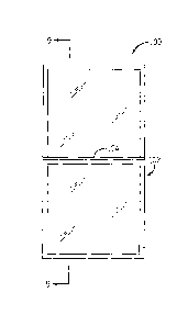
[0005] Figure I shows a plan view of a window with a continuous handle.
[0006] Figure 2 shows the top rail of a lower sash of the window of Figure 1
with the
continuous handle in the closed position.
[0007] Figure 3 shows the top rail of the lower sash with the continuous
handle in the
open position.
[0008] Figure 4 shows a top view of the top rail of the lower assembly of the
window.
[0009] Figure 5 is a cross-sectional view of the handle and upper rail of
Figure 4 taken
generally along lines 5-5 when the handle is in the closed position.
100101 Figure 6 is a cross-sectional view of the handle and upper rail of
Figure 4 taken
generally along lines 5-5 when the handle is in the open position.
[0011] Figure 7 is a cross-sectional view of the handle and upper rail of
Figure 4 taken
generally along lines 7-7 when the handle is in the closed position
[0012] Figure 8 is a cross-sectional view of the handle and upper rail of
Figure 4 taken
generally along lines 7-7 when the handle is in the open position.
[00131 Figure 9 is a cross sectional view of the window of Figure 1 generally
along the
lines 9-9.
[0014] Figure 10 is a cross sectional view of the window of Figure 1 taken
generally
along lines 9-9 with the sashes moved from the closed position.
[0015] Figure 11 is a sliding window having a continuous handle.
[0016] Figure 12 is a pivot latch in the engaged position.
[0017] Figure 13 is a pivot latch in the disengaged position.
[0018] Figure 14 is a cross sectional view of the window of Figure 1 taken
generally
along lines 9-9 with the lower sash pivoted to an open position.
3
CA 02846179 2014-03-14
DETAILED DESCRIPTION OF THE EXAMPLE EMBODIMENTS
[0019] Referring to Figure 1, a window 100 includes a first or lower sash 102
having a
continuous handle 104. In one embodiment window 100 is a single or double hung
window with a lower sash 102 that moves vertically between a closed position
and an
open position. Referring to Figure 11, a continuous handle may also be used on
a sliding
window that slides horizontally. The window 100 will be described as a single
or double
hung window but the continuous handle may also be used in a sliding window.
[0020] The directions used herein reflect the orientation of a user facing the
window
from the interior of an enclosure. Inwardly includes the direction away from
the window
towards the user and the interior of an enclosure, up and down include the
direction away
from and toward the direction of gravity, while left and right include the
direction as
viewed by a user facing the window from the interior of an enclosure. The
front will
include facing the interior of the enclosure while the back will include the
region facing
away from the enclosure when the window is in the installed closed
orientation.
[0021] Referring to Figure 2 lower sash 102 includes an upper rail 106 that
pivotally
supports continuous handle 104. Continuous handle 104 extends substantially
the entire
length of upper rail 106 from a first or leftward end 108 to the second or
rightward end
110 of upper rail 106. In one embodiment, continuous handle 104 extends along
the
entire length of upper rail 106, while in another embodiment handle 104
extends less than
the entire length of upper rail 106. It is contemplated that handle 104 may
extend more
than one half of the entire length, or less than one half of the entire
length. In another
embodiment, handle 104 extends from one end of rail 106 to the center region
of rail 106
in a manner that the handle 104 is not symmetrical along rail 106.
100221 Referring to Figures 4-6 continuous handle 104 includes a front edge
112 and an
opposing rear edge 114 having a pivot member 116 that operatively pivots
within a
groove 118 of upper rail 106. Referring to Figure 5 the front edge 112 of
continuous
handle 104 includes a lip 120 positioned below an upper surface 122. Rear edge
114
includes a downwardly extending wall portion 124 terminating in an arcuate
pivot
4
member 116. Rear edge 114, wall portion 124 and pivot member 116 extend
substantially the entire length of continuous handle 104 and upper rail 106.
[0023] Referring to Figure 5 continuous handle 104 includes a pair of flanges
126
extending from a bottom surface 128 connecting a downward member 130 that
operatively engages a lock 132. In a preferred embodiment lock 132 includes a
lock of
the type disclosed in US patent 8,182,001 entitled Direct Action Window Lock.
The lock disclosed in US Patent
8,182,001 ("the '001 patent") maintains the handle in an open or raised
position when the
sash is moved away from closed position. In this manner the top of the rail
106 is fully
exposed allowing the user to have free access to each of the pivot latch 134,
136 without
the need to hold open the continuous handle 104.
[00241 Pivot latches 134, 136 may be of the type having a slidable bolt 138
portion
connected to a button or slide 140 located in and accessible through a
depression in the
top surface of rail. In another embodiment pivot latch 134, 136 may be of the
type
described in co-pending published patent application No.2011/0192089 entitled
Window
Tilt Latch System ("the '089 publication").
The latches disclosed in the '089 publication allow the latches to remain in
an
open withdrawn position while the window is tilted away from the frame and/or
second
sash and automatically moves to the closed or extended position when the sash
is tilted
back to the closed non-tilted orientation.
100251 Referring to Figure 1 and Figure 5 handle 104 is in the lowered closed
position
covering both the top surface of upper rail 106 as well as covering the
buttons or slide
handle that activates the bolts of latches 134 and latch 136. Referring to
Figure 6, handle
104 is raised by a user by pushing member 120 upward and outward about pivot
116. As
handle 104 is pivoted from the closed to open positions the lock bolt member
is
withdrawn from the second sash and/or frame thereby allowing the lower sash to
be
raised relative to the second sash and/or frame as shown in Figure 11.
10026] As discussed above when a direct action lock of the type described in
the '001
patent is employed, handle 104 will remain in the raised position while the
sash is moved
CA 2846179 2019-01-11
CA 02846179 2014-03-14
from the closed position. This allows the user to have free access to each of
the tilt
latches 134, 136 without the need to simultaneously hold up the handle.
[0027] A user may then release the tilt latch bolts from the frame by either
activating a
button by pushing downward, or activating a slide by sliding horizontally
toward the
other tilt latch. Once the slide latch bolts have been withdrawn the sash may
be tilted
inwardly as illustrated in Figure 15.
[0028] The handle 104 is typically the length of an entire side of a sash 102
of the
window 100. In one embodiment sash 102 includes a pair of stiles 142 that are
spaced
apart and perpendicular to upper rail 106. Each stile having a first edge
adjacent the
glazing and a second edge distal the glazing. In one embodiment handle 104 has
a length
that is greater than the distance between the first edges of the first and
second stiles.
Stated another way handle 104 extends over at least a portion of both stiles
when the
handle 104 is in the first lowered position.
[0029] The application of hand pressure can be applied anywhere along the
entire length
of the handle 104 to activate lock 132 to unlock sash 102 from the second sash
and/or
frame. Pivoting handle 104 operates to unlock lock member 132. In the lowered
position, the entire latch assembly and lock assembly are hidden from view
providing a
clean look as well as making cleaning of the upper exposed surfaces easier by
providing a
continuous uninterrupted surface.
[00301 The lip 120 of the continuous handle 104 further provides the lifting
capability to
open or unlocked the sash 102 about the pivot 116 in groove 118. Once the
latch of lock
132 has been disengaged a user may continue to assert an upward pressure on
lip 120 to
raise sash 102 relative to the second sash and/or the frame. When lowering
sash 102, a
user may push down on handle 104 forcing the handle to the closed position
while
lowering the sash 102 to its original closed and lowered position. As
described in the
'001 patent, the handle 104 may be lowered without triggering the lock bolt
back to its
locked position. The lock bolt will automatically extend into the second sash
and/or
frame only once the lower sash is in the proper position relative to the
second sash and/or
frame.
6
CA 02846179 2014-03-14
[0031] Referring to Figure 3, in one embodiment upper rail 106 includes a
front wall 150
that terminates in a lower inwardly extending ridge 152. Similarly, an
inwardly upper
inwardly extending ridge extends from the top surface of upper rail 106. Front
wall 150
includes an opening 160 configured to receive lock 132 for installation
purposes. A
cover plate (not shown) may be secured to apertures 162, 164 in lock 132. In
one
embodiment apertures 162, 164 may include a female thread to receive a
threaded
fastener to secure a cover plate over aperture 160. In another embodiment, a
decorative
covering may extend the entire length of the upper rail 106 and extend between
the top of
rail 106 and the lower ridge 152. In one embodiment the decorative covering
may be a
wood or wood composite material selected to match the wood trim of the window
opening and/or window. The decorative covering may also be operatively secured
to the
upper rail with a fastener that may be received within apertures 162, 164 of
lock 132.
Alternatively, the decorative covering may be secured to upper rail 106
directly with
fasteners as are known in the art. Apertures 156, 158 may be used to secure an
upper
portion of lock 132 to upper rail 106. Aperture 166 provides an opening for
handle
member 130 to extend through the upper rail 106 to connect the continuous
handle 104
with lock 132.
[0032] Referring to Figure 11, a window 200 similar to window 100, only that
the
window sash 202 slides horizontally. The continuous rail 204 extends
vertically instead
of horizontally as with window 100. However, the continuous rail 204 operates
in the
same manner as continuous rail 104 with the components being orientated 90
degrees
clockwise from the components of the single or double hung window 100. The
same
principles and operations that apply to the vertical sliding window 100, also
apply to
window 200 that slides horizontally. In one embodiment window 200 may include
pivot
latches similar to pivot latches 134, 136. However in another embodiment
window 200
may include a single pivot latch located on the upper portion of movable sash
202. The
single pivot latch may permit sash 202 to be removed from window 200. Finally
it is also
contemplated that window 200 may not include a pivot latch. The horizontal
window 202
may be located above a kitchen sink or sufficiently high off of the ground
that it may be
7
CA 02846179 2014-03-14
difficult for some individuals to effectively reach a conventional lock
located in the
middle of the vertical rail. Continuous rail 204 allows for activation of a
lock distal from
the lower portion of sash 202 by pivoting a lower portion of rail 204. In this
manner,
activation of the lock between locked and unlocked positions is permitted
without the
need to reach to the middle of sash 202 as measured from the lower portion of
sash 202 to
the upper portion of sash 202. As discussed above with respect to handle 104,
the lock
disclosed in US Patent 8,182,001 ("the '001 patent") will maintain handle 204
in a raised
position when the sash is moved away from the closed position. In the
orientation of
window 200 handle 204 will pivot such that the free end of handle 204 will
extend to the
right toward the second sash and remain in that rightwardly extended position
while sash
202 is in the open position. Referring to Figure 11, sash 202 will slide to
the right in the
open position. Handle 204 will pivot back to the original position away from
the second
sash when the sash is returned to the left / closed position and the lock is
activated. It is
also contemplated that other locks known in the art' may be used in
combination with
continuous handle 104 and/or handle 204.
[00331 It is important to note that the construction and arrangement of the
latch
mechanism as described herein is illustrative only. Although only a few
embodiments of
the present inventions have been described in detail in this disclosure, those
skilled in the
art who review this disclosure will readily appreciate that many modifications
are
possible (e.g., variations in sizes, dimensions, structures, shapes and
proportions of the
various elements, values of parameters, mounting arrangements, use of
materials, colors,
orientations, etc.) without materially departing from the novel teachings and
advantages
of the subject matter recited in the claims, For example, elements shown as
integrally
formed may be constructed of multiple parts or elements and vice versa, the
position of
elements may be reversed or otherwise varied, and the nature or number of
discrete
elements or positions may be altered or varied. Accordingly, all such
modifications are
intended to be included within the scope of the present invention as defined
in the
appended claims. The order or sequence of any process or method steps may be
varied or
re-sequenced according to alternative embodiments. Other substitutions,
modifications,
8
CA 02846179 2014-03-14
changes and omissions may be made in the design, operating conditions and
arrangement
of the exemplary embodiments without departing from the scope of the present
inventions as expressed in the appended claims.
9