Note : Les descriptions sont présentées dans la langue officielle dans laquelle elles ont été soumises.
CA 02846710 2014-03-14
1
Gas Distribution Trailer for Natural Gas Delivery to Engines
CROSS REFERENCE TO RELATED APPLICATIONS
[0001] This application claims priority benefit to U.S. Provisional Patent
Application No.
61/798,768, filed March 15, 2013, and entitled "Gas Distribution Trailer for
Natural Gas Delivery to
Engines," the entire disclosure of which is incorporated herein by reference.
BACKGROUND
[0002] The following relates generally to gas distribution systems and,
more specifically, to a
portable gas distribution system configured to distribute fluid from a fluid
source to a number of
locations at a hydrocarbon well site.
[0003] Hydrocarbon well completion technology has evolved drastically over
the last decade,
increasing oil and gas reserves and improving well performance. One technique
of well completion
is to perforate with special "perf guns" in a hydrocarbon producing zone,
often over 10,000 feet
below the surface, and pump a combination of water and sand to fracture the
producing zone and
prop channels open to enable extraction of hyrdocarbons. As the technique has
evolved, one
effective and economic technique has proven to be high pressure, high volume
hydraulic fracturing
jobs (often called "frac'ing" or "pressure pumping"). The use of as many as
twenty semi-truck
mounted, diesel engine driven positive displacement pumps, often operating 24
hours per day, year
round, has become a common occurrence to provide pumping required to operate
such sites. Such
operations can result in the consumption of relatively large quantities of
diesel fuel.
[0004] As drilling and completion technology has developed, one result has
been that natural gas
production has increased, thus increasing the domestic supply and driving the
market demand and
price of the commodity. This has increased the attractiveness of utilizing
natural gas as a fuel in
operations of oil and gas drilling sites. Dual fuel (blending natural gas and
diesel fuel on engine) has
proven to be one viable solution in pressure pumping services to reduce the
amount of diesel fuel
consumed, reduce engine emissions, and reduce completion costs.
[0005] While many producers may desire to utilize natural gas in
completion operations, a
significant challenge with pressure pumping services is delivering sufficient
quantities of natural gas
CA 02846710 2014-03-14
2
at an acceptable flow rate on many different locations, all with different
layouts, and with limited
time to rig up and rig down equipment. Furthermore, it is desirable for a fuel
delivery system in
pressure pumping operations to be flexible and allow adjustment to each
individual site. An
adaptable fuel delivery system developed for pressure pumping operations can
be utilized in many
different operational areas, across industries where multiple engines need
hydrocarbon delivery
from a single source of fuel. To date, fuel delivery for this application has
been in the form of steel,
rigid pipe protected by a steel enclosure. Each section of pipe and protective
covering can be bulky,
heavy and has limited flexibility to adapt to changing locations. From the
rigid pipe, there is a run of
flexible pipe that is run from the rigid manifold to an engine that is to
receive the fuel. Such fuel
delivery techniques may be relatively inefficient and require significant
resources to set up and
modify.
SUMMARY
[0006] The described features generally relate to one or more improved
systems, apparatuses,
and/or methods, for fluid distribution utilizing a mobile fluid distribution
platform. In some aspects,
a fluid distribution apparatus includes a trailer having a central platform
and one or more sets of
wheels. The central platform may include two or more hose reels mounted
thereto, each of the
hose reels including a reel that is rotatable about a rotation axis and a
fluid distribution hose
windable around the reel. The rotation axis of each of the hose reels may be
generally parallel to a
longitudinal axis of the central platform. The central platform may also
include a manifold coupled
with each of the hose reels and couplable with an external fluid source, such
as a natural gas fuel
source. The manifold may provide fluid from the external fluid source to each
of the fluid
distribution hoses of the respective hose reels.
[0007] Further scope of the applicability of the described methods and
apparatuses will become
apparent from the following detailed description, claims, and drawings. The
detailed description
and specific examples are given by way of illustration only, since various
changes and modifications
within the spirit and scope of the description will become apparent to those
skilled in the art.
BRIEF DESCRIPTION OF THE DRAWINGS
[0008] A further understanding of the nature and advantages of the present
invention may be
realized by reference to the following drawings. In the appended figures,
similar components or
features may have the same reference label. Further, various components of the
same type may be
distinguished by following the reference label by a dash and a second label
that distinguishes among
CA 02846710 2014-03-14
3
the similar components. If only the first reference label is used in the
specification, the description is
applicable to any one of the similar components having the same first
reference label irrespective of
the second reference label.
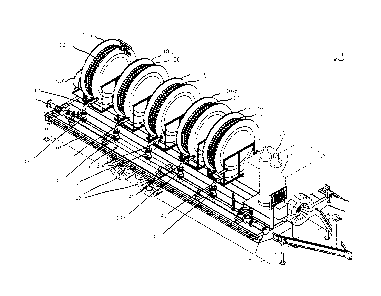
[0009] FIG. 1 shows a front and right-side perspective view of a fluid
distribution trailer according
to various aspects of the disclosure;
[0010] FIG. 2 shows a front and left side perspective view of the fluid
distribution trailer according
to various aspects of the disclosure;
[0011] FIG. 3 shows a rear and left side perspective view of the fluid
distribution trailer according
to various aspects of the disclosure;
[0012] FIG. 4 shows a right side view of the fluid distribution trailer
according to various aspects
of the disclosure;
[0013] FIG. 5 shows a left side view of the fluid distribution trailer
according to various aspects of
the disclosure;
[0014] FIG. 6 shows a front view of the fluid distribution trailer
according to various aspects of the
disclosure;
[0015] FIG. 7 shows a rear view of the fluid distribution trailer
according to various aspects of the
disclosure;
[0016] FIG. 8 shows a top plan view of the fluid distribution trailer
according to various aspects of
the disclosure; and
[0017] FIG. 9 shows a diagram of a fluid distribution apparatus according
to various aspects of the
disclosure.
DETAILED DESCRIPTION
[0018] Techniques are described for gas distribution utilizing a portable
distribution system that
provides flexible and readily adaptable configurations for delivery of fuel
from a fuel source to
several locations at a particular site. The inventors of the present
disclosure have recognized that,
particularly with respect to completion operations at hydrocarbon drilling
sites, pumps need to be
oriented in a specific and consistent manner at each location. Such pumps are
often mounted on
CA 02846710 2014-03-14
4
trucks, or trailers, are use internal combustion engines to power the pumps.
Previously such
operations used a hard-piped manifold that would run along the rear of the
trucks, or trailers, on
which the pumps are mounted so as to reduce the likelihood that the piping
would be driven over.
[0019]
However, such techniques often locate the gas line in the highest risk area on
a pressure
pumping location. Specifically, this location is where the high pressure water
is pressurized up to
15,000 psi for injection as part of the completion operations. Additionally,
such techniques provide
for piping that cannot be easily moved, often requires multiple trucks to
relocate, and lacks
adaptability required for efficient use at different locations.
Furthermore, such hard-piped
manifolds distribution pipes are heavy to transport, requiring multiple heavy
duty trucks for
transporting the hardware for a single site. Additionally, such systems can
take a significant amount
of time to set up, costing valuable time that could be otherwise used for
pumping. Furthermore, this
method also requires that a set section of pipe and flexible pipe fits each
site. In order to ensure
that suitable pipes and flexible pipe fits are available for a particular
site, such techniques require
multiple sections and sizes of extra pipe to be transported and stored on
location, to allow for
changing locations of one or more pumps as occasionally required at a site.
Ultimately, this is not a
flexible design..
[0020]
According to various aspects of the present disclosure, as will be described
in more detail
below, a fluid distribution apparatus may include a trailer having a central
platform and one or more
sets of wheels. The central platform may include two or more hose reels
mounted thereto, each of
the hose reels including a reel that is rotatable about a rotation axis and a
fluid distribution hose
windable around the reel. The rotation axis of each of the hose reels may be
generally parallel to a
longitudinal axis of the central platform. The central platform may also
include a manifold coupled
with each of the hose reels and couplable with an external fluid source, such
as a natural gas fuel
source. The manifold may provide fluid from the external fluid source to each
of the fluid
distribution hoses of the respective hose reels. According to some aspects,
one or more of the fluid
distribution hoses may be coupled with an engine of a positive displacement
pump. The positive
displacement pump(s) may be coupled with a hydraulic fracturing fluid source
and may pump the
hydraulic fracturing fluid into a hydrocarbon producing well as part of the
completion operations for
the well. The engine(s) of the positive displacement pump(s) may be, for
example, dual fuel engines
capable of operating using a mixture of diesel fuel and natural gas.
[0021]
Thus, the following description provides examples, and is not limiting of the
scope,
applicability, or configuration set forth in the claims. Changes may be made
in the function and
CA 02846710 2014-03-14
arrangement of elements discussed without departing from the spirit and scope
of the disclosure.
Various examples may omit, substitute, or add various procedures or components
as appropriate.
For instance, the techniques described may be performed in an order different
from that described,
and various steps may be added, omitted, or combined. Also, features described
with respect to
5 certain examples may be combined in other examples.
[0022] Referring first to FIGS. 1-9, a gas distribution trailer 100
according to various aspects is
discussed. The trailer 100 may be used in hydrocarbon well drilling and
completion operations, for
example, to distribute fluid (gas or liquid), such as natural gas, from a
central fluid storage unit to
individual units in need of the fluid, such as pump engines that operate
positive displacement pumps
that pump hydraulic fracturing fluid into hydrocarbon producing wells, for
example. The distribution
trailer 100 may include a central platform 105 on top of which are positioned
one or more circular
hose reels 110a through 110-f. The central platform 105 has a length and a
width, and in certain
examples the length is greater than the width and a longitudinal axis
extending along the length of
the central platform. The distribution trailer further includes a manifold 115
which transports fluid
from the central fluid storage unit to each individual circular hose reel 110.
Each hose reel 110
includes a hose 120 which can be unwound from the hose reel and connected with
a unit in need of
fluid, such as an internal combustion engine that requires fuel for operation.
[0023] The central platform 105 of the distribution trailer100 can be
provided with wheels 125
such that the entire unit 100 is mobile. Any number of wheels 125 can be used
and can be
positioned in any of a variety of locations. The length and width of the
central platform 105 is
generally not limited. In some embodiments, the length and width of the
trailer 100 is within the
dimensions allowing the trailer 100 to be safely and legally transported on
public roads. The
dimensions of the trailer 100 can also be adjusted to accommodate the size of
the hose reels 110.
For example, when numerous hose reels 110 are used on the trailer 100, the
length of the trailer 100
can be extended to accommodate the extra hose reels 110. Similarly, when the
diameter of the
hose reels 110 is increased, the width of the trailer 100 can be increased so
that none of (or only a
small portion of) each hose reel 110 extends over the edge of the trailer 100.
[0024] Any number of circular hose reels 110 can be positioned on and
secured to the central
platform 105. In some embodiments, the number of circular hose reels 110 is in
the range of from 2
to 6. The circular hose reels 110 can be positioned perpendicular to the
longitudinal axis of the
central platform 105. In this configuration, pulling the hoses 120 off each
hose reel 110 leads to the
hoses 120 extending off of the lateral sides of the trailer 100. The diameter
of each hose reel 110 is
CA 02846710 2014-03-14
6
not limited, and may be adjusted to accommodate the length of the hose 120
associated with the
hose reel. In some embodiments, all of the hose reels 110 on the trailer 100
are identical. In some
embodiments, different size hose reels 110 are used on the same trailer 100,
such as illustrated with
hose reel 1104, for example.
[0025] Each hose reel 110 includes a fluid passage the extends from an
exterior position to an
interior position of the hose reel 110. The exterior position is provided so
that the hose reel 110 can
be fluidly connected to the manifold 115 described in greater detail below.
The interior position is
provided so that the hose 120 can be fluidly connected to the hose reel 110.
Fluid passing from the
manifold 115 to the hose reel 110 travels through the fluid passage and into
the hose 120.
[0026] As noted above, each hose reel 110 includes a hose 120, which may be
made of a flexible
material. The hose 120 wound on each hose reel 110 can be pulled out and
connected with an
individual unit in need of fluid, and can be wound back up on the reels 110
when not in use. In some
embodiments, the length of the hose 120 is sufficiently long so as to reach a
unit in need of fluid
positioned a distance away from the distribution trailer 100. Any suitable
hose length can be used.
In some embodiments, the hose length is 150 feet. An electric motor can be
used to assist with
winding and unwinding the hoses 120 on the hose reels 110. The electric motors
for the hose reels
110 may be powered by an electric generator 130 located on the central
platform 105, in some
examples. Additionally, or alternatively, mechanical handles may be used
either as primary or
secondary means for winding and unwinding the hose 120.
[0027] The type of hose 120 provided on each hose reel 110 is generally not
limited and can be
adjusted based on the specific application of the distribution trailer 100.
For example, when the
hose 120 is used to transport natural gas, a hose suitable for transporting
natural gas is used. The
material, thickness, and diameter of the hose 120 can be adjusted based on the
fluid being
transported through the hose 120 and other factors. The distal end of the hose
120 can include any
of a variety of attachment mechanisms so that the hose can be attached to the
unit in need of fluid.
In some embodiments, the hose 120 includes a quick connect mechanism that
allows for fast
attachment and detachment of the hose to the unit in need of fluid. The
proximal end can also
include an attachment mechanism for attaching the hose 120 to the hose reel
110.
[0028] The distribution manifold 115 provided on the trailer can be
positioned along the length of
a lateral side of the central platform 105. The manifold 115 includes
individual extensions 135 that
are roughly aligned with each hose reel 110, according to certain examples.
The extensions 135 may
CA 02846710 2014-03-14
7
transport fluid from the central manifold 115 piping to each hose reel 110.
Valves 140 can be
provided at the juncture between the central manifold 115 piping and the
extensions 135 so that
extensions 135 can be turned off and on depending on whether the extension is
connected with a
hose reel 110, or depending upon a particular hose reel 110 is being used to
deliver fluid through its
associated hose 120.
[0029] The dimensions and materials of the distribution manifold 115 are
generally not limited
and can be adjusted based on the specific application of the trailer 100. For
example, when the
trailer 100 is being used to supply natural gas, the distribution manifold 115
can be made from a
material suitable for transporting natural gas and having suitable dimensions
for transporting natural
gas, such as, for example, 3 inch stainless steel piping for the main manifold
115 pipe with 2 inch
stainless steel piping used for the extensions 135. Of course, other suitable
materials can be used
based on the application and materials to be supplied, as will be readily
recognized by one of skill in
the art.
[0030] At one end, the distribution manifold 115 may be connected to the
central fluid storage
unit through a fluid connection 145 so that fluid can be transported from the
central fluid storage
unit to and through the manifold 115. At the other end, the distribution
manifold 115 may include a
blind 150 that may be removed and coupled to, for example, another gas
distribution trailer 100.
Fluid running through the manifold 115 will travel up to each hose reel 110
via the individual
connections 135 between each hose reel 110 and the manifold 115. Once the
fluid flows up to the
hose reel 110, the fluid then travels into the hose 120 wound on each hose
reel 110. In some
examples, a vent 160, as may best be seen in FIG. 8, may be coupled with the
manifold 115 at one or
more locations, such as at each extension 135, and may connect to a vent stack
and remote vent. In
certain examples, one or more nitrogen tanks 165 may be coupled with the
manifold 115, and may
be used to purge the manifold 115 and/or one or more connections or hoses.
[0031] In a specific application, illustrated in FIG. 9, a system 200 may
include a distribution
trailer 100-a may be used to provide natural gas from a natural gas source 205
to a pumping system
300 that includes, in certain examples, duel fuel engines 305 powering
frac'ing pumps 310 that may
pump hydraulic fracturing fluid 315 to a hydrocarbon well 320. The natural gas
may be provided
from natural gas source 205 to the individual hose reels 210 via manifold 215
that may include
extensions 235 and valves 240, similarly as discussed above. The natural gas
is distributed to each of
the hose reels 210 and moves through the corresponding hoses 220. Each hose
220 may be
connected to an individual duel fuel engine 305 so that natural gas can be
provided through the hose
CA 02846710 2014-03-14
8
220 to the engine 305. In the example of FIG. 9, a number of pressure gauges
255 may be present at
various locations on the manifold 215 (also illustrated in the examples of
FIGS. 1-8 as 155).
Additionally, a vent 260 may be coupled with the manifold 115 at one or more
locations (such as at
each extension 235) and may connect to a vent stack and remote vent, similarly
as discussed above.
[0032] The advantages of a gas distribution trailer such as described
herein include portability
and adaptability. In some examples, the trailer may be moved with a single
truck, although it will be
understood that other examples may be embodied on a skid that may also be
transported. Certain
examples include multiple large hose reels with 150 foot sections of flexible
gas hose that can be
pulled out to the length needed and reeled back in when a truck/pump needs to
be pulled out. The
trailer can be mobilized and moved at any time during the pressure pumping
operation making a site
adaptable solution. Furthermore, it may be operated by a single person and
does not require any
special equipment to move in some embodiments. An electric motor may be used
to retract the
hose on the reel with a mechanical handle backup, providing flexibility and
ease of use. Each hose
end may include a quick connect end to quickly hook up to a pump engine, for
example. In some
examples, embodiments provide relatively easy and quick setup, as a person may
park the trailer
outside of the pumping area in a "safe zone" and pull hoses to desired
locations. The set-up may
occur at any point in the operation, as the trailer merely needs to be parked
and then hook up can
commence. Unlike the previously used single rigid pipe set up described above,
in which the piping
runs the distance of the trucks (pressurized with natural gas), this trailer
is adaptable to as many
engines needed. Natural gas can be provided in whichever line or lines are
desired, with no need to
fill the entire manifold. Increasing its adaptability, this trailer can
connect multiple gas distribution
trailers in series to expand the number of reels and engines available for
gas. Finally, the trailer is
designed to have easy access to additional safety devices with a common vent
line to vent stack on
trailer and a remote vent.
[0033] The previous description of the disclosure is provided to enable a
person skilled in
the art to make or use the disclosure. Various modifications to the disclosure
will be readily
apparent to those skilled in the art, and the generic principles defined
herein may be
applied to other variations without departing from the spirit or scope of the
disclosure.
Throughout this disclosure the term "example" or "exemplary" indicates an
example or
instance and does not imply or require any preference for the noted example.
Thus, the
disclosure is not to be limited to the examples and designs described herein
but is to be
CA 02846710 2014-03-14
9
accorded the widest scope consistent with the principles and novel features
disclosed
herein.
[0034] What is claimed is: