Note : Les descriptions sont présentées dans la langue officielle dans laquelle elles ont été soumises.
1
[DESCRIPTION]
[TITLE OF INVENTION]
BOTTLE
[Technical Field]
[0001]
The present invention relates to a bottle.
[Background Art]
[0002]
Conventionally, as a bottle formed of a synthetic resin material in a shape of
a bottomed
tube, as set forth in, for instance, Patent Document 1 below, a bottle having
a constitution
in which a bottom wall part of a bottom part includes a grounding part that is
located at
an outer circumferential edge, a standing peripheral wall part that is
connected from a
bottle radial inner side to the grounding part and extends upward, a movable
wall part
that protrudes from an upper end of the standing peripheral wall part toward
the bottle
radial inner side, and a depression peripheral wall part that extends upward
from a bottle
radial inner end of the movable wall part has been known. In the known
constitution, the
movable wall part rotates about a portion connected to the standing peripheral
wall part
so as to cause the depression peripheral wall part to move upward, and thereby
a pressure
reduced in the bottle is absorbed.
[Citation List]
[Patent Literature]
[0003]
[Patent Document 1]
CA 2847225 2018-08-09
CA 02847225 2014-02-24
2
PCT International Publication No. W02010/061758
[Summary of Invention]
[Means for solving the Problem]
[0004]
However, the conventional bottle leaves room for improvement in increasing
performance of absorbing the pressure reduced in the bottle.
Here, to increase the reduced-pressure absorption performance, it is necessary
to
secure an amount of upward movement of the movable wall part. To do so, at the
portion connected between the movable wall part and the standing peripheral
wall part, it
.. can be taken into account that an angle (angle of depression) between a
tangential line of
the movable wall part and a horizontal plane is increased, for instance, to
about 45
degrees with respect to the horizontal plane, and that the movable wall part
is formed to
be located as low as possible. However, in this case, it is easy to secure the
amount of
upward movement of the movable wall part, but there is a problem in that it is
difficult
for the movable wall part to move upward.
[0005]
Accordingly, the present invention has been made in consideration of these
circumstances, and an object of the present invention is to provide a bottle
in which
improvement in performance of absorbing a pressure reduced in the bottle is
attempted to
allow a movable wall part to move smoothly.
[Means for solving the Problem]
[0006]
To solve the above-mentioned problem, the present invention proposes the
following means.
According to a first aspect of the present invention, a bottle that is
tubular, is
CA 02847225 201,4-02-24
3
formed of a synthetic resin material, and has a bottom part. A bottom wall
part of the
bottom part includes a grounding part that is located at an outer
circumferential edge
thereof, a standing peripheral wall part which is connected, from a radial
inner side of the
bottle, to the grounding part and which extends upward, a movable wall part
that
protrudes from an upper end of the standing peripheral wall part toward the
radial inner
side of the bottle, and a depression peripheral wall part that extends upward
from an
inner end of the movable wall part in a radial direction of the bottle. The
movable wall
part is disposed so as to be movable upward centering on a portion connected
to the
standing peripheral wall part along with the depression peripheral wall part.
An upward
swelling part which swells upward is formed at an outer end along the radial
direction of
the bottle of the movable wall part.
[0007]
With this configuration, when the movable wall part moves centering on the
portion connected between the movable wall part and the standing peripheral
wall part,
the upward swelling part becomes a starting point when the movable wall part
moves for
the first time. In this case, the upward swelling part begins to move upward
depending
on a change in an internal pressure of the bottle. Thereby, in accordance with
the
movement, the entire movable wall part moves upward. As a result, it is
possible to
smoothly move the entire movable wall part depending on the change in the
internal
pressure of the bottle.
Accordingly, in the portion connected between the movable wall part and the
standing peripheral wall part, even when an angle (depression angle) between a
tangential line of the movable wall part and a horizontal plane is increased
to improve the
reduced-pressure absorption performance, it is possible to inhibit difficulty
in the upward
movement of the movable wall part. As a result, it is possible to improve the
4
perfoimance of absorbing the pressure reduced in the bottle and then to
smoothly move
the movable wall part.
[0008]
Further, a downward swelling part which is recessed downward may be formed in
the
movable wall part at a position where is at more inner side in the radial
direction of the
bottle than the upward swelling part.
[0009]
In this case, a length from an outer end to an inner end of the movable wall
part in a
radial direction of the bottle is longer than a tangential length of a virtual
line that extends
along a surface shape of the movable wall part connecting an inner end of the
standing
peripheral wall part in the radial direction of the bottle and an outer end of
the depression
peripheral wall part in the radial direction of the bottle. Thereby, it is
possible to secure
an amount of movement of the movable wall part and to further improve the
reduced-
pressure absorption performance.
[0009a]
According to one aspect, there is provided a bottle that is tubular, is formed
of a synthetic
resin material, and has a bottom part, wherein a bottom wall part of the
bottom part
includes: a grounding part which is located at an outer circumferential edge
thereof; a
standing peripheral wall part which is connected, from an inner side of a
radial direction
of the bottle, to the grounding part and which extends upward; a movable wall
part which
CA 2847225 2018-08-09
4a
protrudes from an upper end of the standing peripheral wall part toward the
inner side of
the radial direction of the bottle; and a depression peripheral wall part
which extends
upward from an inner end of the movable wall part along the radial direction
of the
bottle, wherein the movable wall part is arranged so as to be movable upward
centering
on a curved surface part connected to the standing peripheral wall part along
with the
depression peripheral wall part, wherein an upward swelling part which swells
upward in
a normal direction of the movable wall part when viewed from a longitudinal
cross
section in a direction along an axis of the bottle, and the upward swelling
part is formed
at an outer end along the radial direction of the bottle of the movable wall
part, wherein
the upward swelling part is located above a virtual line that extends along a
surface shape
of the movable wall part connecting a radial inner end of the curved surface
part and a
radial outer end of the depression peripheral wall part, and wherein a top of
the upward
swelling part is located below the curved surface part connected to the
standing
peripheral wall part.
[Advantageous Effects of Invention]
[0010]
According to the foregoing bottle, the improvement in the performance of
absorbing the
pressure reduced in the bottle is attempted to allow the movable wall part to
move
smoothly.
[Brief Description of Drawings]
[0011]
FIG. 1 is a front view of a bottle in an embodiment of the present invention.
FIG. 2 is a bottom view of the bottle in the embodiment of the present
invention.
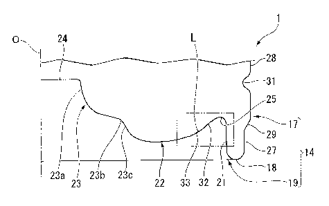
FIG. 3A is a cross-sectional view taken along line A-A of FIG. 2.
FIG. 3B is an enlarged view of a portion surrounded by a chain double dashed
CA 2847225 2018-08-09
CA 02847225 2014-02-24
line of FIG. 3A.
[Description of Embodiments]
[0012]
Hereinafter, a bottle according to an embodiment of the present invention will
be
5 described with reference to the drawings.
As shown in FIG 1, a bottle 1 according to the present embodiment includes a
mouth part 11, a shoulder part 12, a trunk part 13, and a bottom part 14, and
has a
schematic constitution in which these parts 11 to 14 cause respective central
axes thereof
to be placed on a common axis, and are continuously connected in this order.
[0013]
Hereinafter, the common axis is referred to as a bottle axis 0. In the
direction
of the bottle axis 0, a side of the mouth part 11 is referred to as an upper
side, and a side
of the bottom part 14 is referred to as a lower side. Further, a direction
perpendicular to
the bottle axis 0 is referred to as a radial direction, and a direction going
around the
.. bottle axis 0 is referred to as a circumferential direction.
The bottle 1 is integrally formed of a synthetic resin material by blow
molding
using a preform formed in a bottomed tubular shape by injection molding.
Further, a
cap (not shown) is mounted on the mouth part 11. Furthermore, each of the
mouth part
11, the shoulder part 12, the trunk part 13, and the bottom part 14 has a
circular shape
when viewed from a cross section perpendicular to the bottle axis 0.
[0014]
A first annular groove 16 is continuously formed in a portion connected
between
the shoulder part 12 and the trunk part 13 throughout the circumference of the
connected
portion.
The trunk part 13 is formed in a tubular shape, and between opposite ends
CA 02847225 201,4-02-24
6
thereof in the direction of the bottle axis 0, a diameter thereof is smaller
than those of the
opposite ends thereof A plurality of second annular grooves 15 are
continuously
formed in the trunk part 13 at intervals in the direction of the bottle axis 0
throughout the
circumference of the trunk part 13.
[0015]
A third annular groove 20 is continuously formed in a portion connected
between the trunk part 13 and the bottom part 14 throughout the circumference
of the
connected portion.
As shown in FIGS. Ito 3B, the bottom part 14 includes a heel part 17 whose
upper end opening is connected to a lower end opening of the trunk part 13,
and a bottom
wall part 19 which closes a lower end opening of the heel part 17 and whose
outer
circumferential edge serves as a grounding part 18, and is formed in a cup
shape
A fourth annular groove 31 is continuously formed in the heel part 17
throughout the circumference of the heel part 17. As shown in FIG. 1, a radial
depth of
the fourth annular groove 31 is equal to that of the third annular groove 20.
[0016]
As shown in FIG. 3A, the bottom wall part 19 includes a standing peripheral
wall part 21 that is connected to the grounding part 18 from a radial inner
side and
extends upward, an annular movable wall part 22 that protrudes from an upper
end of the
standing peripheral wall part 21 toward the radial inner side, and a
depression peripheral
wall part 23 that extends upward from an inner tip of a radial inner end 22a
of the
movable wall part 22.
[0017]
As shown in FIG. 3A, the standing peripheral wall part 21 is reduced in
diameter
from a bottom to a top.
7
The movable wall part 22 is formed in the shape of a curved surface that
protrudes
downward, and gradually extends downward from the radial outer side to the
radial inner
side. This movable wall part 22 and the standing peripheral wall part 21 are
connected
via a curved surface part 25 that protrudes upward. Thus, to cause the
depression
peripheral wall part 23 to move upward, the movable wall part 122 is formed so
as to
rotate (move) freely around the curved surface part (a portion connected to
the standing
peripheral wall part 21) 25 and cause the depression peripheral wall part 23
to move
upward.
[0018]
Here, an upward swelling part 32 swelling upward is formed at a radial outer
end 22b
thereof, that is, at a portion adjacent to the curved surface part 25 in the
movable wall
part 22. This upward swelling part 32 is fattued in the shape of a curved
surface that
protrudes in a normal direction of the movable wall part 22, and is formed in
the shape of
a ring that extends over the entire circumference of the circumferential
direction. To be
specific, the upward swelling part 32 is located above a virtual line L (e.g.,
a downward
inflated curved line or a straight line) that extends along a surface shape of
the movable
wall part 22 connecting a radial inner end of the curved surface part 25 and a
radial outer
end of the depression peripheral wall part 23. Further, the top of the upward
swelling
part 32 is located below the curved surface part 25. In addition, an angle
(depression
angle) 01 between a tangential line and a horizontal plane at a radial outer
end of the
upward swelling part 32 may be set to be smaller than 10 degrees or more with
respect to
an angle (depression angle) 01 between a tangential line and a horizontal
plane at a radial
outer end of the virtual line L. In the shown example, 01 is set to about 28
degrees, and
02 is set to about 44 degrees.
[0019]
CA 2847225 2018-08-09
CA 02847225 2014-02-24
8
Further, a downward swelling part 33 which is recessed downward is formed at
a position of the inner side of the radial direction than the upward swelling
part 32 in the
outer end 22b of the movable wall part 22. The downward swelling part 33 is
formed in
the shape of the curved surface that protrudes in the normal direction of the
movable wall
part 22, and is formed in the shape of a ring that extends over the entire
circumference of
the circumferential direction. To be specific, the downward swelling part 33
is located
below the above-mentioned virtual line L described above. In this case, the
above-mentioned upward swelling part 32 is configured so that the radial outer
end
thereof is continuously installed on the radial inner end of the curved
surface part 25, and
a radial inner end thereof is continuously installed on a radial inner end of
the radial outer
end of the downward swelling part 33.
[0020]
The upward swelling part 32 is formed with a smaller radius of curvature than
the above-mentioned downward swelling part 33. Further, when viewed from the
longitudinal cross section in the direction of the bottle axis 0, a length D1
of a tangential
line from the radial outer end to the radial inner end of the downward
swelling part 33 is
formed so as to be longer than a length D2 of a tangential line from the
radial outer end
to the radial inner end of the upward swelling part 32.
[0021]
The depression peripheral wall part 23 is arranged on the common axis with the
bottle axis 0, and is gradually increased in diameter from the top to the
bottom. A
disc-shaped top wall 24 disposed on the common axis with the bottle axis 0 is
connected
to an upper end of the depression peripheral wall part 23. A tubular shape
having the
top is formed by both of the depression peripheral wall part 23 and the top
wall 24. The
depression peripheral wall part 23 is formed in a circular shape when viewed
from the
CA 02847225 2014-02-24
9
cross section. Further, the depression peripheral wall part 23 is configured
so that an
upper end of a curved wall part 23a, which is formed in the shape of a curved
surface
protruding toward the radial inner side, is connected to the top wall 24, and
a lower end
of the curved wall part 23a is connected to an inclined wall part 23c via an
indented part
23b. The inclined wall part 23c is gradually increased in diameter from the
top to the
bottom, and a lower end thereof is connected to the inner tip of the radial
inner end 22a
of the annular movable wall part 22.
[0022]
In the present embodiment, in the heel part 17, a diameter of a lower heel
part 27
which is connected from the radial outer side to the grounding part 18 is
formed so as to
be smaller than a diameter of an upper heel part 28 which is connected from
above to the
lower heel part 27. The upper heel part 28 is a maximum outer diameter part of
the
bottle 1 along with the opposite ends of the trunk part 13 in the direction of
the bottle
axis 0.
[0023]
Furthermore, in the present embodiment, a connecting portion 29 between the
lower heel part 27 and the upper heel part 28 is gradually reduced in diameter
from the
top to the bottom. When viewed from the cross section, a shape of the
connecting
portion 29 extends from the top to the bottom in a linear shape.
[0024]
When the pressure in the bottle 1 configured in this way is reduced, the
movable
wall part 22 rotates about the curved surface part 25 of the bottom wall part
19 in an
upward direction. Thereby, the movable wall part 22 moves so as to lift the
depression
peripheral wall part 23 in an upward direction. In other words, the bottom
wall part 19
of the bottle 1 is positively deformed when the pressure is reduced, and
thereby a change
CA 02847225 2014-02-24
in the internal pressure (pressure reduction) of the bottle 1 can be absorbed
without
deformation of the trunk part 13. In this case, the portion connected between
the
standing peripheral wall part 21 and the movable wall part 22 is formed at the
curved
surface part 25 protruding upward, and thereby the movable wall part 22 is
allowed to
5 easily move (rotate) centering on the curved surface part 25. For this
reason, the
movable wall part 22 is allowed to be smoothly deformed depending on the
change in the
internal pressure of the bottle I.
[0025]
Especially, in the present embodiment, the upward swelling part 32 swelling
10 upward is formed on the movable wall part 22. Thereby, when the movable
wall part
22 moves centering on the curved surface part 25, the upward swelling part 32
becomes a
starting point when the movable wall part 22 moves for the first time. In this
case, the
upward swelling part 32 begins to move upward depending on the change in the
internal
pressure of the bottle 1. Accordingly, in accordance with the movement, the
entire
movable wall part 22 moves upward. Thereby, it is possible to smoothly move
the
entire movable wall part 22 depending on the change in the internal pressure
of the bottle
1.
Accordingly, even when the angle 02 between the tangential line of the movable
wall part 22 and the horizontal plane is increased to improve the reduced-
pressure
absorption performance, it is possible to inhibit difficulty in the upward
movement of the
movable wall part 22. As a result, it is possible to improve the performance
of
absorbing the pressure reduced in the bottle 1 and then to smoothly move the
movable
wall part 22.
[0026]
Furthermore, in the present embodiment, since a downward swelling part 33 is
CA 02847225 2014-02-24
11
formed at a position of the inner side of the radial direction than the upward
swelling part
32 in the movable wall part22, the length from the radial outer end 22b to the
radial inner
end 22a of the movable wall part 22 is longer than the length of the virtual
line L that
extends along the surface shape of the movable wall part 22. Thereby, it is
possible to
.. secure the amount of movement of the movable wall part 22 and to further
improve the
reduced-pressure absorption performance.
[0027]
While the embodiment of the present invention has been described in detail
with
reference to the drawings, a detailed constitution is not limited to this
embodiment, and
includes a change in design without departing from the gist of the present
invention.
[0028]
For example, when viewed from a cross section, the shapes of the upward
swelling part 32 and the downward swelling part 33 may be appropriately
changed in
design without being limited to the curved surface shape.
Further, the upward swelling part 32 and the downward swelling part 33 may be
intermittently formed in the circumferential direction.
Furthermore, a plurality of downward swelling parts 33 may be formed in the
radial direction. For example, the downward swelling parts 33 may be formed in
a
corrugated shape in the radial direction.
[0029]
Further, the standing peripheral wall part 21 may be appropriately modified,
for
instance, may extend in parallel in the direction of the bottle axis 0.
Furthermore, the depression peripheral wall part 23 may be appropriately
modified, for instance, may extend in parallel in the direction of the bottle
axis 0.
[0030]
CA 02847225 2014-02-24
12
Further, the synthetic resin material of which the bottle I is formed may be
appropriately changed into, for instance, polyethylene terephthalate,
polyethylene
naphthalate, amorphous polyester, or a blended material thereof.
Furthermore, the bottle 1 may have a laminated structure having a medium layer
without being limited to a single layer structure. This medium layer may
include, for
instance, a layer of a resin material having a gas barrier characteristic, a
layer of a
recycled material, or a layer of a resin material having oxygen absorbability.
In addition, in the embodiment, the shape of each of the shoulder part 12, the
trunk part 13, and the bottom part 14 when viewed from the cross section
perpendicular
to the bottle axis 0 has the circular shape, but it may be appropriately
modified into, for
instance, a polygonal shape without being limited thereto.
[0031]
In addition, without departing from the spirit of the present invention, the
components in the embodiment may be properly replaced by well-known
components,
and the above-mentioned modifications may be appropriately combined.
[Industrial Applicability]
[0032]
According to the foregoing bottle, the improvement in the performance of
absorbing the pressure reduced in the bottle is attempted to allow the movable
wall part
to move smoothly.
[Reference Signs List]
[0033]
1: bottle
14: bottom part
18: grounding part
CA 02847225 2014-02-24
13
19: bottom wall part
21: standing peripheral wall part
22: movable wall part
23: depression peripheral wall part
25: curved surface part
32: upward swelling part
33: downward swelling part