Note : Les descriptions sont présentées dans la langue officielle dans laquelle elles ont été soumises.
CA 02848327 2014-03-11
WO 2013/044916
PCT/DK2012/000104
HEAT LAMP
Field of the invention
The invention generally relates to a heat lamp. The invention more
particularly relates to an
electrical heat lamp for pigs, especially for small pigs and/or pig breeding.
Background of the invention
It is well known that new born and very young pigs require heat in order to
thrive and grow.
Therefore, heat lamps have been developed for the
pig farrowing industry with the purpose of keeping new born and young pigs
warm.
In traditional farrowing operations, it is desirable to heat, at least a part
of, the box areas. A
common method is to suspend a heat lamp over the box areas.
Prior art heat lamps for pigs typically use bulbs to generate heat, and when
the box area is
cleaned with the use of water, each heat lamp has to be removed from the box
area. After
the cleaning process the heat lamps have to be put back in place. This is a
time consuming
process and the heat lamps may be damaged during this process. Accordingly, it
is desirable
to have an alternative to these heat lamps.
The prior art heat lamps for pigs provide a rather inhomogeneous heat
distribution. Thus, it
is typically very hot in a small, basically circular, area below the heat
lamp. On the other
hand, the temperature is a decreasing function of the distance to the centum
of the hot area.
Accordingly, the optimum temperature is only present in a restricted area.
Therefore, it is of-
ten very difficult for the pigs to find a comfortable place to stay.
Object of the Invention
Accordingly, it is an object of the present invention to provide a heat lamp
that provides a
homogeneous heat distribution.
It is also an object of the present invention to provide a heat lamp that can
be cleaned with
water.
Further, it is an object of the present invention to provide a heat lamp that
is robust and less
sensitive to vibrations and impact than the prior art heat lamps.
It is an additional object of the present invention to provide a use of such a
heat lamp in a
pig stable.
1
CONFIRMATION COPY
CA 02848327 2014-03-11
WO 2013/044916
PCT/DK2012/000104
Summary of the invention
The electrical heat lamp according to the invention comprises a housing and an
electrical
heat source. The heating source is a U-shaped infrared electromagnetic
radiation heating el-
ement and the heat lamp comprises electric member portions for connecting to
an external
electric energy source. Furthermore, the heat lamp comprises a reflector
arranged in the
housing, said reflector being adapted to reflect the electromagnetic radiation
emitted from
the heating source; said reflector is adapted to fit the shape of the heating
source, and said
reflector having a U-shaped groove which in turn is having a parabolic cross
section. Addi-
tionally, the heat lamp comprises sealing member sealing the space or
electrical connection
between the heating source and the electric member portion against water,
thereby making
the heat lamp washable. The heat lamp may optionally comprise one or two more
sealing
members.
It is a major advantage that the heat lamp is washable because, then the heat
lamps can,
during the cleaning of the stall, be kept stationary at the place, where the
heat lamps are in-
stalled.
The use of an infrared electromagnetic radiation heating element as heating
source ensures,
that the heat lamp provides a homogeneous heat distribution and hereby
provides comforta-
ble conditions for the pigs.
The heat lamp according to the invention is robust and less sensitive to
vibrations and im-
pact than the prior art heat lamps.
The reflector ensures that the heat lamp is capable of reflecting rays towards
the pigs in a
homogeneous manner, in which the reflected rays are extending basically
parallel to each
other and perpendicular to the longitudinal axis of the housing. In this way a
very homoge-
neous heating can be provided.
The reflector is adapted to fit the shape of the heating source and that the
reflector has a U-
shaped groove having a parabolic cross section.
Hereby, it is achieved that the reflector can reflect the rays emitted from
the heating source
all the entire extension of the heat source. Thus, an efficient utilization of
the heat can be
achieved.
By the term washable is meant, that the heat lamp is sealed in such a way,
that it is adapted
to be hosed, without damaging the heat lamp.
2
CA 02848327 2014-03-11
WO 2013/044916
PCT/DK2012/000104
This means, that all electrical parts of the heat lamp are sealed in such a
way, that the water
from the hose process can not reach these parts.
The object of the present invention can be achieved by a heat lamp having the
features de-
fined in claim 1. Preferred embodiments are defined in the dependent sub
claims and ex-
plained in the following description and illustrated in the accompanying
drawings.
The heating source can be any suitable infrared electromagnetic radiation
heating element.
Preferable, the infrared electromagnetic heating element is adapted to be used
in a room
with air.
Infrared electromagnetic radiation heating elements are advantageous, because
they do not
heat up the air, but only the objects and animals that are affected by the
heat rays. There-
fore, in comparison with bulb type heat lamps, the Infrared electromagnetic
radiation heating
elements are more cost efficient in use.
Advantageously, the heat lamp comprises an open elongated and basically box-
shaped hous-
ing having a longitudinal axis and the U-shaped heating source extending
parallel to the lon-
gitudinal axis of the housing.
Hereby, it is possible to achieve a compact heat lamp that provides a
desirable heating, and
only takes up little space.
Beneficially, the housing has a length that is more than twice as long as the
width of the
housing and the thickness of the heat lamp is less than half, preferable less
than a third of
the width of the housing. Such geometry makes it possible to provide a very
compact heat
lamp.
A box or an electric member portion is integrated in the housing and this box
or the electric
member portion comprises an electrical connection between the heating element
and a cable
for connection to an external electrical energy source. In this way, it is
possible to provide a
compact heat lamp, in which the critical electrical connections are sealed.
It may an advantage that the box or the electric member portion comprises a
casting corn-
pound for encapsulating and/or coating the electric or electronic components
in the box or
the electric member portion and that the box or the electric member portion is
integrated in
the housing and that the box or the electric member portion comprises
an electrical connection between the heating element and a cable for
connection to an exter-
nal electrical energy source. The casting compound may be based on epoxy
resins, however,
any suitable casting compound that can provides an efficient and reliable
sealing of the heat
lamp may be used.
3
CA 02848327 2014-03-11
WO 2013/044916
PCT/DK2012/000104
Preferable, the heat lamp is adapted to be connected to the mains. However, it
is possible to
use another electrical source, e.g. a battery.
It is preferred that a light source configured to emit visible light is
integrated in the housing.
The light source is capable of attracting the pigs. Accordingly, the light
source can make the
pigs come closer to the heat lamp.
According to the invention the reflector is integrated in the housing. It is
possible to have a
heat lamp in which the housing and the reflector is a one piece body e.g. made
of fibre rein-
forced plastic or stainless steel, such as acid proof stainless steel.
It is an advantage that the housing comprises a back side that is completely
closed. The
closed back side ensures a complete sealing of the back side area of the heat
lamp. Accord-
ingly, the sealing contributes to the water resistance of the heat lamp. When
the back side of
the heat lamp is sealed, the back side will be washable.
Preferable, the heat lamp comprises means for regulating the power of
the heat lamp. Preferable, the heat lamp comprises means for selecting between
fixed power
levels, in particular in the range of 0% and/or 25% and/or 50% and/or 75%
and/or 100% of
the maximum power of the heat lamp.
Preferable, the heat lamp comprises means for gradually decreasing the power
of the heat
lamp as function of time. Preferable, the means for gradually decreasing the
power of the
heat lamp as function of time by using a step function, preferable a step
function, in a first
power level is fixed for a number of hours or a day or several days and where
a second lower
power level is fixed for a number of hours or a day or several days.
It may beneficial that the housing comprises a reflector and that there is
provided a gab be-
tween the reflector and the periphery of the housing. The heat that is
transmitted through
the reflector may escape through the gab. In this way, a part of the heat that
is "lost"
through transmission of heat through the reflector may be redirected towards
the object (the
pigs) that the heat lamp is intended to warm.
Advantageously, a mesh is attached to the housing. The mesh shields the
heating source
from bedding (straw).
The heat lamp may be configured in such a way, that the heating source and/or
the reflector
and /or other parts of the heat lamp can be detached and replaced. Hereby, the
heat lamp
can easily be replaced.
4
CA 02848327 2014-03-11
WO 2013/044916
PCT/DK2012/000104
It may be an advantage that the reflector is provided with one or more holes.
The heat that
is transmitted through the reflector may escape through the hole(s).
Accordingly, heat may
be redirected towards the pigs that the heat lamp is intended to warm.
Preferable, the housing is made of stainless steel, such as acid proof
stainless steel or of
plastic.
It is possible to have a light source as a separate part electrically
connected to the heat
lamp. The light source may be arranged in a separate housing that is
electrically connected
to the heat lamp by a cable.
Since the heating source is an infrared electromagnetic radiation heating
element, the heat-
ing source is capable of transferring energy (electromagnetic radiation) to a
body (pigs) with
a lower temperature than the heating source through. Depending on the
temperature of the
heat source, the wavelength of the infrared radiation may range from 780 nm to
about 1
mm.
The heat lamp is a heat lamp suitable for pig breeding.
Accordingly, in a second aspect, the present invention relates to the use of
an electrical heat
lamp according to the invention in a pig stable.
In one embodiment this use may be for pig breeding.
Description of the drawings
The invention will become more fully understood from the detailed description
given herein
below. The accompanying drawings are given by way of illustration only, and
thus, they are
not limitative of the present invention. In the accompanying drawings:
Fig. 1 shows three different views of a heat lamp according to the invention;
Fig. 2 shows two perspective views of a heat lamp according to the invention;
Fig. 3 shows four different views of a housing of a heat lamp according to the
invention;
Fig. 4 shows the heat distribution of a prior art heat lamp compared with the
heat distribu-
tion of a heat lamp according to the invention;
Fig. 5 shows a perspective view of a housing of a heat lamp according to the
invention and
5
CA 02848327 2014-03-11
WO 2013/044916
PCT/DK2012/000104
Fig. 6 shows the back side of a housing of a heat lamp according to the
invention.
Fig. 7 shows a heat source suitable for use with the heat lamp according to
the invention.
Detailed description of the invention
Referring now in detail to the drawings for the purpose of illustrating
preferred embodiments
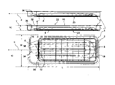
of the present invention, a heat lamp 2 of the present invention is
illustrated in Fig. Fig. la)
and Fig. lb) each show a side view, while Fig. 1c) shows a front view of one
embodiment, of
a heat lamp 2 according to the invention. The housing 4 of the heat lamp 2 is
basically box-
shaped. The housing 4 has a length L that is more than twice as long as the
width W of the
housing 4, and the thickness T of the heat lamp 2 is less than a third of the
width W of the
housing 4. Thus, the heat lamp 2 is very compact.
The heat lamp 2 has a front side 23 and a back side 22. The front side 23 of
the heat lamp 2
is open, and therefore rays, in the form of infrared electromagnetic
radiation, from the heat-
ing source 6 can radiate towards the pigs that are intended to be heated by
using the heat
lamp 2.
The heat lamp 2 has a longitudinal axis X and the heating source 6 is a U-
shaped heating el-
ement extending parallel to the longitudinal axis X of the heat lamp 2. A mesh
8 attached to
the housing 4 at the front side 23 of the housing 4. The mesh 8 shields the
heating source 6
from bedding (e.g. straw that is present in the stall).
The heat lamp 2 comprises a reflector 18 that fits the shape of the heating
source 6. The re-
flector 18 has a U-shaped groove 28 having a parabolic cross section. The U-
shaped groove
28 of the reflector 18 extends along the U-shaped heating source 6 and the
reflector 18 is
configured to reflect the rays from the heating source 6 so that the rays
reflected by the re-
flector 18 is being directed towards the pigs. The reflector 18 may be made of
any suitable
reflecting material e.g. stainless steel, such as acid proof stainless steel.
At the free end side 38 of the heating source 6 an electric member portion 36
is integrated in
the housing 4 of the heat lamp 2. The electric member portion 36 comprises a
connection
between the heating source 6 and the external electrical energy source (not
shown), such as
the mains, that the heat lamp 2 is intended to be connected to.
A light source 34 emitting visible light is integrated in the electric member
portion 36 of the
housing 4. The light source 34 is capable of attracting the pigs. The light
source 34 is used to
make the pigs come closer to the heat lamp 2.
6
CA 02848327 2014-03-11
WO 2013/044916
PCT/DK2012/000104
Moreover, the heat lamp 2 comprises a first sealing member 10 sealingly
covering the back
side 22 of the heat lamp. The heat lamp 2 further comprises a second sealing
member 10'
that is sealing the space or electrical connection between the heating source
6 and the elec-
tric member portion 36 against water. The first sealing member 10 is a casting
compound for
encapsulating and sealing the back side 22 heat lamp 2. The casting compound
may be may
be based on epoxy resins, however, any other suitable casting compound that
can provides
an efficient and reliable sealing of the heat lamp 2 may be used. It is an
advantage that the
housing 2 comprises a completely closed back side 22. The closed back side 22
ensures a
complete sealing of the back side 22 area of the heat lamp 2. Hereby, a very
reliable and en-
ergy efficient heat lamp 2 can be achieved.
Fig. 2a illustrates two perspective views of a heat lamp 2 according to the
invention. Fig. 2a)
is a perspective front view of the heat lamp 2, while Fig. 2b) shows a
perspective view of the
back side 22 of the heat lamp 2.
In Fig. 2 it can be seen, that the heat lamp 2 has a basically box-shaped
housing 4, and that
it provided with a light source 34 arranged near the free end 38 of the
heating source 6.
A mesh 8 is attached to the housing 4 at the front side 23 of the housing 4.
The mesh 8 may
be made of any suitable material e.g. stainless steel, such as acid proof
stainless steel or fi-
bre reinforced plastic. The mesh 8 shields the heating source 6, and the mesh
8 hereby pre-
vents objects from coming close to the heating source 6.
In Fig. 2b) it can be seen, that the heat lamp 2 comprises a first sealing
member 10 sealing-
ly covering the back side 22 of the heat lamp 2. The first sealing member 10
is preferable a
casting compound for encapsulating and sealing that prevents water from
entering the hous-
ing 4 from its back side 22. Accordingly, the heat lamp 2 is washable.
Fig. 3 illustrates four different views of a reflector 18 arranged in a
housing 4 according to
the invention. The reflector 18 is configured to receive a U-shaped heating
source (see Fig.
2-3). Since the reflector 18 is adapted to fit the shape of the heating source
6, it has a U-
shaped groove 28 having a parabolic cross section.
The reflector 18 is attached to the housing 4 by means of three screws 40. A
gap 24 extends
all the way between the reflector 18 and the periphery 26 of the housing 4.
The heat that is
transmitted through the reflector 18 can escape through the gab 24 so that a
part of the
heat that is "lost" through transmission of heat through the reflector may be
redirected to-
wards the pigs.
7
CA 02848327 2014-03-11
WO 2013/044916
PCT/DK2012/000104
Fig. 4 illustrates the heat distribution of a prior art heat lamp 2' and a
heat lamp 2 according
to the invention. The heat lamps 2, 2' are suspended at the same distance to a
floor. The
prior art heat lamp 2' provides a small basically circular area high
temperature area 12 sur-
rounded by a larger medium temperature area 14 that is surrounded by a low
temperature
area 16. The prior art lamp 2' provides a rather small high temperature area
12. Since the
temperature in the high temperature area 12 is intended to provide an optimum
comfort lev-
el for the pigs, the limited size of the high temperature area 12 is a
problem.
In Fig. 4b) it can be seen that the heat lamp 2 according to the present
invention provides a much larger (basically circular) high temperature area 12
than the prior
art heat lamp 2'. The high temperature area 12 is surrounded by a medium
temperature ar-
ea 14 of a smaller size and the medium temperature area 14 is surrounded by a
low temper-
ature area16.
Compared to the prior art lamp 2', the heat lamp 2 according to the invention
provides much
larger high temperature area 12 and the temperature is more homogeneously
distributed.
Accordingly, the heat lamp 2 according to the invention is configured to
provide the optimum
comfort level for the pigs.
Fig. 5 illustrates a perspective view of a housing 4 and a reflector 18
according to the inven-
tion. The reflector 18 is configured to receive a U- shaped heating source 6
like the one
shown in Fig. 1 and Fig. 2. The reflector 18 has a U-shaped groove 28 having a
parabolic
cross section. Like in Fig. 1 and Fig. 2, the U-shaped groove 28 of the
reflector 18 is intend-
ed to extend along the U-shaped heating source 6. Hereby, the reflector 18 is
can reflect the
rays from the heating source 6 so that the rays are directed towards the pigs.
Fig. 6 illustrates a perspective back side view of a housing 4 of a heat lamp
according to the
invention. A reflector 18 is integrated in the housing 4. The reflector is U-
shaped and it has a
parabolic cross section. An isolating sealing member is intended to be
provided at the back
side of the housing 4 like illustrated in Fig. 2).
All the shown embodiments of the heat lamp 2 according to the invention may be
arranged
vertically, horizontally or in any other suitable orientation.
Even though it is not indicated at any of the drawings, the heat lamp 2 may be
equipped
with means for being suspended over the box areas.
Fig. 7 shows a heating source 6 used according to the present invention. The
heating source
6 comprises a U-shaped tube. The tube is made of metal or an alloy, such as
steel, such as
stainless steel, for example acid proof stainless steel. Inside the U-shaped
tube is arranged a
heating wire 42. The heating wire 42 extends inside the tube in a helical
manner. The heat-
8
CA 02848327 2014-03-11
WO 2013/044916
PCT/DK2012/000104
ing wire is electrically isolated from the inside walls of the U-shaped tube
by being suspend-
ed in a powdered ceramic material 46, such as silicon dioxide or sand. The
heating wire 42 is
in each end electrically connected to an electric member portion 36, which in
turn is electri-
cally connected to the current bearing lead 50 of the cable 32. The electric
member portion
36 is fastened in the U-shaped tube by an electrically isolating resin 44. An
earthed lead 52
of the cable 32 is electrically connected to an earthed bridge 48, which in
turn is electrically
connected to the outer surface of the U-shaped tube. The two ends of the U-
shaped tube are
cast into a sealing member 10' of e.g. polyurethane.
Such a design of the heat lamp according to the invention makes the heat lamp
fully re-
sistant against damages caused by water, especially against damages to the
electrical ele-
ments of the lamp.
9
CA 02848327 2014-03-11
WO 2013/044916
PCT/DK2012/000104
List of reference numerals
2, 2' Heat lamp
4 Housing
6 Heat source
8 Mesh
10, 10', 10" - Sealing member
12 High temperature area
14 Medium temperature area
16 Low temperature area
X Longitudinal axis of the housing
18 Reflector
20 Electromagnetic radiation
22 Back side
23 Front side
24 Gab
26 Periphery of the housing
28 U-shaped groove
30 Box
32 Cable
34 Light source
CA 02848327 2014-03-11
WO 2013/044916
PCT/DK2012/000104
36 Electric member portion
38 Free end of the heating source
40 Fastening means
42 Heating wire
44 Heat isolation resin
46 Electrically isolating powdered ceramic material
48 Earthed bridge
50 Current bearing lead of cable
52 Earthed lead of cable
11