Note : Les descriptions sont présentées dans la langue officielle dans laquelle elles ont été soumises.
CA 02848436 2014-04-07
COOLED RF ABLATION NEEDLE
BACKGROUND
Technical Field
[0001] The present disclosure relates to advances in medical systems and
procedures for prolonging and improving human life and, more particularly, to
novel
electrosurgical instruments for tissue ablation, systems for tissue ablation
including the
electrosurgical instruments, and methods for ablating tissuescontaining
abnormalities
such as cancerous tumors using the systems for tissue Ablation.
Discussion of Related A rt
[0002] Therapeutic lesions in living bodies have been accomplished for
many
decades using radio-frequency (RF) and other forms of energy. The procedures
have
been particularly useful in the field of neurosurgery, typically where RF
ablation
electrodes (usually of elongated cylindrical geometry) are inserted into a
living body. A
typical form of such ablation electrodes incorporates an insulated sheath from
which an
exposed (uninsulated) tip extends.
[0003] Generally, the ablation electrode is coupled between a grounded RF
power
source, e.g., an electrosurgical generator, (outside the body) and a reference
ground or
indifferent electrode, e.g., return electrode, for contacting a large surface
of the body.
When an RF voltage is provided between the ablation electrode and the
reference ground,
CA 02848436 2014-04-07
RF current flows from the ablation electrode through the body. Typically, the
current
density is very high near the tip of the ablation electrode, which heats and
destroys the
adjacent tissue.
[0004] In the past, RF ablation electrodes have incorporated temperature
sensors,
for example, in the form of a thermistor or thermocouple as disclosed in U.S.
Pat. No.
4,411,266 to Cosman. Typically, the sensor is connected to a monitoring
apparatus for
indicating temperature to assist in accomplishing a desired lesion. As
generally known,
for a given tip geometry and tip temperature, lesions of a prescribed size can
be made
quite consistently, also disclosed in U.S. Pat. No. 4,411,266 to Cosman.
[0005] Over the years, a wide variety of RF electrode shapes and
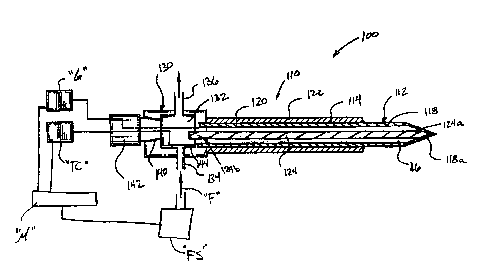
configurations
have been used, for example, several current forms are available from
Radionics, Inc.,
located in Burlington, Mass. Such electrodes have been used to accomplish
lesions in a
wide variety of targets within the body, including the brain, the spinal
column and the
heart.
[0006] An important criterion when using electrode ablation systems
relates to the
temperature of the tip achieved during the ablation process. Specifically, it
is desirable to
maintain the temperature of certain ablation electrodes, of a given tip
geometry, below
100 C. At a temperature at or above 100 C, the tissue surrounding the
ablation electrode
will tend to boil and char. Consequently, the lesion size for a given
electrode geometry
generally has been considered to be somewhat limited by the fact that the
tissue near the
tip must not exceed 100 C.
2
CA 02848436 2014-04-07
[0007] Essentially, during RP ablation, the electrode temperature is
highest near
the tip, because the current density is the highest at that location.
Accordingly,
temperature falls off as a function of distance from the electrode tip and,
except for
possible abnormalities in tissue conductivity and so on, in a somewhat
predictable and
even calculable pattern. As an attendant consequence, the size of RF lesions
for a given
electrode geometry have been somewhat limited
[0008] One proposed solution to the limitation of lesion's size has been
to employ
"off-axis" electrodes, for example the so called Zervas Hypophysectomy
Electrode or the
Gildenberg Side-Outlet electrode, as manufactured by Radionics, Inc.,
Burlington, Mass.
However, such systems, in requiring multiple tissue punctures, increase trauma
to the
patient.
[0009] Considering lesion size, it has beenseen that lesions in the brain
of up to
to 12 millimeters, by using very large ablation electrodes, may be produced.
However, in order to produce similarly sized lesions or larger sized lesions
with relatively
smaller ablation electrodes, ablations systems including ablation electrodes
with conduits
which deliver cooling fluid to the tip thereof have been developed. Reference
may be
made to U.S. Patents 5,951,546; 6,506,189; 6,530,922; and 6, 575,969,
for a detailed discussion of such systems. Generally, ablation electrodes with
cooled
conductive tips produce larger lesion volumes as compared to ablation tips
which are
not cooled.
[0010] Accordingly, a need exists for electrosurgical instruments for
tissue
ablation, systems for tissue ablation including the electrosurgical
instruments, and
3
CA 02848436 2014-04-07
method for ablating tissues containing abnormalities such as cancerous tumors
using the
systems for tissue ablation.
SUMMARY
[00111 The present disclosure relates to novel electrosurgical
instruments for
tissue ablation, systems for tissue ablation including the electrosurgical
instruments, and
methods for ablating tissues containing abnormalities such as cancerous tumors
using the
systems for tissue ablation.
[00121 According to an aspect of the present disclosure, an ablation
system is
provided. The ablation system includes an ablation electrode assembly
operatively
connectable to a source of electrosurgical energy and to a source of cooling
fluid. The
ablation electrode assembly includes a hub definine a chamber therein; at
least one
electrically conductive ablation needle extending from the hub, the ablation
needle
including a distal end portion configured to penetrate tissue, said distal end
portion being
electrically and thermally conductive for establishing electric and thermal
communication
with the tissue; a heat sink operatively connected to the ablation needle, the
heat sink
being connected to the ablation needle to draw energy away from at least the
distal end
portion thereof, the heat sink including a proximal end extending into the
chamber of the
hub; and a conduit fluidly connected to the hub for delivering fluid into the
chamber
thereof from the source of fluid, wherein the fluid withdraws energy from the
proximal
end of the heat sink.
[0013] The heat sink may be fabricated from a conductive material which is
anisotropic, such as, for example, a granite fiber.
4
CA 02848436 2014-04-07
[0014] The ablation system may further include an outlet conduit fluidly
connected to the chamber of the hub for delivering fluid from the chamber
thereof.
[0015] The ablation needle may define a cavity therein. The heat sink may
be
disposed within the cavity of the ablation needle. The cavity of the ablation
needle may
extend to the distal end portion of thereof. Accordingly, a distal end of the
heat sink may
be in conductive engagement with a distal end surface of the cavity of the
ablation
needle.
[0016] The ablation system may further include an insulative coating
surrounding
at least a portion of a length of the ablation needle. The distal end portion
of the ablation
needle may be exposed.
[00171 It is envisioned that the heat sink may encase at least a portion
of a length
of the ablation needle. Desirably, the distal end portion of the ablation
needle is exposed.
In an embodiment, an insulative coating may surround at least a portion of a
length of the
heat sink encasing the ablation needle.
[0018] The ablation system may further include a source or electrosurgical
energy
electrically connected to the ablation needle. The ablation system may still
further
include a source of cooling fluid fluidly connected to the chamber of the hub.
The
ablation system may further include a thermal-sensing circuit electrically
connected to
the ablation needle for measuring a temperature of the ablation needle. The
ablation
system may further include a microprocessor connected to and for coordinating
operation
of the source of electrosurgical energy and the source of fluid.
CA 02848436 2014-04-07
[0019] In an embodiment, it is envisioned that the ablation needle is
solid. It is
envisioned that a plurality of ablation needles may be provided.
[0020] According to a further aspect of the present disclosure, an
ablation
electrode assembly operatively connectable to a source of electrosurgical
energy and to a
source of cooling fluid is provided. The ablation electrode assembly includes
a hub
defining a chamber therein; at least one electrically conductive ablation
needle extending
from the hub, the ablation needle including a distal end portion configured to
penetrate
tissue, said distal end portion being electrically and thermally conductive
for establishing
electric and thermal communication with the tissue; a heat sink operatively
connected to
the ablation needle, the heat sink being connected to the ablation needle to
draw energy
away from at least the distal end portion thereof, the heat sink including a
proximal end
extending into the chamber of the hub; and a conduit fluidly connected to the
hub for
delivering fluid into the chamber thereof from the source of fluid, wherein
the fluid
withdraws energy from the proximal end of the heat sink.
[0021] The heat sink may be fabricated from a conductive material
including an
= anisotropic material, such as, for example, a granite fiber.
[0022] The ablation electrode assembly further includes an outlet conduit
fluidly
connected to the chamber of the hub for delivering fluid from the chamber
thereof.
[0023] The ablation needle may define a cavity therein. The heat sink may
be
disposed within the cavity of the ablation needle. The cavity of the ablation
needle may
extend to the distal end portion thereof. Accordingly, a distal end of the
heat sink may be
in conductive engagement with a distal end surface of the cavity of the
ablation needle.
6
CA 02848436 2014-04-07
[0024] The ablation electrode may further include an insulative coating
surrounding at least a portion of a length of the ablation needle. The distal
end portion of
the ablation needle desirably remains exposed.
[0025] In an embodiment, it is envisioned that the heat sink encases at
least a
portion of a length of the ablation needle. In this embodiment, desirably, the
distal end
portion of the ablation needle remains exposed. It is envisioned that an
insulative coating
may surround at least a portion of a length of the heat sink encasing the
ablation needle.
[0026] The ablation electrode assembly may further include a thermal-
sensing
circuit electrically connected to the ablation needle for measuring a
temperature of the
ablation needle.
[0027] The ablation needle may be solid. It is envisioned that a
plurality of
ablation needles may be provided.
[0028] According to yet another aspect of the present disclosure, a
method for
heat ablation of tissue in a patient is provided. The method includes the step
of providing
an ablation electrode assembly for tissue ablation. The ablation electrode
assembly
includes a hub defming a chamber therein; at least one eleotrically conductive
ablation
needle extending from the hub, the ablation needle including a distal end
portion
configured to penetrate tissue, said distal end portion being electrically and
thermally
conductive for establishing electric and thermal communication with the
tissue; a heat
sink operatively connected to the ablation needle, the heat sink being
connected to the
ablation needle to draw energy away from at least the distal end portion
thereof, the heat
sink including a proximal end extending into the chamber of the hub; and a
conduit
7
CA 02848436 2014-04-07
fluidly connected to the hub for delivering fluid into the chamber thereof
from a source of
fluid, wherein the fluid withdraws energy from the proximal end of the heat
sink.
[0029] The method further includes the steps of inserting the ablation
needle into
the tissue to a target surgical site; supplying electrical energy to the
distal end portion of
the ablation needle to effect tissue ablation proximate the distal end
portion; and cooling
=
the distal end portion of the ablation needle by circulating fluid around the
proximal end
of the heat sink extending into the chamber of the hub.-
[0030] The method mayfurther include the step of providing the heat sink
within
a cavity defined in the ablation needle.
[0031] The method may further include the step of providing an insulative
coating over a substantial length of the ablation needle to prevent ablation
of tissue in the
body of a patient contiguous to the insulative coating.
[0032] The method may still further include the step of providing at least
one of a
source or electrosurgical energy electrically connected to the ablation
needle; a source of
cooling fluid fluidly connected to the chamber of the hub; a thermal-sensing
circuit
electrically connected to the ablation needle for measuring a temperature of
the ablation
needle; and a microprocessor connected to and for coordinating operation of
the source of
electrosurgical energy and the source of fluid.
[0033] The method may further include the step of providing a
plurality of
ablation needles.
8
CA 02848436 2014-04-07
[0034] According to still another aspect of the present disclosure, an
ablation
system is provided including an ablation electrode assembly operatively
connectable to at
least one of a source of electrosurgical energy and a source of cooling fluid.
The ablation
electrode assembly includes at least one electrically conductive ablation
needle having a
distal end portion configured to penetrate tissue, wherein said distal end
portion is
electrically and thermally conductive for establishing electric and thermal
communication
with the tissue; and a heat smk operatively connected to the ablation needle,
wherein the
heat sink is connected to the ablation needle to draw energy away from at
least the distal
end portion thereof. The heat sink includes a-prokimal end extending
proximally of the
ablation needle.
[0035] The ablation electrode assembly further includes a hub defining a
chamber
therein. Accordingly, the ablation needle extends from the hub and the
proximal end of
the heat sink extends into the chamber of the hub.
[0036] The ablation system may further include a conduit fluidly
connected to the
hub for delivering fluid into the chamber thereof from the source of fluid,
wherein the
fluid withdraws energy from the proximal -end of the heat sink.
BRIEF DESCRIPTION OF THE DRAWINGS
[0037] Further features and advantages of the invention will become
readily
apparent from the following specification and from the drawings, in which:
[0038] FIG. 1 is a partial cross-sectional view of a prior art cooled
needle
electrode;
9
CA 02848436 2014-04-07
[0039] FIG. 2 is a broken-away partial cross-sectional view of the tip
part of the
cooled needle electrode of FIG. 1;
[0040] FIG. 3 is a schematic, partial cross-sectional illustiation, of an
ablation
system in accordance with an embodiment of the present disclosure;
[0041] FIG. 4 is a schematic, partial cross-sectional illustration, of an
embodiment of an ablation electrode assembly of the ablation system of FIG. 3;
[0042] FIG. 5 is a schematic, partial cross-sectional illustration, of
another
embodiment of an ablation electrode assembly of the ablation system of FIG. 3;
[0043] FIG. 6 is a schematic, partial cross-sectional illustration, of yet
another
embodiment of an ablation electrode assembly of the ablation system of FIG. 3;
[0044] FIG. 7 is a schematic, partial cross-sectional illustration, of
still another
embodiment of an ablation electrode assembly of the ablation system of FIG. 3;
[0045] FIG. 8 is a schematic perspective view of an ablation system
according to
another embodiment of the present disclosure; and
[0046] FIG. 9 is a schematic longitudinal cross-sectional view of the
ablation
system of FIG. 8.
DETAILED DESCRIPTION OF EMBODIMENTS
[0047] Referring initially to FIGS. 1 and 2, a prior art needle electrode
according
is shown and described and is generally designated as 10. As seen in FIG. 1,
needle
electrode 10 includes a distal end 16 and a proximal end 20 and further
includes an outer
CA 02848436 2014-04-07
tube 14 having a tip put 16 which is exposed and a tip point 16' (see FIG. 2)
which is
construed so as to penetrate tissue with a minimum risk of hemorrhage from the
puncture
tract. The non-exposed part of the outer tube 14 is surrounded by an
insulating material
12. A distal portion of outer tube 14 is non-insulated and thereby exposed for
DC or AC,
preferably RF delivery. An inner tube 18 is provided inside the tube 14 co-
axially with
the outer tube 14.
=
=
[0048] An adapter 40 is provided at the proximal end 20 of needle
electrode 10,
opposite the tip part or distal end 16. The-adapter 40 is equipped with a line
22, the line
22 being connected to the inner tube 18-and communicating therewith for
providing a
cooling fluid, such as water, to the distal end 16 of needle electrode 10. The
water is led
through the inner tube 18 to the tip part 16 and away from=the tip part
through the interior
of the outer tube 14. The outer tube 14 is connected to and communicates with
a line 24
for discharge of the cooling ivater. Linei 22 and 24 each communicate with a
cooling
water reservoir (not shown). Circulation of the cooling water is established
with a pump
(not shown). The outer tube 14 of the cooled needle electrode 10 is connected
to a RF
electrosurgica1 generator (not shown) through line 26 for providing power to
the cooled
needle electrode 10.
[00491 In FIG. 2, the tip part or distal end 16 of the cooled needle
electrode 10 of
FIG. 1 is shown. As seen in FIG. 2, the cooling water flows through the inner
tube 18
and out at a tip 28 of the inner tube 18 and flows into the tip part 16 and
out of the outer
tube 14 shown at 30 for thereby providing a cooled needle electrode 10.
11
=
CA 02848436 2014-04-07
[0050] Preferred embodiments of the presently disclosed
ablation system will
now be described in detail with reference to the drawing figures wherein like
reference
numerals identify similar or identical elements. As used herein, the term
"distal" refers to
that portion which is further from the user while the term "proximal" refers
to that
portion which is closer to the user.
[0051] Referring now to FIGS. 3 and 4, an ablation system,
in accordance with an
embodiment of the present disclosure, is shown generally as 100. Ablation
system 100
includes an ablation electrode assembly 110 operatively connected to an
electrosurgical
energy source "G" (e.g., an electrosuitical generator), and a source of
cooling fluid "FS".
A microprocessor or computer "M" may be connected to energy source "G" and
fluid
= source "FS" for controlling and monitoring the operating parameters of
ablation system
100.
[0052] As seen in FIGS. 3 and 4, ablation electrode assembly
110 includes an
elongate ablation needle 112 which is configured and dimensioned for insertion
into a
= patient, either percutaneously or intraoperatively. Ablation needle 112
includes a
substantially cylindrical body or shaft portion 114 defining a cavity or
chamber 116
therein. Ablation needle 112 includes a distal end portion 118 having a
sharpened tip
118a, and a proximPl end portion 120 configured and adapted for connection to
a hub 130
or the like. Desirably, ablation needle 112 is fabricated from electrically
conductive
material, such as, for example, stainless steel, titanium, etc.
= [00531 Ablation electrode assembly 110 has an insulative coaling
122 over at
least a portion of the length of ablation needle 112, preferably, over most of
the length of
12
CA 02848436 2014-04-07
ablation needle 112. Desirably, insulative coating 122 extends from hub 130 to
distal end
portion 118 of ablation needle 112, such that distal end portion 118 of
ablation needle
112 is exposed or un-insulated. Insulative coating 122 selectively prevents
the flow of
electrical current from shaft portion 114 of ablation needle 112 into
surrounding tissue.
Thus, insulative coating 122 shields the intervening tissue from RF current,
so that such
tissue is not substantially heated along the length of shaft portion 114
except by the
heating effect from distal end portion 118 which is exposed.
[0054] Ablation electrode assembly 110-further includes at
least one heat sink, in
the form. of heat strap or heat pipe 124 extending through cavity 116 of
ablation needle
112. While a single heat strap 124 is shown and will be described, it is
envisioned and
within the scope of the present disclosure-for a plurality of heat straps 124
to be provided.
Heat strap 124 includes a distal end 124a operatively secured to ablation
needle 112 and a
proximal end 124b extending into a cavity 132 formed in hub 130. In the
present
= embodiment, distal end 124a of heat strap 124 is operatively connected or
secured to
distal end portion 118 of ablation needle 112. In an embodiment, distal end
124a of heat
strap 124 is bonded to distal end portion 118 of ablation needle 112 with a
thermally
conductive adhesive or the like.
[0055] Heat strap 124 is fabricated from a highly heat
conductive anisotropic
material, such as, for example, graphite fiber. Accordingly, in use, as will
be described in
greater detail below, heat strap 124 draws heat away from distal end portion
118 of
ablation needle 112 and dissipates the heat along a length thereof. In order
to increase
the efficiency and the rate of heat dissipation, as will be described in
greater detail below,
a cooling fluid may be circulated over proximal end 124b of heat strap 124.
13
CA 02848436 2014-04-07
[00561 As seen in FIG. 3, ablation system 100 further includes a hub 130
configured and adapted to support ablation electrode assembly 110. Hub 130
defines a
chamber 132 therein, an inlet conduit 134 for delivering cooling fluid "F"
into chamber
132 from fluid source "FS", and an outlet conduit 136 for delivering cooling
fluid "F"
from chamber 132. In operation, cooling fluid "F" is commnnicated into chamber
132
through inlet conduit 134 and out of chamber 132 through outlet conduit 136.
[0057] As.mentioned above, with-proximal end 124b of heat strap 124
extending
into chamber 132 of hub 130, as coolitig.fluid--"F" is circulated through
chamber 132 of
hub 130, heat or energy is withdrawn from proximal end 124b of heat strap 124
and
carried away to fluid source "FS". for re-cooling and the like.
[0058] As seen in FIG. 3, hub 130 may include a proximal connector known
as a
luer connector, which is a tapered hole 140 or the like. Into female luer
connector 140, a
hub of a high frequency or therrao-sensing electrode 142 may be inserted and
sealed by
its male luer connection. A probe 144 of thermo-sensing electrode 142 may be
connected
to ablation needle 112 which can sense. the. temperature of ablation needle
112 at that
point, or alternatively, may sense the temperature of distal end portion 118.
Since distal
end portion 118 of ablation needle 112 is contiguous and in contact on its
external surface
with the target tissue within the patient's body, thermo-sensing probe 144
can, depending
on the thermal contact with ablation needle 112, get a measure of the
temperature of the
tissue immediately outside of distal end portion 118.
[0059] Connected to or within the hub of the high frequency and/or themio-
sensing electrode 142 are connections indicated by the dashed lines which
connect to a
14
CA 02848436 2014-04-07
high frequency electrosurgical generator "G" and/or a thermal-sensing circuit
"TC" that
may be outside of the body.
[00601 Electrosurgical generator "G" may be the source of high
frequency voltage
which produces the high freauency current that emanates from the distal end
portion 118
of ablation needle 112. The thermal-sensmg circuit "TC" may be of a
thermocouple type
and the temperature sensor could also be a bi-metal junction thermocouple such
as a
copper constantan.
[0061] Turning now to FIG. 5, an alternate embodiment of
ablation electrode
assembly is generally shown as I 10a. Ablation electrode assembly 110a is
substantially
similar to ablation electrode assembly 110 and thus will only be discussed in
detail to the
extent necessary to identify differences in construction and/or operation. As
seen in FIG.
5, heat strap 124 completely fills cavity 116 of ablation needle 112. In so
doing,
= dissipation of heat and/or energy may take place along substantially the
entire length of
ablation needle 112.
[0062] As mentioned above with regard to ablation electrode
assembly 110, with
regard to ablation electrode assembly 110a, with proximal end 124b of heat
strap 124
= extending into chamber 132 of hub 130, as cooling fluid "F" is circulated
through
chamber 132 of hub 130, heat or energy is withdrawn from proximal end 124b of
heat
strap 124 and carried away to fluid source "FS" for re-cooling and the hire.
It is
contemplated that proximal end 124b of heat strap 124 may include a plurality
of fingers
125 or the like, thereby increasing the surface area over which fluid "F" is
circulated and
thus increasing the rate of heat and/or energy dissipation.
CA 02848436 2014-04-07
[0063] Turning now to FIGS. 6 and 7, alternate embodiments of ablation
electrode assemblies are generally shown as 110b and 110c, respectively.
Ablation
electrode assemblies 110b, 110e are substantially similar to ablation
electrode assembly
110 and thus will only be discussed in detail to the extent necessary to
identify
differences in construction and/or operation.
[0064] As seen in FIG. 6, ablation electrode assembly 110b includes a
heat sink
or heat strap, in the form of a sleeve or coating 224 wrapped around or
surrounding at
least a portion of the length of ablation needle 112, preferably over most of
the length of
ablation needle 112. Desirably, heat strap 224 extends to and not beyond
distal end
portion 118 of ablation needle 112, thus maintaining distal end portion 118 of
ablation
needle 112 exposed. Heat strap 224 includes a proximal end portion 224b which
extends
through hub 130 and into cavity 132.
[0065] In this embodiment, insulating coating 122 desirably encases and/or
surrounds substantially all of heat strap 224. Alternatively, heat strap 224
may function
as an insulating sleeve or bather, thus eliminating the need for an insulating
coating 122
disposed on or about heat strap 224.
[0066] As seen in FIG. 7, ablation electrode assembly 110c may include an
ablation needle 112 which is solid (i.e., no cavity 116 is provided). In the
present
embodiment, heat strap 224 substantially encases ablation needle 112.
Desirably, distal
end portion 118 of ablation needle 112 remains exposed. Heat strap 224
includes a
proximal end portion 224b which extends through hub 130 and into cavity 132.
As with
16
CA 02848436 2014-04-07
=
the embodiment in FIG. 6, heat strap 224 of the present embodiment also
functions as an
insulating coating or the like.
[0067] Desirably, distal end portion 118 of ablation needle
112 is exposed about
2.0 cm in length. Ablation needle 112 desirably has a transverse diameter of
about 2 mm.
[0068] In operation, ablation electrode assembly 110 is
inserted into an operative
site of a patient, either percutaneousiv or mtra-operatively. Desirably,
ablation electrode
assembly 110 is inserted into the operative site until distal end portion 118
of ablation
needle 112 is positioned or disposed adjacent to or within a target tissue to
be ablated. A
return pad or return electrode (not shown) may know be or may previously have
been
operatively adhered to or connected to the patient Any known technique may be
used to
visually position distal end portion 118 of ablation needle 112 in the
operative site, such
as, for example and not limited to, X-ray imaging, CT scanning, Mm's,
fluoroscopy,
angiographic, PET, SPECT,:MEG; ultrasonic imaging, etc.
[0069] With distal end portion 118 of ablation needle 112 in
position,
= electrosurgical energy is delivered from electrosurgical generator "G" to
distal end
portion 118 of ablation needle 112. Desirably, an effective amount of
electrosurgical
energy at an: effective energy revel and for an effective duration of time is
delivered to
distal end portion 118 of ablation needle 112 to treat and/or ablate the
target tissue of the
like. For example, electrosurgical generator "G" may deliver an energy
frequency of
from about 100 kilo Hertz to several hundred mega Hertz. An example of an
electrosurgical generator "G" capable of producing such an output is the
lesion generator
available from Radionics, Inc, of Burlington, Mass.
17
CA 02848436 2014-04-07
[0070] Either prior to or simultaneously with the delivery of
electrosurgical
energy to distal end portion 118 of ablation needle 112, a fluid "F" (e.g.,
water, saline,
etc.) is circulated through chamber 132 of hub 130. Desirably, fluid "F" is
cooled to a
temperature of about 0 C prior to circulation. During circulation, fluid "F"
enters
chamber 132 of hub 130 through inlet conduit 134 and exits chamber 132 of hub
130
through outlet conduit 136. In so doing, fluid "F" contacts and/or washes
over/across
proximal end 124b or 224b of heat straps 124, 224, respectively, and withdraws
heat
and/or energy therefrom and, in turn, from ablation needle 112.
[0071] Following treatment or ablation of the target tissue, ablation
electrode
assembly 110 may be withdrawn from the target site and re-introduced into
another target
site, into the same target site from a different angle or approach, or in
substantially the
same location.
[0072] Turning now to FIGS. 8 and 9, ablation system 100 may include a
cluster
"C" or plurality of ablation electrode assemblies 110 supported in hub 130.
Desirably,
any of ablation electrode assemblies 110-110c may be supported on or
operatively
connected to hub 130. Cluster "C" of ablation electrode assemblies 110 are
each
connected to electrosurgical generator "G". Accordingly, cluster "C" will
effectively act
as a larger electrode.
[0073] It is envisioned that ablation electrode assemblies 110 may be
arranged in
a substantially linear array, as shown in FIG. 9, or may be evenly spaced from
one
another, as shown in FIG. 8. While three ablation electrode assemblies 110 are
shown
18
CA 02848436 2014-04-07
and described, it is envisioned that any number of ablation electrode
assemblies may be
provided.
[00741 In use, as fluid "F" is circulated through chamber 132 of hub 130,
fluid
"F" circulates over or washes across proximal ends 224b of heat straps 224 of
each
ablation electrode assembly 110 extending into chamber 132 of hub 130. In so
doing,
heat and/or energy is/are drawn from each heat strap 224 and, in turn, from
each ablation
needle 112.
[0075] The use of a multiplicity of N ablation electrode assemblies 110
increases
the overall conductive exposed tip area by which to send RF current for
heating into the
target tissue site. This increases the heating power that may be delivered and
thus
increases the size of the ablation volume possible.
[00761 The cooling capacity of a multiplicity of N ablation electrode
assemblies
also increases as the number N increases. Increasing the number of ablation
electrode
assemblies increases the cooling surface area near cluster "C". Thus, the heat
sinking
effect from a cluster of ablation electrode assemblies is greater than the
heat sinking
effect from a single ablation electrode assembly. This allows the size of a
lesion to be
expanded accordingly.
[0077] For example, in specific embodiments, ablation electrode assemblies
110
of cluster "C" may have diameters in the range of about 0.5 mm to about 3.0
mm. An
advantage of a multiplicity of coherent smaller electrodes versus insertion of
a single
large electrode is that the smaller electrodes will produce less chance of
hemorrhage.
19
CA 02848436 2014-04-07
[0078] Although the
subject device, systems and methods have been described
with respect to preferred embodiments, it will be readily apparent, to those
having
ordinary kill in the art to which it appertains, that changes and
modifications may be
made thereto without departing from the spirit or scope of the subject of the
present
disclosure.