Note : Les descriptions sont présentées dans la langue officielle dans laquelle elles ont été soumises.
CA 02848527 2014-03-12
WO 2013/024299 PCT/GB2012/052005
1
Railway Track Support System
The present invention relates to a method of supporting or stabilizing railway
track
and, more particularly, a system for stabilizing existing track, for example
to
remedy or control ground settlement problems.
Railway track conventionally comprises a pair of spaced rails laid on sleepers
which support the passage of a railway vehicle over the rails. The sleepers
are
typically laid laterally relative to the rails and supported on ballast, such
as crushed
stone or similar.
Whilst the combination of subgrade layer materials, ballast and sleepers is
generally sufficient to dissipate the compression force of a railway vehicle
passing
there-over, it is an acknowledged problem that the nature or make-up of the
underlying soil can adversely affect the stability and/or longevity of the
track. For
example, if the underlying soil comprises a so-called 'wet bed', for example
which
may contain a proportion of peat, it is possible that the ground beneath the
track
can contract and thereby cause sagging or sinking of the track.
The above scenario represents one specific example, by which the underlying
soil
can cause deterioration of the track geometry, and it will be appreciated by
the
skilled person that other examples exist in which the subgrade, typically
comprising a fine-grained, clay-like or silt-like soil, beneath a railway
track may be
insufficient to support the passage of railway vehicles over time due to soil
settlement, compression or other phenomena. Such effects may be attributed to,
for example, moisture-density-strength relationships and/or corresponding soil
properties such as bearing capacity or compressibility.
The deterioration of the track by a relatively small degree can lead to speed
restrictions being put in place. In more pronounced conditions, the track
deterioration can lead to serious safety risks.
CA 02848527 2014-03-12
WO 2013/024299 PCT/GB2012/052005
2
The problems described above are of greater prevalence with increasing speed
capabilities of trains. In particular, an increase in the speed of rail
vehicles can
lead to faster deterioration of the track. Even in relatively minor cases of
track
dislocation, significant investments made in providing improved trains which
are
capable of greater speeds can be negated by the need to impose speed
restrictions over portions of the rail network.
Conventional methods of restabilising the track have required complete removal
or
overhaul of the existing track, including re-laying of ballast and re-aligning
the
track on the ballast. Some conventional methods include the addition of an
adhesive material to the ballast in the hope of preventing future
deterioration. Such
processes are costly and time consuming and can result in significant downtime
of
the track, which can cause further associated cost and disruption to railway
vehicle
operators. Furthermore, even if attempts are made to treat shallow subgrade or
improve the performance of the ballast layer, the replacement of the track may
then be subjected to further movement of the ground or soil beneath, such that
further restabilising of the track may be required in the future.
It is an aim of the present invention to provide a method of stabilising
existing
railway track which mitigates at least some of the above problems. It may be
considered an alternative or additional aim of the invention to provide a
system for
stabilising existing railway track in situ.
According to the present invention there is provided a method of stabilising
railway
track comprising: inserting a hollow elongate support into the ground in the
vicinity
of the railway track, the support being inserted to a depth such that the
entire
support is below the surface of the ground thereby leaving a void between the
support and the surface of the ground; inserting a first cementitious material
into
the hollow interior of the support; and, inserting a second aggregate material
into
the void between the support and the ground surface.
The method may advantageously be performed in situ for an existing railway
track.
Accordingly, the ground surface may constitute the level of an existing
ballast
CA 02848527 2014-03-12
WO 2013/024299 PCT/GB2012/052005
3
layer, to which the second aggregate material may be augmented. The method
may be repeated or duplicated along a length of the railway track. Any, or any
combination of, the method steps may be repeated concurrently or sequentially
at
different locations along the length of the track.
The cementitious material is typically inserted into the support in situ.
The present invention is widely applicable to existing railway track, which
carries
the advantage that the method can be carried out in areas, such as for
example,
the approach to train stations, where it is impractical to perform
conventional track
restabilising methods that require reballasting. Furthermore, restabilisation
of a
length of track can be carried out in stages (i.e. inserting one or a small
number of
supports at a time) without disruption to track use between those stages.
In one embodiment, the ground may comprise a region of relatively soft or wet
subgrade and the method comprises inserting the support into said region. The
support may be inserted such that it extends through said subgrade region. The
support may be of a length which is of an order of magnitude similar to the
depth
of the subgrade region.
In one embodiment the method may be performed in a region in which the ground
beneath the subgrade is typically harder than the softer subgrade region.
Accordingly the support may allow for the communication of load from the
ground
surface to the harder region beneath the subgrade. That is to say the support
may
allow the load on the softer subgrade to be reduced during passage of rail
vehicles
there-over or else may allow the soft subgrade to be at least partially
bypassed or
short-circuited in a load bearing capacity.
According to a preferred embodiment, the support is inserted into the ground
at a
location inbetween adjacent sleepers of the railway track. Two supports may be
inserted at spaced locations in the space between adjacent sleepers. The two
supports may be spaced laterally with respect to the direction of the track.
One or
more supports may be inserted into the ground between successive pairs of
CA 02848527 2014-03-12
WO 2013/024299 PCT/GB2012/052005
4
adjacent sleepers along a length of track to be supported. The supports may be
inserted between successive pairs of sleepers in a regular repeating pattern
along
the length of track to be supported. For example, supports may be inserted
between alternate pairs of sleepers.
The, or each support, may be inserted into the ground at a location between
the
opposing rails of the railway track. Additionally or alternatively, one or
more
supports may be inserted into the ground immediately outside of, or adjacent
to,
the rails, but, typically, between adjacent sleepers.
The support may comprise a generally tubular body which may be closed at one
end.
The support may have a first or leading end, which is to be inserted into the
ground to a greater depth than a second or trailing end. The first end may be
closed. The second end is typically open or else has an opening therein to
allow
insertion of the cementitious material into the hollow interior of the
support.
The second or trailing end may comprise a head of flange formation. The
formation may have a greater width or diameter dimension than the remainder of
the support. The formation may comprise a circumferential end wall. The
formation
may be attached to the support during the method of the invention. For
example,
the support may be driven into the ground to a first depth such that the
second end
is above the ground surface, at which point the formation may be attached to
the
support before driving the support deeper into the ground. A driving force may
be
applied to the support via the formation, for example via a correspondingly
shaped
or dimensioned driving tube.
The support may be a pile.
One or more openings may be provided in the support. The support may be
overfilled with cementitious material such that it passes through the one or
more
openings into the ground. One or more openings may be provided in a wall (e.g.
CA 02848527 2014-03-12
WO 2013/024299 PCT/GB2012/052005
side wall) of the support. In use, a portion of the cementitious material
inserted into
the support may seep through the one or more openings. This leaked portion of
cementitious material may enter or penetrate the surrounding subgrade or
substrata and thereby enhance the stabilisation thereof.
5
The support may be between 2m and 8m in length, typically between 2.5 and 7
metres or 3 and 6 metres.
The aggregate material may comprise a coarse aggregate. The aggregate
material may comprise ballast. The aggregate may be loose. The average grain
size of the aggregate is typically significantly larger than that of the
cementitious
material.
According to one embodiment, the support may be overfilled with cementitious
material such that a volume of cementitious material lies above the uppermost
end
of the support within the void. This may form a cementitious cap on the
support.
When the aggregate material is inserted into the void, it may advantageously
enter
into the cementitious material in the void so as to form a region in which
both the
aggregate and cementitious material are present. Such an intermediate region
may be located in a lower region of the void, that is between the support and
the
uppermost ballast region once complete.
The cementitious material may be poured into the support using a pipe, such as
a
so-called Tremie pipe.
The void may be filled with the aggregate material via a hollow or tubular
member.
The aggregate may be allowed to fill the void during retraction of the hollow
member. The void may be back-filled with aggregate. A driving tube may be used
to drive the support into the ground. The aggregate material may be inserted
into
the void via the hollow driving tube.
According to a further aspect of the invention there is provided a railway
track
support system, comprising a plurality of supports submerged in a generally
CA 02848527 2014-03-12
WO 2013/024299 PCT/GB2012/052005
6
upright orientation below ground level in the vicinity of the railway track,
each
support having a solidified cementitious material therein and wherein the
region
between an uppermost end of the support and the ground level on which the
railway track is located is substantially filled with aggregate.
Any of the optional features defined in relation to the structure formed by
the
method of the first aspect, or else the components or materials used in said
method, may also apply to the system of the second aspect.
The terms "railway" and "sleepers" in UK English, as used herein, may be
considered interchangeable with the terms "railroad" and "ties", as used, for
example, in American English.
Practicable embodiments of the invention are described in further detail below
with
reference to the accompanying drawings, of which;
Figure 1 shows a side view of a section of conventional railway track to be
stabilized in accordance with the present invention;
Figure 2 shows a section view through a support and associated railway track
during stabilisation according to one embodiment of the invention;
Figure 3 shows an above view of a plurality of the supports shown in Figure 2
located relative to the railway track;
Figure 4 shows a section view of a railway track support system according to
one
embodiment of the invention; and,
Figure 5 shows a plan view of a section of railway track including the
location of
the supports for stabilisation of the track according to a further embodiment
of the
invention.
CA 02848527 2014-03-12
WO 2013/024299 PCT/GB2012/052005
7
The present invention derives from the basic concept that it is possible to
adequately stabilise a section of railway track at the onset of track
deterioration
due to poor subgrade support by piling in the vicinity of the railway track.
This can
be achieved for example in the window of opportunity when the deterioration of
the
track has been detected but whilst the track is still safe to use. Such a
window of
opportunity may occur, for example, when a speed restriction is placed on a
section of track to avoid further track degradation.
Turning firstly to Figures 1 and 3, there are shown portions of conventional
railway
track 10 comprising a pair of spaced rails 12 supported by laterally arranged
sleepers 14 which hold the rails at the desired spacing or gauge. Resilient
fasteners 16, or variants thereof, are used to attach a rail 12 to each
sleeper 14.
Typically two fasteners per rail per sleeper are provided, one on each side of
the
rail, as can be seen in Figure 3. The rails, sleepers and fasteners are all of
conventional design and materials and need not be altered to accommodate the
present invention.
The sleepers 14 are laid upon, and supported by, a bed of ballast 18. The
depth
and makeup of the ballast may vary from location to location but typically
comprises fragmented, crushed or otherwise coarse stone or gravel. A
conventional track arrangement comprises both ballast and sub-ballast layers,
with
the former, upper ballast layer comprising generally larger pieces, whilst the
sub-
ballast layer typically comprises a particulate material of smaller grain size
which
supports the upper ballast layer.
The process carried out according to one embodiment of the invention is
described below with reference to the conventional track structure of Figure
1.
Firstly a volume of ballast 18 is removed from between adjacent sleepers 14. A
pile 20, typically formed of steel or another conventional pile material, is
oriented
vertically above the space between the adjacent sleepers 14 and the rails 12
as
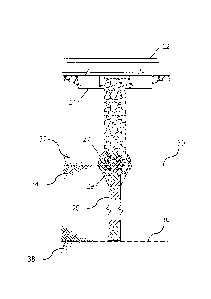
shown in Figure 1. The pile 20 is generally tubular in shape and has a closed
end
21 and an opposing open end 22. A pile of diameter of between 100 and 250 mm,
CA 02848527 2014-03-12
WO 2013/024299 PCT/GB2012/052005
8
or, more specifically between 120 and 160 mm may be suitable. In the present
embodiment a pile of 140 mm was selected.
In alternative embodiments, the pile may have an open end and may be provided
with a reinforcing or cutting member, such as a so-called cutting shoe, which
may
take the form of a collar member arranged for attachment about an open end of
the pile.
The pile length may be any acceptable length for the given pile diameter and
strength requirements in use and may be between, for example, 2m and 8 m in
length depending on the subgrade at the installation location. In the present
example a pile length between 3 and 6 m was used. However other instances of
use of the invention will typically involve geotechnical study and/or
structural
design calculations to determine a suitable length of pile or depth of
insertion,
which may be outside of the above suggested range.
The pile 20 is driven into the ground between the sleepers 14 in a generally
vertical direction using conventional piling machinery such that the closed
end 21
enters the ground first. However in location in which the track is curved in
plan
and/or banked or otherwise angled relative to horizontal, the pile may be
inserted
into the ground at an angle to accommodate such features. The angle of
insertion
may be substantially perpendicular to the angle of the sleepers, or obliquely
angled relative thereto as necessary. The pile is driven into the ground
initially to a
depth such that a portion of the pile, towards the upper end 22 remains
exposed
above the ground. At this point a flange member 24 is attached, in situ, to
the open
end 22 of the pile.
The flange member 24 is shown in Figure 4 and comprises a generally disk
shaped member having a central opening 25 therein. The opening 25 is
substantially aligned with the longitudinal axis of the pile such that the
flange
member 24 rests against the open end of the pile. The flange member 24 may
have one or more locating formations which are arranged for insertion into the
end
of the pile to facilitate correct location and subsequent fixing of the flange
member
CA 02848527 2014-03-12
WO 2013/024299 PCT/GB2012/052005
9
to the pile. Once the flange member 24 is rigidly fixed in this manner it
provides a
head formation at the pile end 22.
The pile 20 is driven further into the ground using a driving tube 26 as shown
in
Figure 2. A driving force is applied to the pile 20 via the tube 26. The tube
26 may
also be vibrated in order to further assist in the piling process,
particularly as the
pile passes through the ballast. The pile may subsequently be pushed as it
progresses through the subgrade material.
The driving tube is of diameter greater than that of the pile 20 but less than
or
equal to the outer diameter of the head formation 24. This causes the
formation of
a void 28 above the pile 20 as it is inserted into the ground. The void 28 is
of a
width diameter that is greater than that of the pile 20 and typically
substantially
equal to the width/diameter of the tube 26 and/or flange 24.
The pile pierces the subgrade material and is driven until the end 22 achieves
a
predetermined depth below the ground surface. The predetermined depth, shown
as dimension "Y" in Figure 2 may be, for example, 1 m. Additionally or
alternatively, the predetermined depth may be such that the open (upper) end
22
of the pile, and the associated flange 24 is approximately at the lowermost
level of
the ballast or sub-ballast layer. Additionally or alternatively, the pile may
be driven
such that its lowermost (closed) end 21 comes into contact with bedrock or a
further material layer beneath the subgrade material. It will be appreciated
that the
exact depth will vary from location to location depending on the ground
conditions
and the length of pile used. However the upper pile end will typically achieve
a
depth of between 0.5 and 3 m below ground level.
The depth to which the pile is driven can be determined based upon the length
of
the driving tube that is above ground level. Typically the driving tube is
sufficiently
long that at least a portion thereof is exposed above ground level when the
pile
reaches its final resting position/depth.
CA 02848527 2014-03-12
WO 2013/024299 PCT/GB2012/052005
The larger width of the flange 24 relative to the pile body is advantageous
since it
drags finer, typically particulate, ballast material with it during insertion
of the pile.
This is depicted in Figure 2 at 29. This "wedge" of ballast material can
assist in
stabilising the pile within the subgrade and can also serve to promote load
5 transmission to the pile via the ballast once the railway track is back
in service.
The final resting position of the pile is shown in Figures 2 and 4. Here it
can be
seen that the open end 22 of the pile lies generally in the region of the
interface 30
between the existing ballast (or sub-ballast) 32 and the subgrade 34. Also the
10 lower, closed, end 21 of pile 20 lies approximately in the region of the
interface 36
between the subgrade 34 and a further material 38, such as bedrock, or a
deeper
subgrade material layer, which is typically harder/stronger than the subgrade
34.
The subgrade material 34, through which the pile is inserted may constitue a
subsoil or substrata layer.
The pile is then filled with a concrete or grout material via the open end 22.
This is
achieved by first retracting/raising the driving tube a small distance, such
as
approximately 100-300 mm, above the flange 24. A Tremie pipe is inserted down
the hollow driving tube 26 and the grout is poured into the pile 20 through
the
opening 25 in the flange.
A water-cement ratio of approximately 0.45 is used, although an alternative
ratio
generally in the range 0.4-0.5 may be suitable.
The pile is overfilled with grout. That is to say grout is poured until the
level of
grout is above the level of the flange 24 such that the grout fills, or at
least partially
fills, the space left between the end of the driving tube and the flange. In
this
embodiment the grout is filled to the level of the lower end of the driving
tube. This
overfilling with grout provides an "end cap" 27 comprising cementitious
material
immediately above the pile head. Also, since the retraction of the driving
tube 26
may cause partial collapse in the ballast material about the void 28, the end
cap
region will typically comprise a mix of ballast and grout. This intermediate
region is
CA 02848527 2014-03-12
WO 2013/024299 PCT/GB2012/052005
11
advantageous in transferring load from the ballast to the pile 20 once set
(i.e.
when the railway track is in service).
The grout may also, at least partially, penetrate the wedge 29, further
stabilising
the pile.
As part of the filling process, the grout is typically poured to the desired
level and
then allowed to settle/stabilise for a short time period, such as one or a few
minutes. The grout level may then be topped up if it falls in this timeframe.
The void 28 is then filled with ballast. This is achieved by backfilling, such
that the
void is filled by pouring of ballast material through the tube, whilst the
tube is being
retracted. Depending on the makeup of the existing ballast, a finer, sub-
ballast
material may be inserted first followed by a coarser ballast material to mimic
the
surrounding ballast structure. The filler material may thus comprise a ballast
and
granular mix.
The ballast filler material can in general be distinguished from the grout
material in
that the ballast is generally loose/dry and of grain size being typically an
order of
magnitude or more larger than that of the wet grout material.
Once the tube 26 has been retraced, the ballast 18 between the sleepers 14 can
be filled to the desired level, either with the existing (previously removed),
or else
fresh, ballast.
The grout then sets forming a strong support for the railway track through the
problematic subgrade material 34. Also it can be seen that the resultant end
cap
region 27 is formed substantially at the interface 30 between the existing
ballast
and the subgrade 34 layers.
In Figure 2, there is shown the locations of piles relative to the existing
rails 12 and
sleepers 14. The piles are inserted in pairs, each pile in the pair being
spaced from
the other by the longitudinal axis 40 of the track. In particular the piles
are
CA 02848527 2014-03-12
WO 2013/024299 PCT/GB2012/052005
12
symmetrically located on either side of the axis 40. Each pile may be
laterally
spaced from the axis such that each pile is closer to a rail 12 than to the
axis 40.
The centre of each pile may be spaced from the corresponding rail by
approximately 250-300 mm, typically around 275 mm.
Each pile is preferably located equidistantly between adjacent sleepers 24.
Piles are inserted between every other pair of adjacent sleepers 14. However
in
particularly problematic areas it is possible that piles could be inserted
between
every pair of sleepers. Conversely, piles may be inserted between pairs of
sleepers less frequently in lesser problematic areas. A repeating pattern of
"piled"
and "un-piled" pairs of sleepers may be created along the length of the track.
Further repeating patterns of piles may be used, for example in which pairs of
piles
arranged as described above are spaced by a single intermediate pile.
Turning now to Figure 5, there is shown a sequence in which piles may be
inserted. The piles 20 are numbered 1 to 8 to show the order in which they are
inserted into the ground. In this manner a longitudinal row (with respect to
the
track axis 40) of piles 20 are inserted prior to insertion of the adjacent row
of piles.
Each pile may be installed and filled before inserting the next pile in the
sequence.
Typically the backfilling with ballast will also be carried out prior to
moving on to
the next pile. However different sequences and orders of insertion are
possible
dependent on the available machinery in the interests of achieving
installation
efficiency provided it does not cause detriment to the support system.
Figure 4 shows a schematic section through the pile and surrounding ground
after
the support system has been installed. In use, as a railway vehicle passes
over
the track 12 above the pile and the temporary applied load is communicated via
the sleepers and ballast through the end cap region 27 and the pile itself 20
to the
firmer ground 38 beneath. The support system therefore serves to reduce the
load
applied to the subgrade in use and thus avoid any deterioration or further
deterioration of the subgrade.
CA 02848527 2014-03-12
WO 2013/024299 PCT/GB2012/052005
13
Subgrade deformation has been found to be the primary factor in causing
geometry deterioration of existing track and so the present invention
effectively
mitigates against this problem at its root cause and in a manner which does
not
cause significant disruption to the track. The locating of the piles between
the
sleepers is considered to be particularly beneficial in supporting the load of
a
railway vehicle passing there-over. However it is possible in other
embodiments
that piling may be undertaken at locations adjacent to rather than between the
track and/or sleepers. In any embodiment, the support structure left in place
by the
above described installation process improves the track modulus and/or track
stiffness.
Whilst the above-described implementations of the invention refer to the use
of a
hollow tubular pile, it will be appreciated that other hollow support profiles
may be
used which leave at least a partial void behind the leading end of the support
upon
insertion into the ground. Other hollow supports may include for example box-
section piles. Alternatively, piles which are open sided in section but which
define
a partially enclosed interior space, such as l-section (for example, so-called
Universal Beam or Universal Column), H-section or C-section (channel) piles
may
be used to similar effect. As with the closed end of the tubular pile, such
alternative pile shapes may have an end formation or plate for dislodging the
subsoil upon insertion so as to leave a void along the length of the inserted
pile,
which can be subsequently filled with grout. Such an interior or internal void
will be
bounded by the wall(s) of the pile.
All such variants of the invention will typically be of an extruded
construction, such
the section profile is substantially constant along the length of the pile,
save for
any end formations. Also, all such variants will bound or at least partially
bound an
internal space between opposing wall portions of the pile.
In a further development of the invention, the pile may be provided with
openings
through one or more walls thereof, such as sidewalls, web or flange walls.
Thus
when grout is poured into the pile, a volume of grout will flow through the
holes
and into the surrounding substrata. That grout will penetrate the substrata to
a
CA 02848527 2014-03-12
WO 2013/024299 PCT/GB2012/052005
14
degree and thereby serve to stabilise the soil immediately surrounding the
pile.
This may also serve to improve keying between the pile and the subgrade. The
openings in the pile will typically open in a substantially lateral direction
relative to
the longitudinal axis of the pile. The openings are dimensioned to allow
leakage of
only a fraction of the grout, such as 20% percent or less therethrough. When
filling
a pile having such openings, the pile will typically be initially overfilled,
followed by
a wait of extended duration to allow passage of the grout through said
openings
into the surrounding subsoil, prior to topping up of the grout to the desired
level.