Note : Les descriptions sont présentées dans la langue officielle dans laquelle elles ont été soumises.
84139385
1
SUBINTIMAL RE-ENTRY CATHETER AND RETROGRADE RECANALIZATION
CROSS-REFERENCE TO RELATED APPLICATIONS
This application claims priority to U.S. Provisional Application No.
61/536,229, filed
on September 19, 2011.
TECHNICAL FIELD
The disclosure is directed to devices and methods for recanalization of an
occluded blood vessel. More particularly, the disclosure is directed to
devices and methods
for re-entry into the true lumen from the extraluminal or subintimal space of
a blood vessel.
BACKGROUND
Chronic total occlusion (CTO) is an arterial vessel blockage that obstructs
blood
flow through the vessel, and can occur in both coronary and peripheral
arteries. In some
instances, it may be difficult or impossible to pass through the CTO with a
medical device in
an antegrade direction to recanalize the vessel. Accordingly, techniques have
been developed
for creating a subintimal pathway (i.e., a pathway between the intimal and
adventitial tissue
layers of the vessel) around the occlusion and then re-entering the true lumen
of the vessel
distal of the occlusion in an attempt to recanalize the vessel. In some
instances re-entering the
true lumen from the subintimal space and/or recanalization can be difficult.
Accordingly, it is
desirable to provide alternative recanalization devices and/or methods of
recanalizing a blood
vessel in which a CTO is present.
SUMMARY
The disclosure is directed to several alternative designs, materials and
methods of
manufacturing medical device structures and assemblies, and uses thereof.
Accordingly, one illustrative embodiment is a catheter for recanalizing a
blood vessel
having an occlusion therein. The catheter includes a catheter shaft having a
proximal end, a
distal end, and a distal end portion proximate the distal end. The catheter
also includes an
expandable member coupled to the distal end portion of the catheter shaft. A
flexible tubular
CA 2848781 2018-03-09
84139385
2
member extends from the catheter shaft and along an exterior of the expandable
member.
Expansion of the expandable member deflects the flexible tubular member into a
deflected
configuration away from a longitudinal axis of the catheter shaft.
Another illustrative embodiment is a catheter assembly for navigating through
a lumen
of a blood vessel to an occlusion in an antegrade direction that is configured
to redirect an
atherectomy device toward the occlusion in a retrograde direction in the lumen
of the blood
vessel. The catheter assembly includes a catheter shaft having a proximal end,
a distal end and
a distal end portion proximate the distal end. The catheter assembly also
includes an inflatable
balloon secured to the distal end portion of the catheter shaft. A tubular
member extends
distally from a location on the catheter shaft proximal of the inflatable
balloon. The tubular
member is configured to be deflectable away from the catheter shaft into a
curved
configuration upon inflation of the inflatable balloon.
Another illustrative embodiment is a method of recanalizing a blood vessel
having an
occlusion therein. The method includes advancing a catheter through a lumen of
a blood
vessel to a location proximal of a proximal end of an occlusion. A distal end
of the catheter is
directed between a first tissue layer and a second tissue layer of a wall of
the vessel to a
location distal of a distal end of the occlusion. Thereafter, a flexible
tubular member of the
catheter re-enters the lumen of the blood vessel distal of the distal end of
the occlusion and an
occlusion crossing device is delivered through a lumen of the flexible tubular
member to the
distal end of the occlusion. The occlusion crossing device is then advanced
into the occlusion
from the distal end of the occlusion toward the proximal end of the occlusion.
Yet another illustrative embodiment is a method of recanalizing a blood vessel
having an occlusion therein. The method includes advancing a catheter through
a lumen of a
blood vessel to a location proximal of a proximal end of an occlusion. The
catheter includes a
balloon mounted thereon and a flexible tubular member extending along an
exterior of the
balloon. The distal end of the catheter is directed between a first tissue
layer and a second
tissue layer of a wall of the vessel to a location distal of a distal end of
the occlusion. The
balloon is inflated between the first tissue layer and the second tissue layer
distal of the distal
end of the occlusion, thereby deflecting the flexible tubular member into a
deflected
CA 2848781 2018-03-09
84139385
2a
configuration. Thereafter, the flexible tubular member of the catheter re-
enters the lumen of
the blood vessel distal of the distal end of the occlusion with the flexible
tubular member of
the catheter in the deflected configuration.
According to one aspect of the present invention, there is provided a catheter
for
recanalizing a blood vessel having an occlusion therein, the catheter
comprising: a catheter
shaft having a longitudinal axis, a proximal end, a distal end, and a distal
end portion
proximate the distal end; an expandable member coupled to the distal end
portion of the
catheter shaft, wherein the expandable member includes an inflatable first
wing portion and an
inflatable second wing portion, each of the first and second wing portions
extending laterally
away from the longitudinal axis on opposing sides of the longitudinal axis;
and a flexible
tubular member extending from the catheter shaft and along an exterior of the
expandable
member; wherein expansion of the expandable member deflects the flexible
tubular member
into a deflected configuration away from the longitudinal axis of the catheter
shaft.
According to another aspect of the present invention, there is provided a
catheter
assembly for navigating through a lumen of a blood vessel to an occlusion in
an antegrade
direction that is configured to redirect an atherectomy device toward the
occlusion in a
retrograde direction in the lumen of the blood vessel, the catheter assembly
comprising: a
catheter shaft having a longitudinal axis, a proximal end, a distal end and a
distal end portion
proximate the distal end; an inflatable balloon secured to the distal end
portion of the catheter
shaft, wherein the balloon includes an inflatable first wing portion and an
inflatable second
wing portion, each of the first and second inflatable wing portions extending
laterally away
from the longitudinal axis on opposing sides of the longitudinal axis; and a
tubular member
extending distally from a location on the catheter shaft proximal of the
inflatable balloon, the
tubular member configured to be deflectable away from the catheter shaft into
a curved
configuration upon inflation of the inflatable balloon.
The above summary of some example embodiments is not intended to describe each
disclosed embodiment or every implementation of the aspects of the disclosure.
CA 2848781 2018-03-09
CA 02848781 2014-03-13
WO 2013/043592
PCT/US2012/055905
3
BRIEF DESCRIPTION OF THE DRAWINGS
The aspects of the disclosure may be more completely understood in
consideration of
the following detailed description of various embodiments in connection with
the
accompanying drawings, in which:
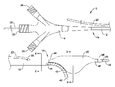
FIG. 1 is a side plan view of an exemplary catheter apparatus for
recanalization of a
blood vessel;
FIG. 2A is an exemplary cross-sectional view of the catheter shaft of FIG. 1
taken
along line 2-2;
FIG. 2B is an alternative cross-sectional view of the catheter shaft of FIG. 1
taken
along line 2-2;
FIG. 3 is a cross-sectional view of the catheter apparatus of FIG. 1 taken
along line 3-
3;
FIG. 4 is a side plan view of the distal portion of the catheter apparatus of
FIG. 1 in a
delivery configuration;
FIG. 5 is a cross-sectional view of the catheter apparatus of FIG. 4 taken
along line 5-
5;
FIG. 6 is a side plan view of an alternative embodiment of the distal portion
of the
catheter apparatus of FIG. 1 in a deflected configuration;
FIG. 7 illustrates possible curved or deflected configurations of the distal
portion of
the catheter apparatus for re-entry into a true lumen of a blood vessel;
FIG. 8 is a cross-sectional view of the catheter apparatus positioned in the
subintimal
space of a blood vessel;
FIGS. 9-14 illustrate aspects of an exemplary method for recanalizing an
occluded
blood vessel using the catheter apparatus of FIG. 1; and
FIGS. 15-16 illustrate aspects of another exemplary method for recanalizing an
occluded blood vessel using the catheter apparatus of FIG. 1.
While the aspects of the disclosure are amenable to various modifications and
alternative forms, specifics thereof have been shown by way of example in the
drawings and
will be described in detail. It should be understood, however, that the
intention is not to limit
aspects of the disclosure to the particular embodiments described. On the
contrary, the
intention is to cover all modifications, equivalents, and alternatives falling
within the spirit
and scope of the disclosure.
CA 02848781 2014-03-13
WO 2013/043592
PCT/US2012/055905
4
DETAILED DESCRIPTION
For the following defined terms, these definitions shall be applied, unless a
different
definition is given in the claims or elsewhere in this specification.
All numeric values are herein assumed to be modified by the term "about",
whether or
not explicitly indicated. The term "about" generally refers to a range of
numbers that one of
skill in the art would consider equivalent to the recited value (i.e., having
the same function
or result). In many instances, the term "about" may be indicative as including
numbers that
are rounded to the nearest significant figure.
The recitation of numerical ranges by endpoints includes all numbers within
that
range (e.g., 1 to 5 includes 1, 1.5, 2, 2.75, 3, 3.80, 4, and 5).
Although some suitable dimensions, ranges and/or values pertaining to various
components, features and/or specifications are disclosed, one of skill in the
art, incited by the
present disclosure, would understand desired dimensions, ranges and/or values
may deviate
from those expressly disclosed.
As used in this specification and the appended claims, the singular forms "a",
"an",
and "the" include plural referents unless the content clearly dictates
otherwise. As used in
this specification and the appended claims, the term "or" is generally
employed in its sense
including "and/or" unless the content clearly dictates otherwise.
The following detailed description should be read with reference to the
drawings in
which similar elements in different drawings are numbered the same. The
detailed
description and the drawings, which are not necessarily to scale, depict
illustrative
embodiments and are not intended to limit the scope of the disclosure. The
illustrative
embodiments depicted are intended only as exemplary. Selected features of any
illustrative
embodiment may be incorporated into an additional embodiment unless clearly
stated to the
contrary.
An exemplary recanalization catheter 10 is illustrated at FIG. 1. The
recanalization
catheter 10 may include a main catheter shaft 12 extending from a hub assembly
14 at a
proximal end 16 of the catheter shaft 12 to an expandable member, shown as an
inflatable
balloon 20 mounted on a distal portion of the catheter shaft 12 proximate the
distal end 18 of
the catheter shaft 12. Although the expandable member is illustrated as an
inflatable balloon
20, in some embodiments the expandable member may be an expandable framework
formed
of one or more, or a plurality of struts which may be automatically or
manually expanded, or
other manually expandable or automatically expandable structure.
CA 02848781 2014-03-13
WO 2013/043592
PCT/US2012/055905
The catheter 10 may be configured to be advanced over a guidewire 22 for
delivery to
a remote location in the vasculature of a patient. For example, in some
instances the catheter
may be configured as a single-operator-exchange (SOE) catheter having a
guidewire
lumen 24 extending from a distal port 26 to a proximal guidewire port 28
located a short
5 distance proximal of the balloon 20 and distal of the hub assembly 14. In
such a
configuration, the guidewire 22 may extend through the guidewire lumen 24
between the
distal port 26 and the proximal port 28, and extend along an exterior of the
catheter shaft 12
proximal of the proximal port 28 to the proximal end 16 of the catheter shaft
12. In other
instances, the catheter 10 may be configured as an over-the-wire (OTW)
catheter having a
10 guidewire lumen 24 extending through the entire length of the catheter
10 from a distal port
26 at a distal tip of the catheter 10 to a proximal guidewire port 30 in the
hub assembly 14.
FIG. 1 illustrates such a configuration with the proximally extending portion
of the guidewire
22 in dashed lines. It is noted that in instances in which the catheter 10 is
an SOE catheter,
the hub assembly 14 may not include a proximal guidewire port 30 and/or in
instances in
which the catheter 10 is an OTW catheter, the proximal guidewire port 28 may
not be
present.
The catheter shaft 12 may also include an inflation lumen 32 extending from an
inflation port 34 of the hub assembly 14 to an interior of the balloon 20. The
inflation lumen
32 may be configured for delivering inflation fluid to the balloon 20 to
inflate the balloon 20
during a medical procedure.
The catheter 10 may also include a flexible tubular member 40 extending from
the
main catheter shaft 12 through opening 44. For example, in some instances the
opening 44
may be a side opening extending through a sidewall of a tubular member of the
main catheter
shaft 12, or the opening 44 may be a distal opening at the distal end of a
tubular member of
the main catheter shaft 12. The flexible tubular member 40 may extend along a
portion of the
exterior of the balloon 20, such that an exterior surface of the balloon 20
may engage the
flexible tubular member 40 when the balloon 20 is inflated. The flexible
tubular member 40
may extend from the main catheter shaft 12 at a location proximal of the
balloon 20, and
extend distally therefrom, such that the flexible tubular member 40 extends
exterior of the
proximal waist 46 of the balloon 20, which may be secured to a portion of the
main catheter
shaft 12. In some instances, the distal tip 42 of the flexible tubular member
40 may terminate
proximal of the distal waist 48 of the balloon 20, which may be secured to a
portion of the
main catheter shaft 12.
CA 02848781 2014-03-13
WO 2013/043592
PCT/US2012/055905
6
The flexible tubular member 40, which may be considered a deflectable re-entry
tube
or redirection tube (e.g., a "stinger") in some instances, may include
flexibility characteristics
permitting the flexible tubular member 40 to be deflected away from the main
catheter shaft
12 (e.g., away from the central longitudinal axis of the main catheter shall
12) into a curved
or deflected configuration. In some instances, the flexible tubular member 40
may include
one or more, or a plurality of cuts or slits formed through the sidewall of
the flexible tubular
member 40, providing the flexible tubular member 40 with a degree of lateral
flexibility. For
example, the flexible tubular member 40 may include a helical cut or slit
formed through the
sidewall of the flexible tubular member 40 and extending along a length of the
flexible
tubular member 40, an arrangement of a plurality of cuts or slits formed
through the sidewall
of the flexible tubular member 40 and extending partially around the
circumference of the
flexible tubular member 40 along a length of the flexible tubular member 40,
or another
arrangement of cuts or slits formed in another fashion to provide a desired
degree of lateral
flexibility.
In some embodiments, the flexible tubular member 40 may be formed of a
metallic
material, including a stainless steel or a nickel-titanium alloy such as
nitinol, a polymeric
material such as polyamide, polyether block amide, polyethylene, or
polyethylene
terephthalate, or a combination of metallic and polymeric materials, for
example.
The flexible tubular member 40 may define a third, device delivery lumen 38
configured for delivering an elongated medical device to a target location via
the catheter 10.
The device delivery lumen 38 may extend from an access port 36 in the hub
assembly 14
through the main catheter shaft 12 to the distal tip 42 of the flexible
tubular member 40.
Accordingly an elongated medical device may be inserted through the device
delivery lumen
38 to be advanced from the distal tip 42 of the flexible tubular member 40
during a medical
procedure.
In some embodiments, as shown in FIG. 2A, the catheter shaft 12, or a portion
thereof, may include an outer tubular member 50, a first inner tubular member
52 extending
through the outer tubular member 50, and a second inner tubular member 54
extending
through the outer tubular member 50. The first inner tubular member 52 may
define the
guidewire lumen 24, and the second inner tubular member 54 may define the
device delivery
lumen 38. The second inner tubular member 54 may be an extension of the
flexible tubular
member 40 extending into the outer tubular member 50, or the second tubular
member 54
may be secured to the flexible tubular member 40 and extend therefrom,
providing the device
delivery lumen 38 therein. In such embodiments, the main catheter shaft 12 may
be
CA 02848781 2014-03-13
WO 2013/043592
PCT/US2012/055905
7
configured such that the proximal waist 46 of the balloon 20 is secured to the
distal end of the
outer tubular member 50, while the distal waist 48 of the balloon 20 is
secured to the distal
end of the first inner tubular member 52, extending through the interior of
the balloon 20.
Furthermore, the inflation lumen 32 may be defined between the outer tubular
member 50
and the first and second inner tubular members 52, 54.
In other embodiments, as shown in FIG. 2B, the catheter shaft 12, or a portion
thereof,
may be an extruded shaft 56 having a plurality of lumens formed therein. For
example, the
extruded shaft 56 may include the guidewire lumen 24, the inflation lumen 32,
and the device
delivery lumen 38. In such embodiments, the main catheter shaft 12 may be
configured such
that the proximal waist 46 of the balloon 20 is secured to a portion of the
extruded shaft 56,
while the distal waist 48 of the balloon 20 is secured to another portion of
the extruded shaft
56 or a tubular member extending therefrom, extending through the interior of
the balloon 20.
The catheter 10 may also include a distal tip 58 extending distally from the
balloon
20. The distal tip 58 may have a lumen extending therethrough and opening out
to the distal
port 26 at the distal end thereof to accommodate the guidewire 22 extending
from the distal
port 26. In some instances, the distal tip 58 may be an atraumatic tip, such
as a flexible, low
durometer tip similar to tips provided with typical angioplasty balloon
catheters. However, in
other embodiments, the distal tip 58 may be configured to facilitate piercing
and/or dissection
of tissue layers of the blood vessel. For example, the distal tip 58 may
include a sharp, rigid
and/or piercing feature. In one embodiment, as shown in FIG. 1, the distal tip
58 may include
an angled distal edge, providing the distal tip 58 with a sharpened cutting or
piercing edge.
FIG. 3 is a cross-sectional view of the catheter 10 taken through the balloon
20. As
shown in FIG 3, when inflated, the balloon 20 may include a central bulbous
portion 60, a
first wing portion 62 extending from the bulbous portion 60 in a first
direction, and a second
wing portion 64 extending from the bulbous portion 60 is a second direction,
generally
opposite the first direction. Thus the first and second wing portions 62, 64
may extend
outwardly in opposing directions from the central bulbous portion 60. In some
instances, the
balloon 20 may be formed of a non-distensible or stiffer material, such that
when the balloon
20 is inflated, the balloon 20 maintains the bulbous portion 60 and wing
portions 62, 64
shown in FIG. 3. The winged portions 62, 64 may be configured to follow the
curvature of a
vessel wall, and thus generally orient the flexible tubular member 40 toward
the center of the
true lumen of the vessel during use. Furthermore, the bulbous portion 60 may
be configured
to contact and press against the flexible tubular member 40, thereby
deflecting the flexible
tubular member 40 upon inflation of the balloon 20.
CA 02848781 2014-03-13
WO 2013/043592
PCT/US2012/055905
8
FIGS. 4 and 5 illustrate an exemplary arrangement of the catheter 10 with the
balloon
20 deflated and in a delivery configuration. As shown, the deflated balloon 20
may be folded
around the flexible tubular member 40 to provide the distal portion of the
catheter 10 with a
small delivery profile. For example, in some instances, in the folded delivery
configuration,
the catheter 10 may have an outer diameter of about 3 French (1 mm) to about 5
French (1.67
mm), for example about 3 French (1 mm), about 3.5 French (1.17 mm), about 4
French (1.33
mm), about 4.5 French (1.5 mm) or about 5 French (1.67 mm). In some
embodiments, the
distal tip 42 of the flexible tubular member 40 may be wrapped within the
folds of the
balloon 20 to cover and protect the distal tip 42 from inadvertent contact
with the vessel wall
during delivery of the balloon 20 and flexible tubular member 40 to a target
location in the
vasculature. For example, as shown in FIG. 5, portions of balloon material
forming the
wings 62, 64 may be folded around the flexible tubular member 40 to maintain
the flexible
tubular member 40 in an elongated configuration generally parallel to the
central longitudinal
axis of the catheter shaft 12.
FIG. 6 illustrates an alternative embodiment, in which the catheter 10
includes a pull
wire 70, or other actuation mechanism to facilitate deflecting the flexible
tubular member 40
into a curved configuration. For example, the pull wire 70 may have a distal
end secured to a
distal portion of the flexible tubular member 40 proximate the distal tip 42
of the flexible
tubular member 40. Accordingly, the pull wire 70 may extend to the proximal
end of the
catheter 10, or be attached to an actuatable component accessible at the
proximal end of the
catheter 10, to be manipulated by the operator to deflect the flexible tubular
member 40 into a
curved configuration.
As shown in FIG. 7, the flexible tubular member 40 may be configured to be
curved
or deflected from a generally axially aligned configuration A in which the
flexible tubular
member 40 extends along a central longitudinal axis Y generally parallel to
the central
longitudinal axis X of the main catheter shaft 12 to a curved configuration in
which the distal
portion of the flexible tubular member 40 is curved away from the longitudinal
axis Y. For
example, in some embodiments, the distal portion of the flexible tubular
member 40 may be
curved or deflected to a curved configuration B having an angle of curvature
(i.e., arc angle)
01 of less than 90 , for example about 30 , about 45 , or about 60 , in some
instances. In
other embodiments, the distal portion of the flexible tubular member 40 may be
curved or
deflected to a curved configuration C having an angle of curvature (i.e., arc
angle) 02 of about
90 . In still other embodiments, the distal portion of the flexible tubular
member 40 may be
curved or deflected to a curved configuration D having an angle of curvature
(i.e., arc angle)
CA 02848781 2014-03-13
WO 2013/043592
PCT/US2012/055905
9
03 of greater than 90 , for example about 950 or more, about 1000 or more, or
about 105 or
more in some instances. As described herein, the "arc angle" or "angle of
curvature" is
intended to be the angle through which the distal portion of the flexible
tubular member 40
curves through from the point along the longitudinal axis Y in which the
flexible tubular
member 40 begins to curve away from the longitudinal axis Y to the center of
the opening at
the distal tip 42 of the flexible tubular member 40.
In some embodiments, such as embodiments in which the distal tip 42 includes a
tapered or sharpened tip, the opening of the lumen 38 at the distal tip 42 may
face in a
proximal direction in the curved configuration. For instance, the opening of
the lumen 38 at
the distal tip 42 may face in a proximal direction when the distal portion of
the flexible
tubular member 40 is deflected through an arc angle of 90 or more, 95
degrees or more,
100 degrees or more, or 105 degrees or more. Accordingly, in such an
embodiment, an
elongate medical device advanced out of the distal opening of the lumen 38 of
the flexible
tubular member 40 may be directed in a proximal or retrograde direction, for
example.
FIG. 8 is a cross-sectional view of the distal portion of the catheter 10
positioned in a
subintimal space created between two tissue layers of a vessel wall 80. The
blood vessel 80
typically has three tissue layers, an innermost layer or intima layer (i.e.,
tunica intima) 82, an
intermediate layer or media layer (i.e., tunica media) 84, and an outermost
layer or adventitia
layer (tunica adventitia) 86, with the media layer 84 positioned between the
intima layer 80
and the adventitia layer 86. The intima layer 82 is a layer of endothelial
cells lining the
lumen 88 of the vessel 80, as well as a subendothelial layer made up of mostly
loose
connective tissue. The media
layer 84 is a muscular layer formed primarily of
circumferentially arranged smooth muscle cells. The adventitia layer 86, which
forms the
exterior layer of the vessel wall 80 is formed primarily of loose connective
tissue made up of
fibroblasts and associated collagen fibers.
As will be described further herein, the distal portion of the catheter 10,
including the
balloon 20, may be advanced into a subintimal space (i.e., a space between the
intima layer
82 and the adventitia layer 86) created in the vessel wall 80, such as through
dissection of the
tissue layers of the vessel wall 80. Once positioned in the subintimal space,
the balloon 20
may be inflated between the intima layer 82 and the adventitia layer 86 of the
vessel wall 80.
As the balloon 20 is inflated, the wings 62, 64 of the balloon 20 may be
unfolded and inflated
between the intima layer 82 and the adventitia layer 86 to orient the flexible
tubular member
radially inward of the bulbous portion 60 of the balloon 20. Furthermore, the
bulbous
portion 60 of the balloon 20 may be inflated to press against the flexible
tubular member 40
CA 02848781 2014-03-13
WO 2013/043592
PCT/US2012/055905
to deflect the flexible tubular member 40 toward the true lumen 88 of the
vessel 80. Inflation
of the bulbous portion 60 against the flexible tubular member 40 may cause the
distal tip 42
of the flexible tubular member 40 to pierce through the intima layer 82 into
the true lumen 88
to allow re-entry into the true lumen 88 with an elongate medical device
advanced through
5 the lumen 38. Because the external adventitia layer 86 is more inelastic
than the internal
intima layer 82, the forces generated through inflation of the balloon 20 may
cause the
internal intima layer 82 to yield first, bending or folding towards the true
lumen 88, rather
than causing the external adventitia layer 86 to stretch.
In some instances, it may be undesired, difficult or impossible to pass
through an
10 occlusion, such as a chronic total occlusion (CTO) in a lumen of a blood
vessel with a
medical device to recanalize the vessel. In such instances, it may be possible
to recanalize
the blood vessel through a subintimal approach using the catheter 10. Turning
to FIGS. 9-14,
several aspects of an exemplary method for recanalizing an occluded blood
vessel using the
catheter 10 are illustrated. As shown in FIG. 9, a guidewire 22 may initially
be advanced
through the lumen 88 of the vessel 80 to a location proximate a proximal end
of an occlusion
90 blocking the lumen 88. The guidewire 22 may then be advanced to penetrate
outward
through the intima layer 82 at a location proximal of the proximal end of the
occlusion 90
into the vessel wall 80. With the tip of the guidewire 22 located between the
intima layer 82
and the adventitia layer 86, the guidewire 22 may be further advanced distally
in a subintimal
manner to create a subintimal space between the intima layer 82 and the
adventitia layer 86.
As shown in FIG. 10, the guidewire 22 may be advanced in a subintimal manner
until the
distal tip of the guidewire 22 is located distal of the distal end of the
occlusion 90 in the
subintimal space created, such as by dissection of the tissue layers of the
vessel wall 80.
The recanalization catheter 10 may then be advanced distally over the
guidewire 22
from the true lumen 88 proximal of the occlusion 90, into the subintimal space
between the
intima layer 82 and the adventitia layer 86, to a position in the subintimal
space in which the
distal portion of the catheter 10, including the balloon 20, is located distal
of the distal end of
the occlusion 90, as shown in FIG. 11. The recanalization catheter 10 may be
advanced
through the subintimal space in a delivery configuration, such as with the
balloon 20 in a
deflated, folded configuration wrapped around the flexible tubular member 40
extending
from the main catheter shaft 12. In some instances in which the distal tip 58
of the catheter
10 is configured to facilitate piercing and/or dissection of tissue layers of
the blood vessel, the
sharp, rigid or piercing feature of the distal tip 58 may be used to pierce
and/or dissect tissue
layers of the vessel wall 80 as the catheter 10 is advanced distally.
CA 02848781 2014-03-13
WO 2013/043592
PCT/US2012/055905
11
With the balloon 20 positioned distal of the distal end of the occlusion 90,
the balloon
20 may be inflated in the subintimal space formed between the intima layer 82
and the
adventitia layer 86, as shown in FIG. 12. As the balloon 20 is inflated, the
wings 62, 64 of
the balloon 20 may be unfolded and inflated between the intima layer 82 and
the adventitia
layer 86 to orient the flexible tubular member 40 radially inward of the
bulbous portion 60 of
the balloon 20. Furthermore, the bulbous portion 60 of the balloon 20 may be
inflated to
press against the flexible tubular member 40 to deflect the flexible tubular
member 40 toward
the true lumen 88 of the vessel 80. Inflation of the bulbous portion 60
against the flexible
tubular member 40 may cause the distal tip 42 of the flexible tubular member
40 to pierce
through the intima layer 82 and thus re-enter into the true lumen 88 to allow
re-entry into the
true lumen 88 distal of the occlusion 90 with an elongate medical device
advanced through
the lumen 38. In some instances, the pull wire 70 may be actuated to
facilitate and/or
augment curving the flexible tubular member 40 into a curved configuration.
The distal
portion of the main catheter shaft 12, including the distal tip of the main
catheter shaft 12 and
the balloon 20, as well as the guidewire 22, may remain positioned in the
subintimal space
after the flexible tubular member 40 is deflected into the curved
configuration and penetrates
into the true lumen 88.
As described above, the flexible tubular member 40 may be configured to be
curved
or deflected from a generally axially aligned configuration in which the
flexible tubular
member 40 extends parallel to the main catheter shaft 12 to a curved
configuration in which
the distal portion of the flexible tubular member 40 is curved away from the
longitudinal axis
of the main catheter shaft 12. For example, in some embodiments, as shown in
FIG. 12, the
distal portion of the flexible tubular member 40 may be curved or deflected to
a curved
configuration having an angle of curvature (i.e., arc angle) of about 90 or
greater than 90 ,
for example about 950 or more, about 1000 or more, or about 105 or more in
some instances.
An elongate medical device 100 may then be advanced through the device
delivery
lumen 38 of the catheter 10 and exit the flexible tubular member 40 into the
true lumen 88
distal of the occlusion 90 through the opening in the distal tip 42 of the
flexible tubular
member 40, shown in FIG. 13. In the embodiment shown in FIG. 13, the flexible
tubular
member 40 may be curved such that the distal opening of the lumen 38 at the
distal tip 42 of
the flexible tubular member 40 faces in a proximal direction, and thus faces
the distal end of
the occlusion 90. Accordingly, the elongate medical device 100, upon exiting
the flexible
tubular member 40, may be directed or advanced proximally toward the distal
end of the
occlusion 90. In instances in which the elongate medical device 100 is an
occlusion crossing
CA 02848781 2014-03-13
WO 2013/043592
PCT/US2012/055905
12
device, such as an atherectomy device, a needle-tipped catheter, a stylet or a
guidewire, the
elongate medical device may be directed or advanced proximally from the distal
opening of
the lumen 38 of the flexible tubular member 40 toward the distal end of the
occlusion 90 to
penetrate into or through the occlusion 90 in a retrograde manner.
As shown in FIG. 13, in some instances the elongate medical device 100 may be
an
atherectomy device having an elongate shaft 104 with a distal cutting tip 102
attached thereto
for penetrating into or through the occlusion 90. For example, in some
instances, the distal
cutting tip 102 may be a rotatable cutting tip or burr, such as a micro burr,
expandable burr,
an angled burr, an enhanced wire tip burr, a diamond coated burr, or other
cutting device. In
other instances, the distal cutting tip 102 may be an ablation electrode or
ultrasound
transducer configured for ablating a pathway through the occlusion 90.
From the re-entry location distal of the occlusion 90, the elongate medical
device 100
(e.g., occlusion crossing device) may be advanced in a retrograde direction
(i.e., proximally)
into the distal end of the occlusion 90. In such a fashion, the elongate
medical device 100
may be advanced through the occlusion 90 from the distal end of the occlusion
90 to the
proximal end of the occlusion 90 in a retrograde manner, as shown in FIG. 14,
to create a
pathway through the occlusion 90 to recanalize the vessel and provide a
pathway through the
occlusion 90 for blood to flow therethrough.
In a retrograde approach of crossing the occlusion 90 in such a manner, there
may be
less concern with the fluid flow and circumstances associated therewith. For
example,
emboli created while boring or ablating through the occlusion 90 may flow
distally away
from the occlusion 90 as the atherectomy device is advanced through the
occlusion 90.
In other embodiments, such as shown in FIG. 15, the balloon 20 may be inflated
in
the subintimal space formed between the intima layer 82 and the adventitia
layer 86 to deflect
the flexible tubular member 40 into a curved configuration by inflating the
bulbous portion
60 of the balloon 20 against the flexible tubular member 40 to deflect the
flexible tubular
member 40 toward the true lumen 88 of the vessel 80. Inflation of the bulbous
portion 60
against the flexible tubular member 40 may cause the distal tip 42 of the
flexible tubular
member 40 to pierce through the intima layer 82 and thus re-enter into the
true lumen 88 to
allow re-entry into the true lumen 88 distal of the occlusion 90 with an
elongate medical
device advanced through the lumen 38. In some instances, the pull wire 70 may
be actuated
to facilitate and/or augment curving the flexible tubular member 40 into a
curved
configuration. The distal portion of the main catheter shaft 12, including the
distal tip of the
main catheter shaft 12 and the balloon 20, as well as the guidewire 22, may
remain positioned
84139385
13
in the subintimal space after the flexible tubular member 40 is deflected into
the curved
configuration and penetrates into the true lumen 88.
Alternatively, inflation of the bulbous portion 60 against the flexible
tubular member 40
may cause the distal tip 42 of the flexible tubular member 40 to be oriented
toward the intima
layer 82 and an elongate medical device, such as a guidewire, a stylet, a
needle, or other device
may be advanced through the flexible tubular member 40 to pierce through the
intima layer 82 to
re-enter into the true lumen 88 distal of the occlusion 90.
As described above, the flexible tubular member 40 may be configured to be
curved or
deflected from a generally axially aligned configuration in which the flexible
tubular member 40
extends parallel to the main catheter shaft 12 to a curved configuration in
which the distal portion
of the flexible tubular member 40 is curved away from the longitudinal axis of
the main catheter
shaft 12. For example, as shown in FIG. 15, the distal portion of the flexible
tubular member 40
may be curved or deflected to a curved configuration having an angle of
curvature (i.e., arc angle)
of less than 90 such that the distal opening of the lumen 38 at the distal
tip 42 of the flexible
tubular member 40 faces in a distal direction.
An elongate medical device 122 may then be advanced through the device
delivery
lumen 38 of the catheter 10 and exit the flexible tubular member 40 into the
true lumen 88
distal of the occlusion 90 through the opening in the distal tip 42 of the
flexible tubular
member 40, shown in FIG. 16. In the embodiment shown in FIG. 16, the flexible
tubular
member 40 may be curved such that the distal opening of the lumen 38 at the
distal tip 42 of the
flexible tubular member 40 faces in a distal direction, and thus faces away
from the distal end of
the occlusion 90. Accordingly, the elongate medical device 100, upon exiting
the flexible tubular
member 40, may be directed or advanced distally through the true lumen 88 away
from the distal
end of the occlusion 90.
Once a pathway has been created across the occlusion 90, either through the
occlusion 90
and/or around the occlusion 90 via a subintimal track, one or more additional
medical devices may
be advanced through the blood vessel 80 to enlarge the pathway and/or pass
distally of the
occlusion 90 to perform a further medical procedure.
Those skilled in the art will recognize that aspects of the present disclosure
may be
manifested in a variety of forms other than the specific embodiments described
and
contemplated herein. Accordingly, departure in form and detail may be made
without
departing from the scope and spirit of the present disclosure as described in
the appended
claims.
CA 2848781 2018-03-09