Note : Les descriptions sont présentées dans la langue officielle dans laquelle elles ont été soumises.
CA 02848835 2014-04-09
DocketNo.PKOA-13486-PCT
1
DESCRIPTION
MANAGEMENT SYSTEM AND MANAGEMENT METHOD OF MINING MACHINE
Field
[0001] The present invention relates to a management
system and a management method of a mining machine.
Background
[0002] In mining sites in a mine, mining machines such
as a hydraulic excavator and a dump track operate. In
these years, information about a mining machine is acquired
via wireless communications. Patent Literature 1 discloses
a technique in which a traveling state of a mobile unit is
acquired using a GPS (Global Positioning System).
Citation List
Patent Literature
[0003] Patent Literature 1: Japanese Laid-open Patent
Publication No. 2009-217554
Summary
Technical Problem
[0004] In these years, a user demand is increasing that
preventive maintenance is performed on mining machines and
the guidance of driving mining machines is performed in
consideration of fuel consumption and productivity. For
the purpose of preventive maintenance, it is necessary to
suppress inappropriate manipulations and drives, which
possibly damage the components of the mining machine. To
this end, it is necessary to monitor what manipulation and
drive are performed at which position on a traveling route
and what vehicle abnormality state occurs. Moreover, in
order to guide driving in consideration of fuel consumption
and productivity, it is necessary to monitor what
manipulation and drive are performed at which position on a
traveling route, which possibly impair fuel consumption and
productivity, and what vehicle state occurs. Therefore, it
CA 02848835 2014-04-09
DocketNo.PKOA-13486-PCT
2
is desired to appropriately and easily grasp what problem
occurs at which position on the route of the mining machine.
[0005] An object of the present invention is to provide
a management system and a management method of a mining
machine that can easily grasp an inappropriate drive and a
vehicle abnormality state that occur on a route in a mine,
the content of the vehicle state, for example, and the
occurrence position at a glance.
Solution to Problem
[0006] According to the present invention, a mining
machine management system comprises: a position information
detector which is mounted on a mining machine enabled to
travel on a route in a mine and detects position
information about the mining machine; an operation
information detector which is mounted on the mining machine
and detects operation information about the mining machine;
and a processor which obtains accumulated data of the
operation information in a predetermined section of the
route based on the position information and the operation
information.
[0007] The operation information can include an
abnormality of the mining machine.
[0008] The mining machine management system can further
comprise an output device which outputs the accumulated
data together with the route in an image in association
with the predetermined section of the route.
[0009] The image can be outputted to an inside of a mesh
in a grid.
[0010] The output device can output images in different
designs based on an accumulation degree of the accumulated
data.
[0011] The operation information can include first
operation information and second operation information; and
CA 02848835 2016-04-28
3
the output device can output images in different designs
between accumulated data of the first operation information
and accumulated data of the second operation information.
[0012] The design can include at least one of a color,
shape, and size.
[0013] The mining machine management system can comprise an
evaluation device which evaluates an operation state of the
mining machine in the predetermined section based on the
accumulated data.
[0014] According to the present invention, a management
method of a mining machine comprise: detecting position
information about a mining machine on a route, the mining
machine being enabled to travel on the route in a mine;
detecting operation information on the route of the mining
machine; and obtaining accumulated data of a plurality of
items of the operation information in a predetermined
section of the route based on the position information and the
operation information.
[0015] The accumulated data can be outputted together with
the route in an image in association with the predetermined
section of the route.
[0016] An operation state of the mining machine in the
predetermined section can be evaluated based on the
accumulated data.
[0017] According to the present invention, it is possible to
easily grasp an inappropriate drive and a vehicle abnormality
state that occur on the route in the mine, the content of the
vehicle state, for example, and the occurrence position at a
glance.
[0017a] Accordingly, in one aspect, the present invention
resides in a mining machine management system comprising: a
position information detector which is mounted on a mining
machine enabled to travel on a route in a mine and detects
CA 02848835 2016-04-28
3a
position information about the mining machine; an operation
information detector which is mounted on the mining machine and
detects operation information about the mining machine; a
processor which divides a predetermined section of the route by
meshes in grids along a horizontal plane and obtains
accumulated data of a plurality of items of the operation
information in respective sections of the route included in
inner sides of the meshes based on the operation information in
association with the position information; and an output device
which outputs the accumulated data together with the route in
an image in association with the mesh, wherein the accumulated
data of the operation information includes accumulated data of
at least one of information about an abnormal drive,
information about a vehicle error, and information about a
specific drive manipulation.
[0017b] In another aspect, the present invention resides in a
management method of a management system of a mining machine
including a position information detector which is mounted on a
mining machine enabled to travel on a route in a mine and
detects position information about the mining machine; an
operation information detector which is mounted on the mining
machine and detects operation information about the mining
machine; a processor having a computer; and an output device
connected to the processor, the management method comprising:
detecting, by the position information detector, position
information about the mining machine on the route; detecting,
by the operation information detector, operation information on
the route of the mining machine; and dividing a predetermined
section of the route by meshes in grids along a horizontal
plane and obtaining, by the processor, accumulated data of a
plurality of items of the operation information in respective
sections of the route included in inner sides of the meshes
based on the operation information in association with the
CA 02848835 2016-04-28
,
3b
position information, wherein the accumulated data of the
operation information includes accumulated data of at least one
of information about an abnormal drive, information about a
vehicle error, and information about a specific drive
manipulation, and wherein the accumulated data is outputted to
the output device together with the route in an image in
association with the mesh.
Brief Description of Drawings
[0018]
FIG. 1 is a diagram of an exemplary a mining machine
management system according to an embodiment.
FIG. 2 is a diagram of an exemplary management
CA 02848835 2014-04-09
DocketNo.PKOA-13486-PCT
4
apparatus according to the embodiment.
FIG. 3 is a diagram of an exemplary dump track
according to the embodiment.
FIG. 4 is a diagram of an exemplary on-vehicle
processor, on-vehicle storage device, position information
detector, and operation information detector according to
the embodiment.
FIG. 5 is a diagram of an exemplary route on which a
dump track has traveled.
FIG. 6 is a diagram of exemplary items of information
about a registered route according to the embodiment.
FIG. 7 is a diagram of an exemplary display screen
according to the embodiment.
FIG. 8 is a diagram of an exemplary display screen
according to the embodiment.
FIG. 9 is a diagram of an exemplary display screen
according to the embodiment.
FIG. 10 is a diagram of an exemplary display screen
according to the embodiment.
FIG. 11 is a diagram of an exemplary display screen
according to the embodiment.
FIG. 12 is a diagram of an exemplary display screen
according to the embodiment.
Description of Embodiments
[0019] In the following, an embodiment of the present
invention will be described with reference to the drawings.
However, the present invention is not limited thereto.
[0020] <The Outline of a Mining machine management
system>
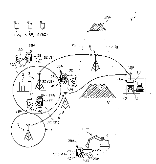
FIG. 1 is a diagram of a site to which a mining
machine management system according to an embodiment is
applied. A management system 1 for a mining machine
manages the operations of mining machines or evaluates the
CA 02848835 2014-04-09
DocketNo.PKOA-13486-PCT
productivity or the manipulation technique, for example, of
the operator of the mining machine, and performs preventive
maintenance and abnormality diagnosis, for example, of dump
tracks. To this end, the management system 1 identifies a
5 route on which a dump track 20 has traveled, and stores the
route as route information. In the following, it is
defined that the traveling route includes the route on
which the dump track 20 has traveled and places to stop.
In the following, the traveling route is appropriately
referred to as a route.
[0021] The mining machine is a generic term of machines
for use in various work operations in a mine. In the
embodiment, for one kind of trucks of the mining machines,
the dump track 20 is taken as an example, which carries
crushed stones or dirt or rocks produced in mining crushed
stones, for example, as a load. However, the mining
machine according to the embodiment is not limited to the
dump track. For example, the mining machine according to
the embodiment may be a digging machine that mines crushed
stones, for example, and a hydraulic excavator, electric
shovel, or wheel loader functioning as a loader that loads
a load on the dump track 20. In the embodiment, the dump
track 20 is a manned mining machine that travels and
unloads a load by the manipulation by an operator. However,
the dump track 20 is not limited to such a vehicle. For
example, the dump track 20 may be an unattended dump track
whose operation is managed by the management system 1.
[0022] In the mine, the dump track 20 is loaded with
rocks or dirt, for example, by a loader 4 such as a
hydraulic excavator at a place (in the following, a loading
site) LPA at which a loading operation is performed. The
dump track 20 then unloads the loaded rocks or dirt, for
example, at a place (in the following, an unloading site)
CA 02848835 2014-04-09
DocketNo.PKOA-13486-PCT
6
DPA at which the load is unloaded. The dump track 20 moves
between the loading site LPA and the unloading site CPA as
traveling on routes Rg and Rr.
[0023] <The Outline of a Mining machine management
system>
In the management system for the mining machine (in
the following, appropriately referred to as the management
system) 1, a management apparatus 10 collects information
about the position of the dump track 20 as a mining machine
(in the following, referred to as position information) and
information about an operation state (in the following,
referred to as operation information) from the dump track
via wireless communications. Different from the dump
track 20, which is a mobile unit, the management apparatus
15 10 is disposed on the management facility of the mine, for
example. As described above, the management apparatus 10
is not intended for mobile use in principle. The
information collected at the management apparatus 10
includes position information about the dump track 20 (the
20 coordinates of the latitude, the longitude, and the
altitude) and operation information about the dump track 20.
For example, the operation information is at least one of
the traveling time, the distance covered, the engine water
temperature, the presence or absence of an abnormality, the
location of an abnormality, the fuel consumption rate, the
loadage (a vehicle live load), and so on. The position
information and the operation information are mainly used
for creating the traveling route map of the dump track 20,
traveling route mapping, drive evaluation, preventive
maintenance, and abnormality diagnosis, for example.
Therefore, the position information and the operation
information are useful for cooping with needs such as the
improvement of productivity in the mine or the improvement
CA 02848835 2014-04-09
DocketNo.PKOA-13486-PCT
7
of operations in the mine. The operation information will
be described later in detail.
[0024] The management system 1 includes a position
information detector 29 that is mounted on the dump track
20 and detects position information about the dump track 20,
an operation information detector 40 that is mounted on the
dump track 20 and detects operation information about the
dump track 20, an on-vehicle processor 30 that is mounted
on the dump track 20 and performs various processes related
to management, an on-vehicle storage device 31 that is
mounted on the dump track 20 and stores various items of
information about management, a management side processor
12 that is provided on the management apparatus 10 and
performs various processes related to management, and a
management side storage device 13 that is provided on the
management apparatus 10 and stores various items of
information about management.
[0025] The on-vehicle processor 30 processes position
information and operation information about the dump track
20. The on-vehicle storage device 31 stores position
information and operation information about the dump track
20.
[0026] The management side processor 12 processes
position information and operation information about the
dump track 20. The management side storage device 13
stores position information and operation information about
the dump track 20.
[0027] In the embodiment, the management system 1 makes
reference to position information about a route (a
registered route) registered (stored) on one or both of the
management side storage device 13 and the on-vehicle
storage device 31 (in the following, referred to as route
information), and identifies the actual traveling route by
CA 02848835 2014-04-09
DocketNo.PKOA-13486-PCT
8
determining whether to match position information about a
route on which the dump track 20 has actually traveled (an
actual traveling route) derived from the result detected at
the position information detector 29 with the registered
route.
[0028] In the embodiment, the management system 1
acquires operation information about the dump track 20
derived from the result detected at the operation
information detector 40 in association with position
information about the dump track 20 detected at the
position information detector 29. The management system 1
finds the accumulated data of a plurality of items of
operation information in a predetermined section of the
route on which the dump track 20 has traveled based on the
acquired position information and the operation information
about the dump track 20. The management system 1 evaluates
the operation state of the dump track 20 in a predetermined
section of the route based on the found accumulated data.
Moreover, the management system 1 stores the found
accumulated data on one or both of the management side
storage device 13 and the on-vehicle storage device 31.
[0029] The operation information about the dump track 20
includes at least one of information about the vehicle and
information about the operation status.
[0030] For example, the vehicle information about the
dump track 20 includes information about the vehicle state
and information about an abnormality. For example, the
information about the operation status of the dump track 20
includes information about operation hours, information
about traveling, information about drive manipulation by
the operator, and information about a load carried.
[0031] For example, the information about the vehicle
state of the dump track 20 includes information about the
CA 02848835 2014-04-09
DocketNo.PKOA-13486-PCT
9
amount of fuel consumed per unit time, information about
the engine, information about the drive system, information
about the manipulation system, information about events,
information about the engine speed (the rotation speed) of
the engine, information about the temperature of the
cooling fluid of the engine, information about the
transmission state, and information about the engine speed
(the rotation speed) of the drive shaft.
[0032] For example, the information about an abnormality
of the dump track 20 includes information about the
presence or absence of an abnormality, information about
the location of an abnormality, information about the
content of the abnormality, information about a failure,
and information about vehicle errors.
[0033] For example, the information about operation
hours of the dump track 20 includes information about the
operation start time and information about the operation
finish time.
[0034] For example, the information about traveling of
the dump track 20 includes information about whether the
dump track 20 is traveling, information about the traveling
speed, information about the distance covered, information
about acceleration (deceleration) in traveling, information
about the traveling time, information about the down time
(stoppage time), information about the acceleration
frequency, the information about the deceleration frequency,
the information about the stop frequency (the stoppage
frequency), information about the traveling time by inertia,
and information about the distance covered by inertia.
[0035] For example, the information about the drive
manipulation of the dump track 20 includes information
about abnormal drives (abnormal manipulations), information
about manipulation history, and information about events.
CA 02848835 2014-04-09
DocketNo.PKOA-13486-PCT
For example, the information about abnormal drives
(abnormal manipulations) of the dump track 20 includes
information about the presence or absence of an abnormal
manipulation by the operator and information about the
5 content of the abnormal manipulation.
[0036] For example, the information about a load carried
on the dump track 20 includes information about the
presence or absence of a load, information about a
transport load (a loadage), information about the loading
10 operation, and information about the unloading operation.
The information about the loading operation includes
information about whether to start the loading operation,
information about whether the loading operation is being
performed, information about whether to finish the loading
operation, and information about the loading operation time,
for example. The information about the unloading operation
includes information about whether to start the unloading
operation, information about whether the unloading
operation is being performed, information about whether to
finish the unloading operation, and information about the
unloading operation time, for example.
[0037] It is noted that the operation information about
the dump track 20 may include information about the route
on which the dump track 20 travels. For example, the
operation information about the dump track 20 may include
information about jams, information about the gradient of
the route, information about the orientation of the route,
and information about the route state. For example, the
information about jams includes information about the
presence or absence of a jam and information about a degree
of the jam. For example, the information about the
gradient of the route includes information about the
presence or absence of a gradient and information about the
CA 02848835 2014-04-09
DocketNo.PKOA-13486-PCT
11
tilt angle of the route. For example, the information
about the orientation of the route includes information
about the presence or absence of a curve (a corner) on the
route and information about the angle of the curve (the
corner) on the route. For example, the information about
the route state includes information about whether the
route is dry or wet, information about the degree how the
route is dry, information about the degree how the route is
wet, and information about the presence or absence of an
obstacle.
[0038] For example, the operation information about the
dump track 20 is used for the evaluation of the
productivity of the dump track 20, the evaluation of the
driving technique of the operator of the dump track 20, the
maintenance of the dump track 20, and the abnormality
diagnosis of the dump track 20.
[0039] The operation information detector 40 includes a
plurality of sensors that can detect operation information
about the dump track 20. The operation information about
the dump track 20 detected at the operation information
detector 40 is sent to the management apparatus 10 through
an on-vehicle wireless communication device 28 and a
management side wireless communication device 18.
[0040] The management apparatus 10 is connected to the
management side wireless communication device 18 including
an antenna 18A to collect position information and
operation information about the dump track 20 operating in
the mine. The dump track 20 includes the on-vehicle
wireless communication device 28 and an antenna 28A to send
position information and operation information or to
mutually communicate with the management apparatus 10. The
on-vehicle wireless communication device will be described
later. In addition to this, the dump track 20 receives
CA 02848835 2014-04-09
DocketNo.PKOA-13486-PCT
12
radio waves from a plurality of GPS (Global Positioning
System) satellites 5 (5A, 5B, and 5C) at a GPS antenna 29A,
and can position the location of the dump track 20 using
the position information detector 29. It is noted that in
order to position the location of the dump track 20 itself,
other positioning satellites may be used, not limited to
the GPS satellites. Namely, it is sufficient that the GNSS
(Global Navigation Satellite System) is used to position
the location.
[0041] The output of radio waves sent from the dump
track 20 through the antenna 28A is not in the
communication range that can cover the entire mine.
Moreover, it is not enabled that the radio waves sent from
the antenna 28A are sent over a distance beyond an obstacle
M such as a high mountain because of wavelengths. Of
course, when a wireless communication device that can
output high-output radio waves is used, it is possible that
such communication failures are eliminated, the
communication feasible range is spread, and communication
infeasible places are eliminated. However, since the mine
is far and wide, it is necessary to cope with the situation
as in which it is necessary to suppress the costs of
repeaters and communication devices and the situation as in
which it is unexpected to secure well-equipped
communication infrastructures depending on regions where
mines are located. Therefore, the management system 1 uses
a wireless system that can form an information
communication network in a limited range such as a wireless
LAN (Local Area Network). Although it is possible to
establish mutual communications between the mining machine
and the management facility (the management apparatus 10)
at low costs via a wireless LAN, for example, it is
necessary to solve problems of communication failures.
CA 02848835 2014-04-09
DocketNo.PKOA-13486-PCT
13
[0042] A limitation is imposed on the coverage of the
radio waves sent from the dump track 20 through the antenna
28A. Therefore, when the dump track 20 is apart from the
management apparatus 10, or when an obstacle such as a
mountain M exists between the dump track 20 and the
management apparatus 10, it is difficult for the management
side wireless communication device 18 to receive radio
waves sent from the dump track 20. Thus, the management
system 1 includes a repeater 3 that relays radio waves sent
from the antenna 28A of the dump track 20 and sends the
radio waves to the management side wireless communication
device 18. The repeater 3 is disposed at a plurality of
predetermined places in the mine, so that the management
apparatus 10 can collect position information and operation
information from the dump track 20 operated at a location
far from the management apparatus 10 via wireless
communications.
[0043] In the case where the repeater 3 is apart from
the management side wireless communication device 18, an
intermediate repeater 6 is disposed between the repeater 3
and the management side wireless communication device 18 to
relay the repeater 3 to the management side wireless
communication device 18. In the embodiment, the
intermediate repeater 6 only relays the repeater 3 to the
management side wireless communication device 18, and does
not relay the radio waves sent from the antenna 28A of the
dump track 20. In the embodiment, the intermediate
repeater 6 relays radio waves only from the corresponding
repeater 3. For example, as illustrated in FIG. 1, only a
single intermediate repeater 6 relays radio waves from the
repeater 3 at a service station 2. It is noted that in FIG.
1, the intermediate repeater 6 is expressed as in the one-
to-one relationship with a single repeater 3. However, the
CA 02848835 2014-04-09
DocketNo.PKOA-13486-PCT
14
relationship is not limited to the one-to-one relationship,
and the intermediate repeaters 6 can relay radio waves sent
from a plurality of the repeaters 3.
[0044] A predetermined region around the place at which
the repeater 3 is disposed (a region in a circle in FIG. 1)
is a range in which the on-vehicle wireless communication
device 28 mounted on the dump track 20 can mutually
communicate with the repeater 3 via wireless communications,
that is, a communication feasible range 7. The dump track
20 in the communication feasible range 7 can mutually
communicate with the management side wireless communication
device 18 via wireless communications through the repeater
3, for example.
[0045] <The Management Apparatus>
Next, the management apparatus 10 will be described.
FIG. 2 is a functional block diagram of an exemplary
management apparatus 10 according to the embodiment. The
management apparatus 10 includes the management side
processor 12, the management side storage device 13, and an
input/output unit (I/O) 15. Moreover, in the management
apparatus 10, a display device 16, an input device 17, the
management side wireless communication device 18, and a
printing device 19 are connected to the input/output unit
15.
[0046] The management apparatus 10 is a computer, for
example. The management side processor 12 is a CPU
(Central Processing Unit), for example. For example, the
management side storage device 13 is a RAM (Random Access
Memory), a ROM (Read Only Memory), a flash memory, or a
hard disk drive, or a combination of them. The
input/output unit 15 is used for input and output (an
interface) of information between the management side
processor 12 and the display device 16, the input device 17,
CA 02848835 2014-04-09
=
DocketNo.PKOA-13486-PCT
the management side wireless communication device 18, and
the printing device 19 externally connected to the
management side processor 12.
[0047] The management
side processor 12 performs a
5 management method of a mining machine according to the
embodiment. The management side processor 12 includes a
route determining unit 12a, a data processing unit 12b, and
a data evaluating unit 12c. The route determining unit 12a
as a determining unit identifies the route on which the
10 dump track 20 has actually traveled in the mine by
determining whether the route is matched with the already
existing traveling route. The already existing traveling
route is a route on which the dump track 20 has traveled in
the past or a preset route. The data processing unit 12b
15 processes position information and operation information
about the dump track 20, and finds the accumulated data of
a plurality of items of operation information about the
dump track 20 that has traveled on the route. The data
evaluating unit 12c evaluates the operation state of the
dump track 20 on the route on which the dump track 20 has
traveled based on the accumulated data found at the data
processing unit 12b. These functions are implemented in
which the management side processor 12 reads the
corresponding computer programs out of the management side
storage device 13 and executes the programs.
[0048] The management
side storage device 13 stores
various computer programs to cause the management side
processor 12 to execute various processes. In the
embodiment, for example, the computer programs stored on
the management side storage device 13 includes a route
identification computer program that implements the
management method of a mining machine according to the
embodiment and identifies the route on which the dump track
CA 02848835 2014-04-09
DocketNo.PKOA-13486-PCT
16
20 has traveled, an operation information collecting
computer program that collects position information and
operation information about the dump track 20, for example,
and computer programs that perform various evaluations
based on the operation information, for example.
[0049] The management side storage device 13 stores a
database 14 on which various items of information about
management are described. The database 14 includes an
LP/DP database 14RD, an individual route WP database 14WP,
an individual route specific section database 14SC, a
registered route database 14CS, and an operation
information database 141. The LP/DP database 14RD is
described with position information about a loading site
LPA and an unloading site DPA of the dump track 20. The
individual route WP database 14WP is described with
position information about a passage position WP on the
route on which the dump track 20 has traveled or is to
travel. The individual route specific section database
14SC is described with position information about a
specific section that is a portion including the same
characteristics (the gradient, the orientation of the route,
for example) on the route on which the dump track 20 has
traveled or is to travel. The registered route database
14CS is described with information including position
information about a preset route (a registered route) as a
route on which the dump track 20 operating in the mine has
traveled or a route on which the dump track 20 operating in
the mine has to travel. In the embodiment, the operation
information database 141 is described with operation
information collected from the dump track 20 and the
accumulated data. The individual route WP database 14WP
and the individual route specific section database 14S0
include aggregated data including the coordinates of the
CA 02848835 2014-04-09
DocketNo.PKOA-13486-PCT
17
latitude, the longitude, and the altitude of position
information.
[0050] For example, the display device 16 is a flat
panel display such as a liquid crystal display, and
displays information necessary for collecting and
evaluating position information or operation information
about the dump track 20. For example, the input device 17
is a keyboard, a touch panel, or a mouse, and inputs
information necessary in collecting position information or
operation information about the dump track 20. The
management side wireless communication device 18 includes
the antenna 18A, and performs mutual wireless
communications with the on-vehicle wireless communication
device 28 of the dump track 20 through the repeater 3. For
example, the printing device 19 is a printing device (a
printer), and prints and outputs a report generated in the
management apparatus 10, diagrams for evaluating operation
information, for example. The printing device 19 may
output sounds according to the content of a report
described later. The display device 16 and the printing
device 19 are one kind of output devices that output
various items of information.
[0051] <The Dump Track>
Next, the dump track 20 will be described more in
detail. FIG. 3 is a diagram of an exemplary configuration
of the dump track 20. The dump track 20 loads a load and
travels, and unloads the load at a desired place. The dump
track 20 includes a vehicle main body 21, a vessel 22, a
wheel 23, a suspension cylinder 24, a rotation sensor 25, a
suspension pressure sensor (in the following, referred to
as a pressure sensor) 26, the on-vehicle wireless
communication device 28 to which the antenna 28A is
connected, the position information detector (the GPS
CA 02848835 2014-04-09
DocketNo.PKOA-13486-PCT
18
receiver, in the embodiment) 29 to which the GPS antenna
29A is connected, the on-vehicle processor 30, and the
operation information detector 40 including a plurality of
sensors. It is noted that the dump track 20 includes
various mechanisms and functions included in a typical
track, other than the configurations described above. It
is noted that in the embodiment, a rigid dump track 20 is
taken as an example. However, the dump track 20 may be an
articulated dump track in which the car body is split into
a front part and a rear part and the front part is joined
to the rear part using a free joint.
[0052] In the dump track 20, an internal combustion
engine such as a diesel engine (in the following,
appropriately referred to as an engine 34G) drives a drive
shaft 34DS through a torque converter 34TC and a
transmission 34TM for driving the wheel 23. As described
above, the dump track 20 is in a so-called machine drive
mode. However, the drive mode of the dump track 20 is not
limited thereto, which may be a so-called electric drive
mode. The vessel 22 functions as a carriage on which a
load is loaded, and elevatably disposed on the upper part
of the vehicle main body 21. On the vessel 22, quarried
crushed stones, rocks, or dirt, for example, are loaded
using the loader 4 such as a hydraulic excavator.
[0053] The wheel 23 includes tires and wheels, and
rotatably mounted on the vehicle main body 21. The wheel
23 is driven by transmitting power from the vehicle main
body 21 through the drive shaft 34DS as described above.
The suspension cylinder 24 is disposed between the wheel 23
and the vehicle main body 21. A load according to the
masses of the vehicle main body 21 and the vessel 22 and
the mass of a load when the load is loaded acts on the
wheel 23 through the suspension cylinder 24.
CA 02848835 2014-04-09
DocketNo.PKOA-13486-PCT
19
[0054] The rotation sensor 25 detects the rotation speed
of the drive shaft 34DS to measure the vehicle speed. A
hydraulic oil is sealed in the inside of the suspension
cylinder 24, and the suspension cylinder 24 extends and
contracts according to the weight of a load. It is noted
that the suspension pressure sensor (also referred to as a
pressure sensor as necessary) 26 detects a load acting on
the suspension cylinder 24. The pressure sensor 26 is
individually disposed on the suspension cylinders 24 of the
dump track 20, in which the pressure of the hydraulic oil
is detected to detect the presence or absence of a load and
to measure the mass (the loadage) of a load.
[0055] The GPS antenna 29A receives radio waves
outputted from a plurality of the GPS satellites 5A, 5B,
and 5C forming the GPS (Global Positioning System) (see FIG.
1). The GPS antenna 29A outputs the received radio waves
to the position information detector 29. The position
information detector 29 as a position information detecting
unit converts the radio waves received at the GPS antenna
29A into electrical signals, and calculates (positions)
position information about the position information
detector 29, that is, the position of the dump track 20 for
finding position information about the dump track 20. The
position information is information about the position of
the dump track 20, and is the coordinates of the latitude,
the longitude, and the altitude. A plurality of items of
position information, which a plurality of items of
position information acquired at the position information
detector 29 based on a lapse of time is arranged in a time
series, is the route on which the dump track 20 has
traveled.
[0056] The on-vehicle wireless communication device 28
mutually communicates with the repeater 3 or the antenna
CA 02848835 2014-04-09
DocketNo.PKOA-13486-PCT
18A on the management facility illustrated in FIG. 1
through the antenna 28A via wireless communications. The
on-vehicle wireless communication device 28 is connected to
the on-vehicle processor 30. With this structure, the on-
5 vehicle processor 30 sends and receives items of
information through the antenna 28A.
[0057] <The On-Vehicle Processor, the On-Vehicle Storage
Device, the Position information Detector, and the
Operation Information Detector>
10 Next, the on-vehicle processor 30, the on-vehicle
storage device 31, the position information detector 29,
and the operation information detector 40 will be described.
FIG. 4 is a functional block diagram of examples of the on-
vehicle processor 30 and peripheral devices according to
15 the embodiment.
[0058] As illustrated in FIG. 4, the dump track 20
includes the on-vehicle processor 30, the on-vehicle
storage device 31, the on-vehicle wireless communication
device 28, the position information detector 29, a driver
20 ID acquiring device 38, and the operation information
detector 40. The on-vehicle storage device 31, the on-
vehicle wireless communication device 28, the position
information detector 29, the driver ID acquiring device 38,
and the operation information detector 40 are connected to
the on-vehicle processor 30. For example, the on-vehicle
processor 30 is a computer that combines a CPU (Central
Processing Unit) with a memory. The on-vehicle processor
acquires and processes various items of information
about the dump track 20.
30 [0059] The driver ID acquiring device 38 is a device
that acquires a driver ID to identify the driver of the
dump track 20 (in the following, also referred to as an
operator). The dump track 20 is sometimes alternately
CA 02848835 2014-04-09
DocketNo.PKOA-13486-PCT
21
driven by a plurality of drivers. For example, the driver
ID can be acquired from individual ID keys of drivers
(electronic keys on which personal identification
information is stored) or individual ID cards of drivers
(cards on which personal identification information is
stored). In this case, a magnetic reader or a wireless
communication device, for example, is used for the driver
ID acquiring device 38. Moreover, it may be possible in
which a fingerprint recognition device is provided as the
driver ID acquiring device 38 and fingerprint
identification is individually performed between the
fingerprint of the driver stored in advance and the
fingerprint of the driver to acquire a driver ID.
Furthermore, the driver ID can also be acquired in which
drivers individually input ID information about the drivers
using an input device (personal identification information
such as a password number) to check the ID information
against ID information stored in advance. As described
above, the driver ID acquiring device 38 is an ID key
reader or an ID card reader, a fingerprint recognition
device, or the ID information input device, for example,
and the driver ID acquiring device 38 may be provided near
the driver seat in the driver's cab of the dump track 20 or
provided at a given place on the vehicle main body 21 to
which the driver comes close when making access to the
driver's cab. It is noted that the driver IDs of drivers
boarding on the dump tracks 20 are sometimes sent from the
management apparatus 10 to the dump track 20 via wireless
communications according to daily production planes of the
mine. In this case the on-vehicle wireless communication
device 27 also serves as the driver ID acquiring device 38.
It is possible to identify which driver drives which dump
track 20 using the driver ID acquired at the driver ID
CA 02848835 2014-04-09
DocketNo.PKOA-13486-PCT
22
acquiring device 38.
[0060] For example, the on-vehicle storage device 31
includes a RAM (Random Access Memory), a ROM (Read Only
Memory), a flash memory, or a hard disk drive, or a
combination of them. The on-vehicle storage device 31
stores a computer program described with instructions to
collect position information and operation information
about the dump track 20 at the on-vehicle processor 30 and
various set values to operate the management system 1 for
the mining machine, for example. The on-vehicle processor
30 reads the computer program, acquires position
information from the position information detector 29 at a
predetermined timing, acquires operation information from
the sensors included in the operation information detector
40, and temporarily stores the operation information on the
on-vehicle storage device 31. At this time, the on-vehicle
processor 30 may perform a statistical process to find the
mean value, mode, or standard deviation, for example, on
the same item of information.
[0061] The on-vehicle storage device 31 stores
clinometer information, time information, unloading
information, loading information, fuel consumption
information, manipulation history information, and event
information, for example, as operation information. For
example, the event information means vehicle error
information, abnormal drive information, and failure
information. These items of operation information stored
on the on-vehicle storage device 31 are examples, and
operation information is not limited thereto. It is noted
that the operation information will be described later in
detail. The position information, the clinometer
information, the unloading information, the loading
information, the fuel consumption information, the
CA 02848835 2014-04-09
DocketNo.PKOA-13486-PCT
23
manipulation history information, and the event information,
for example, are stored on the on-vehicle storage device 31
in association with time at which these items of
information occur (time at which the on-vehicle processor
30 acquires these items of information). The on-vehicle
processor 30 receives an instruction signal expressing a
request from the management apparatus 10 illustrated in FIG.
2 through the on-vehicle wireless device 28, and sends
position information and operation information stored on
the on-vehicle storage device 31 to the management
apparatus 10 similarly through the on-vehicle wireless
communication device 28.
[0062] The position information detector 29 detects
position information about the dump track 20. The on-
vehicle processor 30 acquires position information about
the dump track 20 using the position information detector
29.
[0063] The on-vehicle processor 30 finds the route on
which the dump track 20 has traveled (the actual traveling
route) based on a plurality of items of position
information detected at the position information detector
29 and time information at which the position information
is detected. A plurality of items of position information
arranged in a time series expresses the actual traveling
route of the dump track 20.
[0064] The operation information detector 40 detects
operation information about the dump track 20. The on-
vehicle processor 30 acquires operation information about
the dump track 20 using the operation information detector
40. The operation information detector 40 includes a
plurality of sensors that detects operation information
about the dump track 20. For example, the operation
information detector 40 includes the rotation sensor 25
CA 02848835 2014-04-09
DocketNo.PKOA-13486-PCT
24
that detects the traveling speed of the dump track 20, the
pressure sensor 26 that detects the weight of the load
carried on the dump track 20, an engine controller 32A, a
travel controller 32B, a hydraulic controller 32C, and a
tilt sensor 39. In the following, examples of items of
operation information that can be acquired based on the
signals of these sensors will be described in detail.
[0065] The rotation sensor 25 detects the rotation speed
of the drive shaft 34DS that drives the wheel 23. The
result detected at the rotation sensor 25 is outputted to
the on-vehicle processor 30. The on-vehicle processor 30
can derive the traveling speed of the dump track 20 based
on the output from the rotation sensor 25. Moreover, the
on-vehicle processor 30 can derive the acceleration
(deceleration) of the dump track 20 based on the output
from the rotation sensor 25. Furthermore, the on-vehicle
processor 30 can determine whether the dump track 20 is
traveling or stops based on the output from the rotation
sensor 25.
[0066] In addition, the on-vehicle processor 30 can
derive at least one of the distance covered, the traveling
time, and the down time (stoppage time) of the dump track
20 based on time information detected at a built-in timer
and the output from the rotation sensor 25. Moreover, the
on-vehicle processor 30 can derive the number of times (the
acceleration frequency) that the dump track 20 accelerates
on the route, the number of times (the deceleration
frequency) that the dump track 20 decelerates, and the
number of times (the stoppage frequency) that the dump
track 20 stops (the stoppage operation), based on time
information detected at the built-in timer and the output
from the rotation sensor 25.
[0067] The pressure sensor 26 detects a pressure acting
CA 02848835 2014-04-09
DocketNo.PKOA-13486-PCT
on the hydraulic oil of the suspension cylinder 24. The
result detected at the pressure sensor 26 is outputted to
the on-vehicle processor 30. The on-vehicle processor 30
can derive the weight (the loadage and the transport load)
5 of a load based on the output values of the pressure
sensors 26 individually provided on the suspension
cylinders 24 mounted on the four the wheels 23 of the dump
track 20. Moreover, since can the weight of the load can
be measured, the presence or absence of a load on the
10 vessel 22 can be determined.
[0068] The on-
vehicle processor 30 can determine whether
to start loading a load on the vessel 22, whether a load is
being loaded, whether to finish loading a load, whether to
start unloading a load out of the vessel 22, whether a load
15 is being unloaded, whether to finish unloading a load, and
whether the dump track 20 is traveling, for example, based
on time information detected at the built-in timer and the
output from the pressure sensor 26. For example, in the
case where the value of the output from the pressure sensor
20 26 is increased and exceeds a predetermined value (a half
of a prescribed loadage value of the dump track 20, for
example), the on-vehicle processor 30 can determine that a
load is being loaded at the loading site LPA. Moreover, in
the case where the value of the output from the pressure
25 sensor 26 is reduced and falls below a predetermined value
(a quarter of a prescribed loadage value of the dump track
20, for example), the on-vehicle processor 30 can determine
that a load is being unloaded at the unloading site DPA.
It is noted that the on-vehicle processor 30 may make a
determination on the loading operation and the unloading
operation based on the output from the pressure sensor 26,
the manipulation state of a dump track lever 33C (one or
both of the operative position and the manipulated
CA 02848835 2014-04-09
DocketNo.PKOA-13486-PCT
26
variable), or both, or may make a determination on the
unloading operation based only on the manipulation state of
the dump track lever 330 (one or both of the operative
position and the manipulated variable).
[0069] The engine controller 32A outputs the controlled
variable of a fuel injector 34F to the on-vehicle processor
30. The on-vehicle processor 30 can derive the fuel
injection quantity by acquiring the controlled variable of
the fuel injector 34F, and can derive the amount of fuel
consumed based on the fuel injection quantity. Furthermore,
the on-vehicle processor 30 can derive the amount of fuel
consumed per unit distance covered based on the distance
covered of the dump track 20 derived using the rotation
sensor 25, for example, and the fuel injection quantity.
In addition, the on-vehicle processor 30 can derive the
distance covered per unit amount of fuel consumed based on
the distance covered and the fuel injection quantity.
Moreover, the on-vehicle processor 30 can derive the amount
of fuel consumed per unit time based on time information
detected at the built-in timer and the fuel injection
quantity. Furthermore, the on-vehicle processor 30 can
derive the transport load per unit time based on time
information detected at the built-in timer and the
transport load derived using the pressure sensor 26, for
example. Furthermore, the on-vehicle processor 30 can
derive the transport load per unit amount of fuel consumed
based on the transport load and the fuel injection quantity.
It is noted that the transport load per unit amount of fuel
consumed may be found based on the amount of fuel consumed
per unit time and the transport load per unit time.
[0070] The engine controller 32A outputs information
about the manipulation of an accelerator pedal 33A of the
dump track 20 (one or both of the operative position and
CA 02848835 2014-04-09
DocketNo.PKOA-13486-PCT
27
the manipulated variable) to the on-vehicle processor 30.
The on-vehicle processor 30 can determine whether the
manipulation of the accelerator pedal 33A by the operator
is normal (whether to be abnormal) by acquiring information
about the manipulation of the accelerator pedal 33A. The
on-vehicle processor 30 can determine the presence or
absence of an abnormal manipulation by the operator based
on information about the manipulation of the accelerator
pedal 33A. Moreover, in the case where it is determined
that an abnormal manipulation by the operator is found, the
on-vehicle processor 30 can derive (can identify) the
content of the abnormal manipulation. In the example, the
on-vehicle processor 30 can identify that an abnormality
occurs in the manipulation of the accelerator pedal 33A
based on information about the manipulation of the
accelerator pedal 33A.
[0071] The on-vehicle processor 30 can derive the
traveling time by inertia and distance covered by inertia
of the dump track 20 based on information about the
manipulation of the accelerator pedal 33A, time information
detected at the built-in timer, and the output from the
rotation sensor 25. Traveling by inertia means that in the
state in which the dump track 20 travels at a certain speed
by operating the accelerator pedal 33A, the dump track 20
travels by inertia (coasting) after the operator releases
the operation of the accelerator pedal 33A (after the
operator stops pressing down the accelerator pedal 33A).
The traveling time of the dump track 20 by inertia means
the time for which the dump track 20 travels by inertia
(coasting). The distance covered by the dump track 20 by
inertia means a distance for which the dump track 20 has
traveled by inertia (coasting). Moreover, the on-vehicle
processor 30 can derive the speed (the traveling speed) of
CA 02848835 2014-04-09
DocketNo.PKOA-13486-PCT
28
the dump track 20 at a time point when the dump track 20
starts traveling by inertia based on information about the
manipulated variable of the accelerator pedal 33A and the
output from the rotation sensor 25.
[0072] The engine controller 32A outputs information
about at least one of the engine speed (or the rotation
speed) of the engine 340, the temperature of the cooling
fluid of the engine 34G, and the pressure of the
lubricating oil of the engine 34G to the on-vehicle
processor 30. The engine speed of the engine 34G can be
detected using the rotation sensor disposed on the output
shaft of the engine 34G. The temperature of the cooling
fluid of the engine 34G can be detected using the
temperature sensor. The pressure of the lubricating oil of
the engine 34G can be detected using the pressure sensor.
The on-vehicle processor 30 can derive whether the engine
speed of the engine 340 is normal (or abnormal) by
acquiring information about the engine speed of the engine
34G through the engine controller 32A. The on-vehicle
processor 30 can derive whether the temperature of the
cooling fluid of the engine 34G is normal (or abnormal) by
acquiring information about the temperature of the cooling
fluid of the engine 34G through the engine controller 32A.
The on-vehicle processor 30 can derive whether the pressure
of the lubricating oil of the engine 34G is normal (or
abnormal) by acquiring information about the pressure of
the lubricating oil of the engine 340 through the engine
controller 32A. The on-vehicle processor 30 can derive the
presence or absence of an abnormality in the dump track 20
based on information about at least one of the engine speed
(or the rotation speed) of the engine 34G, the temperature
of the cooling fluid of the engine 340, and the pressure of
the lubricating oil of the engine 34G. In the case where
CA 02848835 2014-04-09
DocketNo.PKOA-13486-PCT
29
it is determined that an abnormality is found in the dump
track 20, the on-vehicle processor 30 can derive (can
identify) a location where the abnormality occurs. In the
example, the on-vehicle processor 30 can identify that an
abnormality occurs in the engine speed of the engine 34G
based on the output from the rotation sensor that detects
the engine speed of the engine 34G, for example.
[0073] The travel controller 32B outputs information
from a traveling device 37 to the on-vehicle processor 30.
The traveling device 37 can output information about at
least one of the transmission state and the engine speed
(or the rotation speed) of the drive shaft. The on-vehicle
processor 30 can determine whether the transmission state
is normal (or abnormal) by acquiring information about the
transmission state through the travel controller 32B, and
can determine whether the engine speed (or the rotation
speed) of the drive shaft is normal (or abnormal) by
acquiring information about the engine speed (or the
rotation speed) of the drive shaft through the travel
controller 32B. The on-vehicle processor 30 can derive
(can determine) the presence or absence of an abnormality
in the dump track 20 based on information about at least
one of the transmission state and the engine speed (or the
rotation speed) of the drive shaft. In the case where it
is determined that an abnormality is found in the dump
track 20, the on-vehicle processor 30 can derive (can
identify) a location where the abnormality occurs. In the
example, the on-vehicle processor 30 can identify that an
abnormality occurs in the engine speed of the drive shaft
based on the output from the rotation sensor that detects
the engine speed of the drive shaft, for example.
[0074] The travel controller 32B outputs information
about the manipulation of a shift lever 33B (one or both of
CA 02848835 2014-04-09
DocketNo.PKOA-13486-PCT
the operative position and the manipulated variable of the
shift lever 33B) to the on-vehicle processor 30. The
operator manipulates the shift lever 33B to instruct the
travel controller 323 of a change in at least one of the
5 dump track 20 going forward and backward and the traveling
speed. The on-vehicle processor 30 can determine whether
the manipulation of the shift lever 33B by the operator
(the operative position or the manipulated variable) is
normal (or abnormal) by acquiring information about the
10 manipulation of the shift lever 333 (one or both of the
operative position and the manipulated variable) through
the travel controller 32B. The on-vehicle processor 30 can
determine the presence or absence of an abnormal
manipulation by the operator based on the manipulation of
15 the shift lever 33B. In the case where it is determined
that an abnormal manipulation by the operator is found, the
on-vehicle processor 30 can derive (can identify) the
content of the abnormal manipulation. In the example, the
on-vehicle processor 30 can identify that an abnormality
20 occurs in the manipulation of the shift lever 333 based on
the manipulation of the shift lever 333.
[0075] The hydraulic controller 320 can output
information about the open and close states of a hydraulic
oil the control valve 35 to the on-vehicle processor 30.
25 The hydraulic oil the control valve 35 can supply a
hydraulic oil from an oil pump 34P to a hoist cylinder 36
and discharge the hydraulic oil from the hoist cylinder 36.
The hoist cylinder 36 can hoist and lower the vessel 22.
The on-vehicle processor 30 can determine whether the
30 hoisting and lowering states of the vessel 22 are normal
(or abnormal) by acquiring information about the open and
close states of the hydraulic oil the control valve 35
through the hydraulic controller 320. The on-vehicle
CA 02848835 2014-04-09
DocketNo.PKOA-13486-PCT
31
processor 30 can derive the presence or absence of an
abnormality in the dump track 20 based on information about
the open and close states of the hydraulic oil the control
valve 35. In the case where it is determined that an
abnormality is found in the dump track 20, the on-vehicle
processor 30 can derive (can identify) a location where the
abnormality occurs. In the example, the on-vehicle
processor 30 can identify that an abnormality occurs in the
vessel 22 based on information about the open and close
states of the hydraulic oil the control valve 35.
[0076] The hydraulic controller 32C can output
information about the manipulation of the dump track lever
33C of the dump track 20 (one or both of the operative
position and the manipulated variable) to the on-vehicle
processor 30. The operator manipulates the dump track
lever 33C to send the hydraulic controller 32C about an
instruction of at least one of housing and lowering the
vessel 22. The on-vehicle processor 30 can derive (can
determine) whether the manipulation of the dump track lever
330 by the operator is normal (or abnormal) by acquiring
information about the manipulation of the dump track lever
33C through the hydraulic controller 320. The on-vehicle
processor 30 can derive the presence or absence of an
abnormal manipulation by the operator based on information
about the manipulation of the dump track lever 330. In the
case where it is determined that an abnormal manipulation
by the operator is found, the on-vehicle processor 30 can
derive (can identify) the content of the abnormal
manipulation. In the example, the on-vehicle processor 30
can identify that an abnormality occurs in the manipulation
of the dump track lever 33C based on information about the
manipulation of the dump track lever 330.
[0077] The on-vehicle processor 30 can derive (can
CA 02848835 2014-04-09
DocketNo.PKOA-13486-PCT
32
determine) whether the manipulation of a brake pedal 33D by
the operator is normal (or abnormal) by acquiring
information about the manipulation of the brake pedal 33D
(one or both of the operative position and the manipulated
variable). The on-vehicle processor 30 can determine the
presence or absence of an abnormal manipulation by the
operator based on information about the manipulation of the
brake pedal 33D. In the case where it is determined that
an abnormal manipulation by the operator is found, the on-
vehicle processor 30 can derive (can identify) the content
of the abnormal manipulation. In the example, the on-
vehicle processor 30 can identify that an abnormality
occurs in the manipulation of the brake pedal 33D based on
information about the manipulation of the brake pedal 33D.
[0078] The tilt sensor 39 detects the inclination of the
dump track 20 in the longitudinal direction. The result
detected at the tilt sensor 39 is outputted to the on-
vehicle processor 30. The on-vehicle processor 30 can
derive information about the gradient (the slope) of the
route on which the dump track 20 travels and information
about irregularities of the route, for example, based on
the output from the tilt sensor 39.
[0079] The on-vehicle processor 30 acquires a plurality
of items of position information (time series data) about
the dump track 20 detected at the position information
detector 29 at every predetermined time in association with
a lapse of the time. The plurality of acquired items of
position information (time series data) is stored on the
on-vehicle storage device 31 in association with time
information.
[0080] Moreover, the on-vehicle processor 30 acquires a
plurality of items of operation information (time series
data) about the dump track 20 detected at the operation
CA 02848835 2014-04-09
DocketNo.PKOA-13486-PCT
33
information detector 40 at every predetermined time in
association with a lapse of the time.
[0081] As described above, the on-vehicle processor 30
associates the operation information about the dump track
20 with the position information through time information,
and the operation information associated with the position
information is stored on the on-vehicle storage device 31.
[0082] The on-vehicle processor 30 sends the position
information associated with the time information stored on
the on-vehicle storage device 31 and the operation
information associated with the position information to the
management side processor 12 of the management apparatus 10
through the on-vehicle wireless communication device 28.
[0083] When the management side processor 12 receives
the position information associated with the time
information and the operation information associated with
the position information from the on-vehicle processor 30
through the management side wireless communication device
18, the management side processor 12 stores these items of
information on the management side storage device 13.
[0084] FIG. 5 is a diagram of an exemplary route on
which the dump track 20 has actually traveled. The dump
track 20 unloads a load at the unloading site DPA
illustrated in FIG. 5, and then travels toward the loading
site LPA. The dump track 20 arrives at the loading site
LPA, and a load is loaded on the vessel 22 by a loading
mining machine such as a hydraulic excavator. The dump
track 20 on which the load is loaded travels toward the
unloading site DPA. The dump track 20 arrives at the
unloading site DPA, and unloads the load at the unloading
site DPA. In the embodiment, a cycle of the carrying
operation of the dump track 20 is a series of work
operations in which the dump track 20 starts from a
CA 02848835 2014-04-09
DocketNo.PKOA-13486-PCT
34
predetermined place to the loading site LPA, loads a load
at the loading site LPA, arrives at the unloading site DPA,
and unloads the load. It is noted that the definition of a
cycle of the carrying operation is not limited thereto. A
cycle may be defined as work operations in which the
starting point is a position at which the dump track 20
starts loading a load at a loading site, for example,
finishes unloading operation, and then arrives at a loading
site. A predetermined place where the dump track 20 starts
toward the loading site LPA is referred to as a first
position, the loading site LPA is referred to as a second
position, and a position at which the load is unloaded in
the unloading site DPA is referred to as a third position.
In the embodiment, the first position may be a
predetermined position in the unloading site DPA or may be
a predetermined position different from the unloading site
DPA.
[0085] In a route on which the dump track 20 travels (in
the following, appropriately referred to as an actual
traveling route) CSr in a cycle of the carrying operation,
a route on which the dump track 20 moves from a travel
starting position SPr as the first position to a loading
position LPr as the second position at which the dump track
20 loads a load in the loading site LPA is referred to as a
going route CSrl. Moreover, in the actual traveling route
CSr, a route on which the dump track 20 moves from the
loading position LPr as the second position to an unloading
position DPr as the third position at which the dump track
20 unloads the load in the unloading site DPA is referred
to as a returning route CSr2. The going route CSrl
includes the travel starting position SPr as a starting
point and the loading position LPr as an end point. The
returning route CSr2 includes the loading position LPr as a
CA 02848835 2014-04-09
DocketNo.PKOA-13486-PCT
starting point and the unloading position DPr as an end
point.
[0086] The position information detector 29 mounted on
the dump track 20 finds position information PI about the
5 dump track 20 that the dump track 20 starts from the travel
starting position SPr, arrives at the loading position LPr,
and then goes to the unloading position DPr. For example,
the position information detector 29 acquires present
position information about the dump track 20 for every
10 predetermined time period (a second, for example), and
stores the information on the on-vehicle storage device 31.
A group of a plurality of items of position information PI
acquired at the position information detector 29 (in the
following, appropriately referred to as a position
15 information group) is included in the actual traveling
route CSr of the dump track 20. Thus, the actual traveling
route CSr can be expressed by a plurality of items of
position information PI.
[0087] In the embodiment, the actual traveling route CSr
20 is sometimes a registered route that is already stored
(registered) on the management side storage device 13
because another dump track 20 has traveled or the dump
track 20 has traveled by itself or the route is preset, or
the actual traveling route CSr is sometimes a route on
25 which the dump track 20 travels for a first time. The
management side processor 12 illustrated in FIG. 2
identifies the actual traveling route CSr in which the
management side processor 12 performs a predetermined route
identification process to determine whether the actual
30 traveling route CSr is matched with a registered route,
whether a part of the actual traveling route CSr is a part
of a registered route, or whether the actual traveling
route CSr is a totally new route, for example. It is noted
CA 02848835 2014-04-09
DocketNo.PKOA-13486-PCT
36
that the route identification process is performed at the
management side processor 12 included in the management
apparatus 10 illustrated in FIG. 2. However, the process
may be performed at the on-vehicle processor 30 illustrated
in FIG. 4.
[0088] The registered route CS will be described, which
is a comparative object for determining whether to match
the actual traveling route when performing the route
identification process. FIG. 6 is a diagram of an
exemplary registered route CS. The registered route CS
includes a going route CS1 and a returning route CS2. The
starting point of the going route CS1 is a travel starting
position SP1, and the end point is a loading position LP1.
The starting point of the returning route CS2 is the
loading position LP1, the end point is an unloading
position Dpi. The registered route CS includes a plurality
of nodes, including the travel starting position SP1, the
loading position LP1, the unloading position DP1 and a
plurality of passage positions WP1 (WPsg), WP2, WP9
(WPeg), WP10 (WPsb), WP11, WP18 (WPeb), and links LK1,
LK2, LK20 that connect the nodes. On the registered
route CS, the travel starting position SP1 corresponds to
the first position, the loading position LP1 corresponds to
the second position, and the unloading position DP1
corresponds to the third position.
[0089] The individual nodes, that is, the travel
starting position SP1, the loading position LP1, the
unloading position DP1 and a plurality of the passage
positions WP1 (WPsg), WP2, WP9 (WPeg) and the like
correspond to items of position information PI included in
the actual traveling route CSr. The node is a place
expressed by the coordinates of a predetermined latitude,
longitude, and altitude on the registered route CS. The
CA 02848835 2014-04-09
DocketNo.PKOA-13486-PCT
37
links LK1, LK2, LK20 connect nodes adjacent to each
other. The going route CS1 of the registered route CS
illustrated in FIG. 6 includes the travel starting position
SP1, the loading position LP1, and a plurality of the
passage positions WP1, WP2, WP9 and the links
LK1,
LK2, LK10 between the positions.
[0090] The returning
route CS2 includes the loading
position LP1, the unloading position DP1, and a plurality
of the passage positions WP10, WP11, WP18, and the
links LK11, LK12, LK20 between the
positions. The
registered route CS is a route on which the dump track 20
has actually traveled when the dump track 20 performs one
cycle of the carrying operation. In this case, the travel
starting position SP1 is an unloading position DPO at which
the dump track 20 has actually unloaded a load in an
unloading site (in the following, appropriately referred to
as a first unloading site) DPAO before going to the loading
position LP1. The unloading site DPAO is a range (a first
predetermined range) SPC1 of a predetermined radius RD
where the travel starting position SP1 is the center.
Similarly, an unloading site (in the following,
appropriately referred to as a second unloading site) DPA1
is a range (a second predetermined range) of the
predetermined radius RD where the unloading position DP1 is
the center at which the dump track 20 loaded with a load at
the loading position LP1 has unloaded the load. Moreover,
a loading site LPA1 is a range of a predetermined radius RL
where the loading position LP1 is the center. The travel
starting position SP1 (the unloading position DPO) is a
representative position that represents the unloading site
DPAO, and the unloading position DP1 is a representative
position that represents the unloading site DPAl.
[0091] The nodes, that is, the passage positions WP1,
CA 02848835 2014-04-09
DocketNo.PKOA-13486-PCT
38
WP2, WP18 exist on the registered route CS at every
predetermined distance. The predetermined distance is
provided at every 100 in, for example, which is not limited
thereto in the embodiment. The passage position WP1 (WPsg)
on the going route CS1 the closest to the unloading site
DPAO is provided on the outer side of the unloading site
DPAO. The passage position WP18 (WPeb) on the returning
route CS2 the closest to the unloading site DPA1 is
provided on the outer side of the unloading site DPA1. The
passage position WP9 (WPeg) on the going route CS1 the
closest to the loading site LPA1 is provided on the outer
side of the loading site LPA1. The passage position WP10
(WPsb) on the returning route CS2 the closest to the
loading site LPA1 is provided on the outer side of the
loading site LPA1. Namely, the passage positions WP1,
WP2, WP18 included in the registered route CS are
provided on the outer side of the unloading sites DPAO and
DPA1 and the loading site LPA1.
[0092] In the example illustrated in FIG. 6, the
registered route CS includes a plurality of specific
sections SCI, SC2, ... SC17. The specific sections SC1,
SC2, ... SC17 are portions where the characteristics, the
orientation and the gradient, for example, are recognized
as almost the same in the registered route CS. A specific
section including a plurality of the links is a portion in
the registered route CS in which the difference in the
gradient between the adjacent links is within a
predetermined value, the difference in the orientation
between the adjacent links is within a predetermined value,
and a node to be an intersection is not included between
the links. For example, three adjacent links LK5, LK6, and
LK7 included in the specific section SC5 have the gradients
within a range considered to be almost the same, that is,
CA 02848835 2014-04-09
DocketNo.PKOA-13486-PCT
39
the difference in the gradient between the adjacent links
is within a predetermined value, the difference in the
orientation is within a predetermined value, and no
intersection is included between the links. In FIG. 6, the
intermediate nodes, that is, the passage positions WP5 and
WP6 on the specific section S05 are expressed by white
circles, and these nodes are not intersections. The
specific section SC12 is also similar to the specific
section SC5. Moreover, when the difference in the gradient
and the difference in the orientation between the adjacent
links do not satisfy the conditions, only one link is
considered to be the specific section. For example,
although the specific section SC2 corresponds to the link
LK2, the specific section SC2 is a specific section
including one link. As described later, in the embodiment,
the number of times of traveling, the traveling time, and
operation information, for example, are totalized for
individual specific sections. In the case where the
operation state of a plurality of the dump track 20 is
evaluated, the specific sections SC1, SC2, ... SC17 are
used to compare the state of the road surface on which the
dump tracks 20 travel under the same conditions. It is
noted that a plurality of different registered routes CS
may include and share the same specific section.
[0093] The loading position LP1 and the unloading
positions DPO and DP1 are described in the LP/DP database
14RD stored on the management side storage device 13. The
LP/DP database 14RD also includes the description of a
range of the predetermined radius RD where the unloading
positions DPO and DP1 are the center, that is, a range of
the predetermined radius RL where the unloading sites DPAO
and DPA1 and the loading position LP1 are the center, that
is, information about the loading site LPA1, in addition to
CA 02848835 2014-04-09
DocketNo.PKOA-13486-PCT
the loading position LP1 and the unloading positions DPO
and Dpi. The passage positions WP1, WP2, WP18 are
described on the individual route WP database 14WP stored
on the management side storage device 13. The specific
5 sections SC1, SC2, ... SC17 are described on the stored
individual route specific section database 14SC stored on
the management side storage device 13. In identifying the
actual traveling route CSr of the dump track 20, the route
determining unit 12a makes reference to information such as
10 the LP/DP database 14RD, the individual route WP database
14WP, and the individual route specific section database
14SC to compare position information PI included in the
actual traveling route CSr with position information about
the nodes on the registered route stored on the registered
15 route database 14CS.
[0094] Next, in the management method of a mining
machine according to the embodiment, an exemplary process
will be described in which the accumulated data of various
items of operation information produced on the identified
20 actual traveling route CSr is displayed in a form in which
the data is easily seen and easily understood along the
actual traveling route CSr. In the embodiment, the
management side processor 12 of the management apparatus 10
is to perform an accumulated data acquiring process. It is
25 noted that the on-vehicle processor 30 of the dump track 20
may perform the accumulated data acquiring process, or both
of the management side processor 12 and the on-vehicle
processor 30 may perform the accumulated data acquiring
process. Moreover, in the embodiment, the management side
30 storage device 13 of the management apparatus 10 is to
store various items of data of the accumulated data
acquiring process. It is noted that the on-vehicle storage
device 31 of the dump track 20 or both of the management
CA 02848835 2014-04-09
DocketNo.PKOA-13486-PCT
41
side storage device 13 and the on-vehicle storage device 31
may store various items of data of the accumulated data
acquiring process.
[0095] FIG. 7 is an exemplary screen of the display
device 16 according to the embodiment. In FIG. 7, the
screen of the display device 16 expresses a predetermined
region of an operation site of the dump track 20 when seen
perpendicularly from above, displaying the route of an
evaluation target included in the predetermined region when
seen perpendicularly from above. In FIG. 7, the displayed
route is a route from a predetermined travel starting
position (generally, the unloading site DPA) to the loading
site LPA and a route of one cycle of actual work operations
from the loading site LPA to the unloading site DPA. It is
noted that only a part of one cycle of routes may be
displayed. A plurality of linear lines is displayed across
the display range of the display device 16. In other words,
the linear lines are displayed at predetermined spacings on
two axes orthogonal to each other in the horizontal
direction, that is, a frame MS in a grid along a horizontal
plane is displayed (in the following, referred to as a
mesh). On the display device 16, a plurality of routes or
a route of an evaluation target may be displayed and a
route of an evaluation target to be displayed may be
specified using the input device 17, for example. It is
noted that the mesh MS may be displayed only in a range
where the route of an evaluation target is displayed.
[0096] Four sides on the outer edge of the meshes are
expressed by an expression describing linear lines in a
plane, and positions on the horizontal plane in a range in
the inner side of the meshes (that is, expressed by a
predetermined range in the latitude and the longitude) can
be found by arithmetic operations based on the linear
CA 02848835 2014-04-09
DocketNo.PKOA-13486-PCT
42
expressions of these four sides. Thus, the position range
of the section of the displayed route included in the inner
side of the meshes is found. The accumulated data of
operation information about the route in the section of the
route included in the inner side of the meshes is displayed
on the inner side of the meshes on the display device 16.
[0097] Subsequently, procedures will be described to
find the accumulated data of operation information about
the route in the section of the route included in the inner
side of the mesh. As described above, operation
information about the actual traveling route is stored on
the management side storage device 13 in association with
position information. As a result of identifying the
actual traveling route, in the case where the actual
traveling route is matched with a registered route
registered on the registered route database, the actual
traveling route is considered to be equal to the matched
registered route, and operation information associated with
position information included in the actual traveling route
is combined with operation information associated with
position information included in the matched registered
route. Thus, operation information associated with
position information about all the actual traveling routes
matched so far is combined for the individual registered
routes, and the operation information combined for the
individual registered routes is stored on the operation
information database.
[0098] In the case where a part of the specific section
of the actual traveling route is matched with the specific
section of a part of a registered route, the actual
traveling route itself is newly registered on the
registered route database. Moreover, operation information
associated with position information included in the actual
CA 02848835 2014-04-09
=
DocketNo.PKOA-13486-PCT
43
traveling route is stored as operation information
associated with position information about the registered
route, which is newly registered, on the operation
information database, and operation information associated
with position information in a part of the specific section
of the matched actual traveling route is combined with
operation information associated with position information
in the specific section of a part of the matched registered
route. Thus, operation information associated with
position information in the specific section of all the
actual traveling routes matched so far is combined for the
individual specific sections, and the operation information
combined for the individual specific sections is stored on
the operation information database.
[0099] In the case where the actual traveling route is
not matched with the registered route at all, the actual
traveling route itself is newly registered on the
registered route database, and operation information
associated with position information included in the actual
traveling route is stored as operation information
associated with position information about the registered
route, which is newly registered, on the operation
information database.
[0100] The position range in the inner side of the
meshes on the display device 16 is found by arithmetic
operations, and the position range of the section of the
route included in the meshes is found by arithmetic
operations. Operation information associated with position
information included in the position range of the found
section is accumulated based on operation information
stored on the operation information database for the route
displayed on the display device 16, so that the accumulated
data of operation information about the section can be
CA 02848835 2014-04-09
DocketNo.PKOA-13486-PCT
44
found. At this time, in the case where the section is a
part or all the specific section of the registered route,
the accumulated data of operation information about the
section includes the accumulation of operation information
about all the dump tracks 20 that have traveled on the
specific section. Moreover, in the case where the section
includes portions other than the specific section of the
registered route, the accumulated data of operation
information about the section includes the accumulation of
operation information about all the dump tracks 20 that
have traveled on the registered route including the section.
[0101] As described above, the operation information
about the dump track 20 includes various items of operation
information such as information about the vehicle of the
dump track 20 and information about the operation status.
The operation information detector 40 can detect a
plurality of items of operation information. In the
following description, for an example, an example will be
described in which the operation information detector 40
detects information about abnormal drives (abnormal
manipulations), information about vehicle errors, and
information about specific drive manipulations.
[0102] The management side processor 12 finds the
accumulated data of information about a plurality of
abnormal drives (abnormal manipulations), the accumulated
data of information about a plurality of vehicle errors,
and the accumulated data of information about a plurality
of specific drive manipulations in a predetermined section
of the route included in the inner side of the meshes MS.
In the following description, the accumulated data of
information about a plurality of abnormal drives (abnormal
manipulations) is appropriately referred to as first
accumulated data, the accumulated data of information about
CA 02848835 2014-04-09
DocketNo.PKOA-13486-PCT
a plurality of vehicle errors is appropriately referred to
as second accumulated data, and the accumulated data of
information about a plurality of specific drive
manipulations is appropriately referred to as third
5 accumulated data.
[0103] <The Evaluation of the Operation State Based on
the Accumulated Data>
In the embodiment, the management side processor 12
evaluates the operation state of the dump track 20 in a
10 predetermined section of the route included in the inner
side of the meshes MS based on at least one of the first
accumulated data, the second accumulated data, and the
third accumulated data.
[0104] In the embodiment, the management side processor
15 12 can evaluate (determine) whether an abnormal drive (an
abnormal manipulation) occurs in a predetermined section of
the route included in the inner side of the meshes MS and
can evaluate (determine) the number of the occurrence of
abnormal drives (abnormal manipulations) in the
20 predetermined section based on the first accumulated data.
In the case where the numeric value of the first
accumulated data is great, the management side processor 12
determines that the number of the occurrence of abnormal
drives (abnormal manipulations) in the predetermined
25 section is great, whereas in the case where the numeric
value of the first accumulated data is small, the
management side processor 12 determines that the number of
the occurrence of abnormal drives (abnormal manipulations)
is small in the predetermined section.
30 [0105] Similarly, the management side processor 12 can
evaluate (determine) whether a vehicle error occurs in the
predetermined section and can evaluate (determine) the
number of occurrence of vehicle errors in the predetermined
CA 02848835 2014-04-09
DocketNo.PKOA-13486-PCT
46
section based on the second accumulated data. The
management side processor 12 determines the size of the
number of occurrence of vehicle errors in the predetermined
section based on the size of the numeric value of the
second accumulated data.
[0106] Similarly, the management side processor 12 can
evaluate (determine) whether a specific drive manipulation
is performed in the predetermined section and can evaluate
(determine) the number of occurrence of specific drive
manipulations in the predetermined section based on the
third accumulated data. The management side processor 12
determines the size of the number of occurrence of specific
drive manipulations in the predetermined section based on
the size of the numeric value of the third accumulated data.
[0107] As described above, the management side processor
12 can evaluate (determine) the number of occurrence of the
content of operation information in the predetermined
section based on the accumulated data of a plurality of
items of operation information in a predetermined section
of the route included in the inner side of the meshes MS.
[0108] The abnormal drive (the abnormal manipulation)
includes at least one of a drive (a manipulation) forbidden
to the operator and a dangerous drive (a manipulation), for
example. For example, the abnormal drive (the abnormal
manipulation) includes a state in which the dump track 20
travels at a traveling speed faster than the prescribed
traveling speed, a state in which the dump track 20
descends on a descent at a traveling speed faster than the
prescribed speed, and a state in which the dump track 20
travels at an acceleration faster than the prescribed
acceleration. Moreover, for example, the abnormal drive
(the abnormal manipulation) includes a state in which the
dump track 20 travels at a speed lower than the prescribed
CA 02848835 2014-04-09
DocketNo.PKOA-13486-PCT
47
minimum traveling speed and a state in which the dump track
20 stops (halts) although the dump track 20 is supposed to
travel. It can be can determined whether these abnormal
drives occur based on the output value of the rotation
sensor 25, for example. Furthermore, for example, the
abnormal drive (the abnormal manipulation) includes a state
in which the accelerator pedal 33A and the brake pedal 33D
are simultaneously manipulated, or a state in which the
dump track lever 330 is manipulated at a place different
from the loading site LPA and the unloading site DPA.
[0109] For example, the vehicle error is a state in
which the on-vehicle controller such as the engine
controller 32A, the travel controller 32B, and the
hydraulic controller 32C detects an abnormality by self-
diagnosis for failure and a state in which a part of
devices of the dump track 20 fails. For example, the
vehicle error includes a state in which the wheel 23 is not
sufficiently rotated although the accelerator pedal 33A is
manipulated and a state in which the vessel 22 is not
hoisted and lowered although the dump track lever 33C is
manipulated. Whether the accelerator pedal 33A is
manipulated can be determined based on the signal of the
amount of the accelerator pedal 33A pressed, for example,
and whether the wheel 23 is sufficiently rotated can be
determined based on the output signal of the rotation
sensor 25, for example. Whether the dump track lever 330
is manipulated can be determined based on the signal of the
manipulated variable of the dump track lever 330, for
example. Whether the vessel 22 is hoisted and lowered can
determined based on the amount of the hoist cylinder 36
extended, for example.
[0110] The specific drive manipulation includes a normal
drive manipulation. For example, the specific drive
CA 02848835 2014-04-09
DocketNo.PKOA-13486-PCT
48
manipulation may be the manipulation of the accelerator
pedal 33A, the manipulation of the shift lever 33B, the
manipulation of the dump track lever 33C, and the
manipulation of the brake pedal 33D.
[0111] For example, in the case where it is determined
based on the first accumulated data that the occurrence
frequency is high in the state in which the dump track 20
travels at a traveling speed faster than the prescribed
traveling speed in the predetermined section, the
management side processor 12 may print from the printing
device 19 a drive evaluation report to guide the operator
of the dump track 20 to drive the dump track 20 at a
decreased traveling speed in the predetermined section.
[0112] For example, in the case where it is determined
based on the second accumulated data that the occurrence
frequency is high in the state in which the wheel 23 is not
sufficiently rotated although the accelerator pedal 33A is
manipulated in the predetermined section, the management
side processor 12 can evaluate (determine) that the road of
the predetermined section is slippery, for example, and the
management side processor 12 may print from the printing
device 19 a drive evaluation report to guide the operator
of the dump track 20 to drive so as to reduce the
occurrence of slips of the wheel 23 in the predetermined
section.
[0113] For example, in the case where it is determined
that the frequency of manipulating the brake pedal 33D is
high in the predetermined section based on the third
accumulated data, the management side processor 12 can
evaluate (determine) that the situation to reduce the
traveling speed of the dump track 20 occurs in the
predetermined section, for example. In the case where it
is determined that the fact that the frequency of
CA 02848835 2014-04-09
DocketNo.PKOA-13486-PCT
49
manipulating the brake pedal 33D is high in the
predetermined section results from a poor road surface, for
example, or results from a jam to possibly affect the
productivity in the mine, the management side processor 12
may send an evaluation report to the manager to investigate
the actual conditions of the road surface and a jam in the
predetermined section.
[0114] <The Accumulated Data on Individual Vehicles>
Moreover, the management side processor 12 can find
the accumulated data of a certain dump track 20 for the
individual predetermined sections of the route included in
the inner side of the meshes MS (at least one of the first
accumulated data, the second accumulated data, and the
third accumulated data) in a plurality of the dump tracks
20 operating in the mine. Moreover, the management side
processor 12 can find the accumulated data of a plurality
of the individual dump tracks 20 operating in the mine for
the individual predetermined sections of the route included
in the inner side of the meshes MS (at least one of the
first accumulated data, the second accumulated data, and
the third accumulated data). In other words, the
management side processor 12 can find the accumulated data
of the individual dump tracks 20 for the individual
predetermined sections of the route included in the inner
side of the meshes MS (at least one of the first
accumulated data, the second accumulated data, and the
third accumulated data).
[0115] For example, in the case where it is determined
based on the first accumulated data that the frequency is
high in which a certain dump track 20 in a plurality of the
dump tracks 20 travels at a traveling speed faster than the
prescribed traveling speed in a predetermined section of
the route included in the inner side of a certain mesh MS,
CA 02848835 2014-04-09
DocketNo.PKOA-13486-PCT
the management side processor 12 may print from the
printing device 19 a drive evaluation report to guide the
operator of the certain dump track 20 to drive the certain
dump track 20 at a moderate traveling speed in the
5 predetemined section.
[0116] For example, in the case where it is determined
based on the second accumulated data that the frequency is
high in which a certain dump track 20 in a plurality of the
dump tracks 20 slips in a predetermined section of the
10 route included in the inner side of a certain mesh MS, the
management side processor 12 may print from the printing
device 19 a drive evaluation report to guide the operator
of the certain dump track 20 to drive so as to reduce the
occurrence of slips in the predetermined section.
15 [0117] For example, in the case where it is determined
based on the third accumulated data that the frequency of
manipulating the accelerator pedal 33A of a certain dump
track 20 is high in a plurality of the dump tracks 20 in a
predetermined section of the route included in the inner
20 side of a certain mesh MS, the management side processor 12
may print from the printing device 19 a drive evaluation
report to guide the operator of the certain dump track 20
to drive so as to reduce the manipulation of the
accelerator pedal 33A in the predetermined section, such as
25 reducing the amount of fuel consumed by the certain dump
track 20, for example.
[0118] As described above, the evaluation of the
accumulated data of a plurality of items of operation
information in a predetermined section of the route
30 included in the inner side of the meshes MS is described.
[0119] <The Display of Accumulated Data>
Next, an example will be described in which the
accumulated data (the first accumulated data, the second
CA 02848835 2014-04-09
DocketNo.PKOA-13486-PCT
51
accumulated data, and the third accumulated data) is
displayed on the display device 16.
[0120] In the embodiment, the management side processor
12 finds the position range of a predetermined section of
the route included in the inner side of the meshes MS for
the individual routes displayed on the screen of the
display device 16, and displays an image expressing types
of accumulated data produced in the predetermined section
corresponding to the found position range and the
accumulation degree of a mesh corresponding to the
predetermined section. The types of accumulated data (the
first accumulated data, the second accumulated data, and
the third accumulated data) displayed in the mesh may be
specified using the input device 17.
[0121] In the example illustrated in FIG. 7, the
management side processor 12 displays the accumulated data
on the display device 16 in such a way that the color of
the mesh grid expressing the accumulated data is varied
between the first accumulated data of information about
abnormal drives (the abnormal manipulation), the second
accumulated data of information about vehicle errors, and
the third accumulated data of information about specific
drive manipulations. In FIG. 7, the color of the mesh grid
is expressed by hatching.
[0122] For example, the color of the mesh grid
expressing the first accumulated data may be blue, the
color of the mesh grid expressing the second accumulated
data may be red, and the color of the mesh grid expressing
the third accumulated data may be green.
[0123] Moreover, the management side processor 12 may
display the accumulated data on the display device 16 in
such a way that the depth of the color of the mesh grid is
varied according to the types of the accumulated data (the
CA 02848835 2014-04-09
DocketNo.PKOA-13486-PCT
52
first accumulated data, the second accumulated data, and
the third accumulated data).
[0124] For example, it may be possible that the color of
the mesh grid expressing the first accumulated data is the
deepest, the color of the mesh grid expressing the second
accumulated data is the second deepest to the first
accumulated data, and the color of the mesh grid expressing
the third accumulated data is the lightest.
[0125] Furthermore, the management side processor 12 may
display the accumulated data on the display device 16 in
such a way that the depth of the color of the mesh grid is
varied based on the accumulation degree (the accumulation
level) of the accumulated data. For example, the mesh may
be displayed in such a way that the color of the mesh grid
is deeper as the accumulation degree of the accumulated
data is high, whereas the color of the mesh grid is lighter
as the accumulation degree of the accumulated data is low.
In the example illustrated in FIG. 7, the shades of the
mesh grid are expressed by the sizes of gaps between lines
in hatching. It is noted that in the case where the
accumulation degree of the accumulated data is zero, it may
be possible that the mesh is a transparent mesh, in other
words, the mesh is not displayed.
[0126] It is noted that an image (an icon, for example)
expressing the accumulated data may be differently
displayed in the mesh according to the types of accumulated
data. Namely, the management side processor 12 may display
the accumulated data on the display device 16 in such a way
that designs are varied between the image expressing the
first accumulated data, the image expressing the second
accumulated data, and the image expressing the third
accumulated data.
[0127] Moreover, the management side processor 12 may
CA 02848835 2014-04-09
DocketNo.PKOA-13486-PCT
53
display the accumulated data in the mesh in such a way that
figures expressing the accumulated data are varied
according to the types of the accumulated data (the first
accumulated data, the second accumulated data, and the
third accumulated data).
[0128] For
example, in the example illustrated in FIG. 8,
the figure expressing the first accumulated data is a
quadrilateral, the figure expressing the second accumulated
data is a circle, and the figure expressing the third
accumulated data is a triangle.
[0129]
Furthermore, the management side processor 12 may
display the accumulated data on the display device 16 in
such a way that the color of the image expressing the
accumulated data displayed in the mesh is varied according
to the types of the accumulated data (the first accumulated
data, the second accumulated data, and the third
accumulated data).
[0130] For example, it is possible that the image
expressing the first accumulated data is blue, the image
expressing the second accumulated data is red, and the
image expressing the third accumulated data is green.
[0131] In
addition, the management side processor 12 may
display the accumulated data on the display device 16 in
such a way that the depth of the color of the image
expressing the accumulated data displayed in the mesh is
varied according to the types of the accumulated data (the
first accumulated data, the second accumulated data, and
the third accumulated data).
[0132] For
example, it is possible that the color of the
image expressing the first accumulated data is the deepest,
the color of the image expressing the second accumulated
data is the second deepest to the first accumulated data,
and the color of the image expressing the third accumulated
CA 02848835 2014-04-09
=
DocketNo.PKOA-13486-PCT
54
data is the lightest.
[0133] Moreover, the management side processor 12 may
display the accumulated data on the display device 16 in
such a way that the outer dimensions (the outer size) of
the image expressing the accumulated data displayed in the
mesh are varied according to the types of the accumulated
data (the first accumulated data, the second accumulated
data, and the third accumulated data).
[0134] For example, it is possible that the outer
dimensions (the outer size) of the figure expressing the
first accumulated data are the largest, the outer
dimensions (the outer size) of the figure expressing the
second accumulated data are the second largest to the first
accumulated data, and the outer dimensions (the outer size)
of the figure expressing the third accumulated data are the
smallest.
[0135] Furthermore, the management side processor 12 may
display the accumulated data on the display device 16 in
such a way that the design of image is varied based on the
accumulation degree of the accumulated data. It is noted
that when the accumulation degree of the accumulated data
is zero, it may be possible that the mesh and the image or
the figure expressing the accumulated data are not
displayed.
[0136] In addition, the management side processor 12 may
display the accumulated data in the mesh on the display
device 16 in such a way that the figure of the image is
changed based on the accumulation degree of the accumulated
data. For example, the management side processor 12 may
display the image on the display device 16 in such a way
that in the case where the accumulation degree of the
accumulated data ranges in a predetermined large number,
the image is a quadrilateral, in the case where the
CA 02848835 2014-04-09
DocketNo.PKOA-13486-PCT
accumulation degree of the accumulated data ranges in a
predetermined moderate number, the image is a triangle, and
in the case where the accumulation degree of the
accumulated data ranges in a predetermined small number,
5 the image is a circle.
[0137] Moreover, the management side processor 12 may
display the accumulated data in the mesh on the display
device 16 in such a way that the color of the image is
changed based on the accumulation degree of the accumulated
10 data. For example, the management side processor 12 may
display the image on the display device 16 in such a way
that in the case where the accumulation degree of the
accumulated data ranges in a predetermined large number,
the image is red, in the case where the accumulation degree
15 of the accumulated data ranges in a predetermined moderate
number, the image is yellow, and in the case where the
accumulation degree of the accumulated data ranges in a
predetermined small number, the image is green.
[0138] Furthermore, the management side processor 12 may
20 display the accumulated data in the mesh on the display
device 16 in such a way that the depth of the color of the
image is changed based on the accumulation degree of the
accumulated data. For example, the management side
processor 12 may display the image on the display device 16
25 in such a way that the color of the image is deeper as the
accumulation degree of the accumulated data is higher,
whereas the color of the image is lighter as the
accumulation degree of the accumulated data is smaller.
[0139] In addition, the management side processor 12 may
30 display the accumulated data in the mesh on the display
device 16 in such a way that the size of the image (the
figure) is changed based on the accumulation degree of the
accumulated data. For example, the management side
CA 02848835 2014-04-09
DocketNo.PKOA-13486-PCT
56
processor 12 may display the image on the display device 16
in such a way that the outer dimensions (the outer size) of
the image (the figure) are larger as the accumulation
degree of the accumulated data is higher, whereas the outer
dimensions (the outer size) of the image (the figure) are
smaller as the accumulation degree of the accumulated data
is lower.
[0140] Moreover, as illustrated in FIG. 9, an image
including a plurality of openings (grids) in a grid may be
displayed in the meshes and the number of openings (grids)
to be colored in the mesh may be changed according to the
accumulation degree of the accumulated data. For example,
the management side processor 12 may display the mesh on
the display device 16 in such a way that the number of
openings (grids) to be colored is increased as the
accumulation degree of the accumulated data is higher.
[0141] It is noted that in the embodiment, in the case
where the image design is changed based on the content of
operation information (the abnormal drive, the vehicle
error, and the specific drive manipulation), the management
side processor 12 may display the accumulated data on the
display device 16 in such a way that the image design
expressing the accumulated data on individual items of
operation information is changed in consideration of the
importance degree of the content of operation information,
for example.
[0142] FIG. 10 is another exemplary screen of the
display device 16. In the example illustrated in FIG. 10,
the display device 16 displays the list of detailed data of
operation information occurring on all the routes on the
display screen of the display device 16 illustrated in FIG.
7, displaying the types of operation information in
association with the occurrence frequency of the event of
CA 02848835 2014-04-09
DocketNo.PKOA-13486-PCT
57
operation information (for example, the operation
information event occurrence number per cycle of all the
dump tracks, the operation information event occurrence
number per time of all the dump tracks, the operation
information event occurrence number per operation period of
the dump tracks, and so on). For example, the types of
operation information may be information about abnormal
drives, information about vehicle errors, and information
about specific drive manipulations. In the example
illustrated in FIG. 10, the display device 16 displays
symbols associated with the types of operation information,
the types of operation information, the numeric values of
the occurrence frequency, and the histogram of the
occurrence frequency.
[0143] Based on the display on the display device 16, it
can be evaluated that (it can be determined that) what
event (the abnormal drive (the abnormal manipulation), the
vehicle error, and the specific drive manipulation) occurs
in which section of the route and what degree the event
occurrence number is. In the case where a section includes
a large numeric value of the first accumulated data, it can
be determined that the number of the occurrence of abnormal
drives (abnormal manipulations) is great in the section,
and the operator of the dump track 20 that has traveled on
the section can be guided not to drive inappropriately.
[0144] Similarly, in the case where a section includes a
large numeric value of the second accumulated data, it can
be determined that the number of occurrence of vehicle
errors is great in the section, and measures can be taken
to investigate causes that vehicle errors are prone to
occur in the section, for example.
[0145] Similarly, in the case where a section includes a
large numeric value of the third accumulated data, it can
CA 02848835 2014-04-09
DocketNo.PKOA-13486-PCT
58
be determined that the number of occurrence of specific
drive manipulations is great in the section. When it is
determined that the specific drive manipulation is an
inappropriate drive from the viewpoints of productivity and
fuel consumption, the operator of the dump track 20 that
has traveled on the section can be guided so as not to
drive inappropriately.
[0146] As described above, based on the display on the
display device 16, it can be evaluated that (it can be
determined that) what event of operation information occurs
in which section of which traveling route and what degree
event occurs. It is noted that the evaluation based on the
display on the display device 16 may be performed by the
manager, for example.
[0147] <The Accumulated Data on Individual Vehicles>
Moreover, the display device 16 can display the
accumulated data (at least one of the first accumulated
data, the second accumulated data, and the third
accumulated data) in a predetermined section on a certain
route on which a certain dump track 20 has traveled or a
route on which a certain operator has driven the dump track
20 in a plurality of the dump tracks 20 operating in the
mine. Moreover, the display device 16 can display the
accumulated data in a predetermined section of the
traveling route for a plurality of the individual dump
tracks 20 operating in the mine. In other words, the
management side processor 12 can display the accumulated
data in a predetermined section of the traveling route for
the individual operators or for the individual dump tracks
20.
[0148] FIG. 11 is an exemplary screen of the display
device 16. The display device 16 displays the model name
and the serial number of the dump track 20 in association
CA 02848835 2014-04-09
DocketNo.PKOA-13486-PCT
59
with all the operation information event occurrence numbers
occurring in the dump track 20. In the example illustrated
in FIG. 11, the operation information event occurrence
number is shown in detail for the individual dump tracks 20.
[0149] FIG. 12 is another exemplary screen of the
display device 16. In the example illustrated in FIG. 12,
the display device 16 displays the model name and the
serial number of the dump track 20, the time at which the
operation information event occurs, and the types of the
operation information event that has occurred in
association with each other. The types of operation
information are detailed information about abnormal drives,
vehicle errors, and specific drive manipulations. In the
example illustrated in FIG. 12, the display device 16
displays detailed history information about operation
information events that have occurred in the individual
dump tracks 20, so that the operation information event
occurrence history can be easily confirmed for the
individual dump tracks 20.
[0150] As described above, the case is taken as an
example where operation information is information about
abnormal drives, information about vehicle errors, and
information about specific drive manipulations. As
described above, the operation information includes a
plurality of items of operation information. For example,
the display device 16 may display the accumulated data of
information about a plurality of the amounts of fuel
consumed (fuel consumption) of the dump track 20 in a
predetermined section of the route in an image, or the
display device 16 may display the accumulated data of
information about a plurality of the traveling speeds of
the dump track 20 in the specific section SC in an image.
Also in the case where these items of accumulated data are
CA 02848835 2014-04-09
DocketNo.PKOA-13486-PCT
displayed, the display device 16 may display images in
different designs based on the accumulation degree of the
accumulated data, or may display images in different
designs based on the content of operation information.
5 [0151] It is noted that the content on the display
illustrated in FIGS. 7 to 12 may be printed using the
printing device 19. Namely, it is fine that the evaluation
according to the present invention is performed based on
figures and tables outputted from the display device 16 or
10 the printing device 19.
[0152] As described above, according to the embodiment,
the display device 16 displays the screen that a
predetermined region of the mine site where a plurality of
the dump tracks 20 operates is seen perpendicularly from
15 above, displays one or more of the traveling routes of the
dump track 20 in the predetermined region on the screen
from the viewpoint seen perpendicularly from above, and
displays a plurality of the linear lines in a grid
(referred to as the mesh) at predetermined spacings across
20 the screen. The accumulated data of a plurality of items
of operation information (information about abnormal drives,
information about vehicle errors, information about
specific drive manipulations, and so on) that have occurred
in the predetermined section of the traveling route
25 included in the inner side of the meshes and the occurrence
number are found, and the type and the occurrence number of
the found accumulated data are displayed in the mesh. Thus,
what operation information event (an inappropriate drive
manipulation, the occurrence of a problematic vehicle error,
30 a problematic specific drive manipulation, and so on)
occurs in which section of the route, that is, at which
position and what degree of the frequency the operation
information event occurs can be quickly and appropriately
CA 02848835 2014-04-09
DocketNo.PKOA-13486-PCT
61
grasped, so that it is possible to easily take specific
measures against the operation information event and to
investigate measures, for example. Moreover, according to
the embodiment, it is possible to appropriately evaluate
the operation state of the dump track 20 in a predetermined
section of the traveling route based on the accumulated
data of the operation state and the occurrence frequency.
[0153] Furthermore, according to the embodiment, the
accumulated data of at least information about an
abnormality of the dump track 20 is acquired as operation
information about the dump track 20, so that it is possible
to appropriately and quickly perform the abnormality
diagnosis of the dump track 20. In addition, it is
possible to take appropriate measures for improving the
productivity of the dump track 20 and for improving the
drive manipulation technique of the operator of the dump
track 20, for example, based on an appropriate abnormality
diagnosis.
[0154] Moreover, in the embodiment, the display device
16 displays the occurrence number of the accumulated data
in an image including the mesh. Therefore, it is possible
to quickly grasp the accumulation degree of the accumulated
data.
[0155] Furthermore, in the embodiment, the display
device 16 displays images in different designs based on the
accumulation degree of the accumulated data (the
accumulation extent). Therefore, it is possible to quickly
grasp the accumulation degree of the accumulated data.
[0156] In addition, in the embodiment, the display
device 16 displays images in different designs between the
accumulated data of the first operation information
(information about abnormal drives, for example) and the
accumulated data of the second operation information (for
CA 02848835 2014-04-09
DocketNo.PKOA-13486-PCT
62
example, the information about vehicle errors). Therefore,
it is possible to quickly grasp the accumulated data
individually for the content of operation information.
[0157] It is noted that in the foregoing embodiment, the
management side processor 12 generates, displays, and
evaluates the accumulated data. However, the on-vehicle
processor 30 may generate, display, and evaluate the
accumulated data. Moreover, the on-vehicle processor 30
may perform the route identification process.
[0158] It is noted that in the foregoing embodiment, a
positioning satellite different from the GPS satellite may
be used for detecting position information about the dump
track 20. For example, the dump track 20 may be positioned
using the GNSS (Global Navigation Satellite System) to
detect position information about the dump track 20.
[0159] The configurations and elements of the foregoing
embodiment include ones that a person skilled in the art
can easily conceive, ones substantially the same, and so-
called equivalents. Moreover, the configurations and
elements of the foregoing embodiment can be appropriately
combined. Furthermore, a part of the components is not
sometimes used.
Reference Signs List
[0160] 1 MANAGEMENT SYSTEM
4 LOADER
10 MANAGEMENT APPARATUS
12 MANAGEMENT SIDE PROCESSOR
13 MANAGEMENT SIDE STORAGE DEVICE
18 MANAGEMENT SIDE WIRELESS COMMUNICATION DEVICE
20 DUMP TRACK
25 ROTATION SENSOR
26 PRESSURE SENSOR
28 ON-VEHICLE WIRELESS COMMUNICATION DEVICE
CA 02848835 2014-04-09
Docket No. PKOA-13486-PCT
63
29 POSITION INFORMATION DETECTOR
30 ON¨VEHICLE PROCESSOR
31 ON¨VEHICLE STORAGE DEVICE
40 OPERATION INFORMATION DETECTOR
CS REGISTERED ROUTE
CSr ACTUAL TRAVELING ROUTE
LK LINK
PI POSITION INFORMATION
SC SPECIFIC SECTION
WP PASSAGE POSITION