Note : Les descriptions sont présentées dans la langue officielle dans laquelle elles ont été soumises.
CA 02849012 2014-03-17
WO 2013/058864 PCT/US2012/050813
MODULAR SOLID DIELECTRIC SWITCHGEAR
BACKGROUND
[0001] Solid dielectric switchgear typically includes a source conductor
and a vacuum
interrupter with at least one stationary contact and at least one movable
contact. Switchgear also
includes a contact-moving mechanism for moving the movable contact included in
the vacuum
interrupter and an operating rod (e.g., a drive shaft) that connects the
mechanism to the movable
contact. In addition, switchgear can include one or more sensors, such as a
current sensor, a
current transformer, or voltage sensor. All of these components are commonly
over-molded in a
single epoxy form. Therefore, the vacuum interrupter, contact-moving
mechanism, operating
rod, and any sensors are molded within a single coating or layer of epoxy to
form integrated
switchgear.
[0002] The single epoxy form provides structural integrity and dielectric
integrity. In
particular, the components of the switchgear are over-molded with epoxy that
has high dielectric
strength. The molded epoxy also can be formed into skirts on the outside of
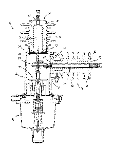
the switchgear that
increase the external creep distance. The single epoxy form also protects
against environment
elements.
SUMMARY
[0003] There are many issues, however, related to integrated switchgear.
First, over-molding
the switchgear as one part poses manufacturing challenges. In particular,
molding over multiple
components increases the risk of forming voids. Voids reduce electrical
integrity by creating air
pockets that may become charged. Voids can lead to coronal discharge and
voltage stress that
shortens the life of the switchgear.
[0004] In addition, when all of the components are tied together in one
integrated module,
the complexity of the switchgear is increased. For example, if an area within
the switchgear is
not over-molded properly, the entire switchgear may be unusable. The over-
molding also limits
the flexibility of the switchgear design. For example, if switchgear is needed
that has specific
1
CA 02849012 2014-03-17
WO 2013/058864 PCT/US2012/050813
requirements (e.g., voltage rating, sensor requirements, etc.), a completely
new design is needed
for the integrated switchgear even if just one component is changed.
[0005] Also, integrated switchgear is typically grounded and connected to a
metal taffl( or
housing assembly that holds operating mechanisms for the switchgear. The creep
distance of the
switchgear, however, is measured from the high voltage areas of the switchgear
to the metal
housing assembly. Therefore, the size of the switchgear must be designed to
allow for the proper
creep distance between the metal housing assembly and the high voltage areas.
In general, this
requires that the switchgear be larger to provide a proper creep distance.
[0006] Similarly, integrated switchgear also provides an area for the
operating rod to
function while providing an internal creep distance to the contact-moving
mechanism. Without
space to place skirts, the creep distance needed increases the height
requirements of the
switchgear. The operating rod also defines a creep distance over its surface
to the contact-
moving mechanism. To increase this creep distance, horizontal ribs are
sometimes placed along
the operating rod. However, adding these ribs often increases the height of
the switchgear.
[0007] As described above, the integrated switchgear includes a vacuum
interrupter. A
vacuum interrupter includes a ceramic bottle with two contacts vacuum-sealed
inside the bottle.
Fault interruption is performed in the vacuum. However, the contacts must have
enough holding
force so that the contacts do not weld together during a short circuit
interruption. The need for a
strong holding force creates challenges for the design of the contact-moving
mechanism that
operates the vacuum interrupter, which leads to complicated and expensive
mechanism design.
Additionally, to achieve a high mechanical life, a dampening system is used,
which adds cost and
complexity to the switchgear.
[0008] When a current transformer is included in the switchgear, it can be
molded into the
single-form epoxy of the integrated switchgear or can be externally mounted on
the epoxy.
Typically, wires are then attached between the current transformer and
monitoring equipment.
However, attaching external wires to the current transformer creates
additional manufacturing
challenges during final assembly of the switchgear.
2
CA 02849012 2014-03-17
WO 2013/058864 PCT/US2012/050813
[0009] Accordingly, embodiments of the invention provide non-integrated
switchgear that is,
in general, lower-cost and easier-to-manufacture and increases design
flexibility, reduces
production scrap, and improves serviceability. For example, a modular design
can be used that
reduces manufacturing challenges (e.g., risk of void formation) and increases
design flexibility.
In addition or alternatively, the housing assembly can be separately molded
from the vacuum
interrupter and source conductor. A plastic housing assembly can then be used
that provides
more external over surface distance from line to ground. The housing assembly
can house the
operating rod and provide the needed internal electrical creep distance. In
some constructions,
the housing assembly can include internal skirts to provide additional creep
distance. Also, the
operating rod can include vertical skirts to minimize the overall height of
the switchgear while
maximizing internal creep distance. Furthermore, a flexible conductor that
connects in series
with the vacuum interrupter can be used to provide more holding force for the
vacuum
interrupter during current interruptions. The flexible conductor, therefore,
can allow for lighter
and less expensive mechanisms and can provide dampening to increase the
mechanical life of the
switchgear. In addition, a current transformer can be molded into a portion of
the switchgear and
can include a molded connector to simplify wiring assembly.
[0010] In one construction, the invention provides modular switchgear. The
modular
switchgear includes a vacuum interrupter assembly, a source conductor
assembly, and a housing
assembly. The vacuum interrupter assembly has a first end and a second end and
includes a
bushing, a vacuum interrupter including a movable contact and a stationary
contact and at least
partially molded within the bushing, and a fitting positioned adjacent to the
second end. The
source conductor assembly has a first end and a second end and includes a
bushing, a source
conductor molded within the bushing, and a fitting positioned adjacent the
second end. The
housing assembly includes a housing defining a chamber, a drive shaft
positioned within the
chamber and configured to interact with the movable contact included in the
vacuum interrupter,
a conductor positioned within the chamber and configured to electrically
couple the vacuum
interrupter and the source conductor, a first receptacle for receiving the
fitting of the vacuum
interrupter assembly, and a second receptacle for receiving the fitting of the
source conductor
assembly. The vacuum interrupter assembly, the source conductor assembly, and
the housing
assembly are coupled without molding the assemblies within a common housing.
3
CA 02849012 2014-03-17
WO 2013/058864 PCT/US2012/050813
[0011] In another construction, the invention provides a method of
manufacturing
switchgear. The method includes providing a vacuum interrupter assembly
including a vacuum
interrupter molded within a bushing and including a fitting, the vacuum
interrupter including a
movable contact and a stationary contact; providing a source conductor
assembly including a
source conductor molded within a bushing and including a fitting; and
providing a housing
assembly including a drive shaft configured to couple to the movable contact,
a conductor
configured to electrically couple the vacuum interrupter and the source
conductor, a first
receptacle for receiving the fitting of the vacuum interrupter assembly, and a
second receptacle
for receiving the fitting of the source conductor assembly. The method also
includes coupling
the vacuum interrupter assembly to the housing assembly using the fitting of
the vacuum
interrupter assembly and the first receptacle without molding the vacuum
interrupter assembly
and the housing assembly within a common housing and coupling the source
conductor assembly
to the housing assembly using the fitting of the source conductor assembly and
the second
receptacle without molding the source conductor assembly and the housing
assembly within a
common housing.
[0012] In still another construction, the invention provides a vacuum
interrupter assembly for
modular switchgear. The vacuum interrupter assembly has a first end and second
end and
includes a bushing, a vacuum interrupter having a movable contact and a
stationary contact and
molded within the bushing, and a fitting positioned adjacent to the second end
configured to
couple the vacuum interrupter assembly to a receptacle on a housing assembly.
The housing
assembly includes a drive shaft configured to interact with the movable
contact and a conductor
configured to electrically couple the vacuum interrupter and a source
conductor. The vacuum
interrupter assembly is coupled to the housing assembly without molding the
vacuum interrupter
assembly and the housing assembly in a common housing.
[0013] In yet another construction, the invention provides a source
conductor assembly for
modular switchgear. The source conductor assembly has a first end and second
end and includes
a bushing, a source conductor molded within the bushing, and a fitting
positioned adjacent the
second end configured to couple the source conductor assembly to a receptacle
on a housing
assembly, the housing assembly including a drive shaft configured to interact
with a vacuum
interrupter and a conductor configured to electrically couple the source
conductor and the
4
CA 02849012 2014-03-17
WO 2013/058864 PCT/US2012/050813
vacuum interrupter. The source conductor assembly is coupled to the operating
housing without
molding the source conductor assembly and the housing assembly in a common
housing.
[0014] Other aspects of the invention will become apparent by consideration
of the detailed
description and accompanying drawings.
BRIEF DESCRIPTION OF THE DRAWINGS
[0015] FIG. 1 is a perspective view of modular switchgear according to one
embodiment of
the invention.
[0016] FIG. 2 is a cross-sectional view of the modular switchgear of FIG.
1.
[0017] FIG. 3 is a cross-sectional view of a vacuum interrupter of the
modular switchgear of
FIG. 1.
[0018] FIG. 4 is a cross-sectional view of a source conductor of the
modular switchgear of
FIG. 1.
[0019] FIG. 5 is a cross-sectional view of a housing assembly of the
modular switchgear of
FIG. 1.
[0020] FIG. 6 is a perspective view of a flexible conductor of the modular
switchgear of FIG.
1.
[0021] FIG. 7 is a cross-sectional view of the flexible conductor of FIG.
6.
[0022] FIG. 8 is a perspective view of the flexible conductor of FIG. 6
illustrating repulsion
forces acting on the conductor.
[0023] FIG. 9 is a perspective view of the flexible conductor FIG. 6
illustrating the conductor
acting as a damper.
[0024] FIG. 10 is a perspective view of a connector for a current
transformer of the modular
switchgear of FIG. 1.
CA 02849012 2014-03-17
WO 2013/058864 PCT/US2012/050813
[0025] FIG. 11 is a cross-sectional view of the connector of FIG. 10.
DETAILED DESCRIPTION
[0026] Before any embodiments of the invention are explained in detail, it
is to be
understood that the invention is not limited in its application to the details
of construction and the
arrangement of components set forth in the following description or
illustrated in the following
drawings. The invention is capable of other embodiments and of being practiced
or of being
carried out in various ways.
[0027] FIGS. 1 and 2 illustrate modular switchgear 30 according to one
embodiment of the
invention. The modular switchgear 30 includes a housing assembly 32, a vacuum
interrupter
("VI") assembly 34, and a source conductor assembly 36. The housing assembly
32 includes a
first receptacle 38 for receiving the VI assembly 34 and a second receptacle
40 for receiving the
source conductor assembly 36. The VI assembly 34 has a first end 42 and a
second end 44 and
includes a bushing 46 (see FIGS. 2 and 3). The bushing 46 is constructed from
an insulating
material, such as epoxy, that forms a solid dielectric. For example, the
bushing 46 can be
constructed from a silicone or cycloaliphatic epoxy or a fiberglass molding
compound. The
bushing 46 withstands heavily polluted environments and serves as a dielectric
material for the
switchgear 30. As shown in FIG. 3, the bushing 46 includes skirts 48 along the
outer perimeter.
[0028] The VI assembly 34 also includes a VI 50 at least partially molded
within the bushing
46. The VI 50 includes a movable contact and a stationary contact. The movable
contact is
movable to establish or break contact with the stationary contact. Therefore,
the movable contact
can be moved to establish or break a current path through the switchgear 30.
[0029] The VI assembly 34 also includes a fitting 52 positioned adjacent to
the second end
38. The first receptacle 38 of the housing assembly 32 receives the fitting
52. For example, as
shown in FIG. 3, the fitting 52 and the first receptacle 38 include mating
threads that allow the
VI assembly 34 to be screwed into the housing assembly 32. A gasket 54 is
placed between at
least a portion of the fitting 52 and the first receptacle 38 and is
compressed when the VI
assembly 34 is coupled to the housing assembly 32. The gasket 54 prevents
moisture and other
contaminants from collecting within the fitting 52 and the first receptacle 38
and entering the VI
6
CA 02849012 2014-03-17
WO 2013/058864 PCT/US2012/050813
assembly 34 or the housing assembly 32. The fitting 52 and the first
receptacle 38 can also be
configured to form other types of mechanical couplings between the housing
assembly 32 and
the VI assembly 34, such as a snap-fit coupling, a friction coupling, or an
adhesive coupling.
[0030] The source conductor assembly 36 is also coupled to the housing
assembly 32. As
shown in FIG. 4, the source conductor assembly 36 has a first end 60 and a
second end 62 and
includes a bushing 64. The bushing 64 is constructed from an insulating
material, such as epoxy,
that forms a solid dielectric. The bushing 64 also includes skirts 66 along
the outer perimeter. It
should be understood that the bushing 64 can be constructed from the same type
of insulating
material as the bushing 46 or can be different to provide different insulation
properties. The
source conductor assembly 36 also includes a source conductor 68 at least
partially molded
within the bushing 64. The source conductor 68 is electrically coupled to a
high-power system
(not shown) and provides a current path from the VI 50 to the high-power
system.
[0031] In addition, the source conductor assembly 36 includes a sensor
assembly 70. The
sensor assembly 70 can include a current transformer, a voltage sensor, or
both. As described in
further detail below with respect to FIGS. 10-11, the source conductor
assembly 36 can also
include a connector 72. The connector 72 is coupled to the sensor assembly 70
and includes a
portion that is exposed outside the bushing 64. The exposed portion of the
connector 72 is used
to connect the sensor assembly 70 to external equipment, such as external
monitoring equipment.
[0032] The source conductor assembly 36 also includes a fitting 74
positioned adjacent to the
second end 62. The second receptacle 40 of the housing assembly 32 receives
the fitting 74. For
example, as shown in FIG. 4, the fitting 74 and the second receptacle 40
include mating threads
that allow the source conductor assembly 36 to be screwed into the housing
assembly 32. A
gasket 76 is placed between at least a portion of the fitting 74 and the
second receptacle 40 and is
compressed when the source conductor assembly 36 is coupled to the housing
assembly 32. The
gasket 76 prevents moisture and other contaminants from collecting within the
fitting 74 and the
second receptacle 40 and entering the source conductor assembly 36 or the
housing assembly 32.
The fitting 74 and the second receptacle 40 can also be configured to form
other types of
mechanical couplings between the housing assembly 32 and the source conductor
assembly 36,
such as a snap-fit coupling, a friction coupling, or an adhesive coupling.
7
CA 02849012 2014-03-17
WO 2013/058864 PCT/US2012/050813
[0033] As shown in FIG. 5, the housing assembly 32 includes a housing 80
that defines a
chamber 82. In some embodiments, the first receptacle 38 and the second
receptacle 40 can be
molded in the housing 80. In other embodiments, the first and second
receptacles 38, 40 can be
coupled to the housing 80. The housing 80 can be constructed from a plastic
material that can
withstand high voltage in environmentally polluted areas. Using a plastic
material rather than a
metal material for the housing assembly 32 allows the housing assembly 32 to
be included in
creep distance measurements. Therefore, the overall size of the switchgear 30
can be reduced.
[0034] The housing assembly 32 includes a drive shaft 84, such as a rod,
which is positioned
within the chamber 82. The drive shaft 84 interacts with the VI 50 included in
the VI assembly
34. In particular, the fitting 52 included in the VI assembly 34 is positioned
adjacent an opening
in the bushing 46 that allows the drive shaft 84 to access and interact with
the movable contact of
the VI 50. Similarly, the first receptacle 38 is positioned adjacent an
opening in the housing
assembly 32 that allows the drive shaft 84 to be coupled to the VI 50.
[0035] The housing assembly 32 also houses a flexible conductor 86, which
is also
positioned within the chamber 82 defined by the housing 80. The flexible
conductor 86
electrically couples the VI 50 and the source conductor 68. As described in
more detail with
respect to FIGS. 5-7, the housing assembly 32 can also include other
components. In addition, as
shown in FIGS. 1 and 2, the housing assembly 32 is mounted on a base 88 that
houses additional
components of the switchgear 30. For example, the base 88 can house an
electromagnetic
actuator mechanism, a latching mechanism, and a motion control circuit.
[0036] Therefore, as described above, the VI 50 and the source conductor 68
are each
molded in separate bushings and are not over-molded within a common housing.
Rather, the
separately molded VI 50 and source conductor 68 are coupled to the housing
assembly 32, which
houses the drive shaft 84 and the flexible conductor 86, using the fittings
52, 74 and receptacles
38, 40. This modularity provides manufacturing and design flexibility. For
example, using the
modular VI assembly 34 and source conductor assembly 36 allows a similar
housing assembly
32 to be used for switchgear with different voltage ratings, VI ratings,
current transformer
requirements, etc. In particular, modular VI assemblies 34 can be created with
different VI
ratings but with a similar fitting 52 that mates with the first receptacle 38
on the housing
8
CA 02849012 2014-03-17
WO 2013/058864 PCT/US2012/050813
assembly 32. This allows the same housing assembly 32 to be used with
different VI assemblies
34 (e.g., with different VIs 50). Similarly, modular source conductor
assemblies 36 can be
created with different source conductors 68, sensor assemblies 70, or both but
with a similar
fitting 74 that mates with the second receptacle 40 on the housing assembly
32. Also, because
the VI 50, source conductor 68, and drive shaft 84 and flexible conductor 86
are not over-molded
in a common housing, such as a single epoxy form, any voids forming on
individual components
does not make the entire switchgear unusable or unsafe. Rather, because the
components are
separately molded, a component with a void can be replaced and the remaining
components can
be reused. Furthermore, in some embodiments, the modular VI assembly 34 and/or
source
conductor assembly 36 are removably coupled to the housing assembly 32, which
allows them to
be removed and replaced for maintenance purposes or design changes. Similarly,
the modular
assemblies 34 and 36 can be removed from one housing assembly 32 and installed
on a new
housing assembly 32 for maintenance or design purposes.
[0037] Accordingly, to manufacture the switchgear 30, the VI assembly 34
and the source
conductor assembly 36 are created by separately molding the components. For
example, to
create the VI assembly 34, the VI 50 is placed within a mold and the mold is
at least partially
filled with an insulating material, such as one of an epoxy or molding
compound, which forms
the bushing 46 with the skirts 48 and the fitting 52. Similarly, to create the
source conductor
assembly 36, the source conductor 68 and sensor assembly 70 (and, optionally,
the connector 72)
are placed within a mold and the mold is at least partially filled with an
insulating material,
which forms the bushing 64 with the skirts 66 and the fitting 74.
[0038] Once the assemblies 34 and 36 are provided, the housing assembly 32
is also
provided. Initially, the housing 80 of the housing assembly 32 can be formed
using injection
molding or other plastic-forming techniques. The housing 80 defines the
chamber 82, where the
drive shaft 84 and the flexible conductor 86 are positioned. The housing 80
also defines the first
receptacle 38 and the second receptacle 40.
[0039] After the housing assembly 32 is provided, the VI assembly 34 is
coupled to the
housing assembly 32 using the fitting 52 of the VI assembly 34 and the first
receptacle 38 of the
housing assembly 32. As described above, coupling the VI assembly 34 to the
housing assembly
9
CA 02849012 2014-03-17
WO 2013/058864 PCT/US2012/050813
32 can include screwing the fitting 52 into the first receptacle 38. As also
described above, the
gasket 54 can be placed between the fitting 52 and the first receptacle 38 to
provide a secure
coupling.
[0040] The source conductor assembly 36 is also coupled to the housing
assembly 32 using
the fitting 74 of the source conductor assembly 36 and the second receptacle
40 of the housing
assembly 32. Again, as described above, coupling the source conductor assembly
36 to the
housing assembly 32 can include screwing the fitting 74 into the second
receptacle 40. A gasket
76 can be placed between the fitting 74 and the second receptacle 40 to
provide a secure
coupling. The housing assembly 32 is also mounted on the base 88, which houses
additional
components for the switchgear 30. With the VI assembly 34 and the source
conductor assembly
36 coupled to the housing assembly 32 and the housing assembly 32 mounted on
the base 88, the
switchgear 30 can be installed in a high-power distribution system.
[0041] FIG. 5 illustrates the housing assembly 32 and the components
contained in the
housing assembly 32 in more detail. In particular, as shown in FIG. 5, the
housing assembly 32
includes the drive shaft 84, the flexible conductor 86, and a creep extender
90 positioned within
the chamber 82 defined by the housing 80. The creep extender 90 includes a
first portion 90a
that is coupled to the housing assembly 32 and/or the base 88. The creep
extender 90 also
includes a second portion 90b that is positioned approximately perpendicular
to the first portion
90a and forms vertical skirts 92. The vertical skirts 92 mimic or correspond
to vertical skirts 94
on the drive shaft 84 such that the skirts 92 of the creep extender 90 extend
between the skirts 94
on the drive shaft 84 without contacting the skirts 94. Due to this
positioning of the skirts 92 and
94, internal creep distance is increased without adding to the overall height
of the switchgear 30.
[0042] As also shown in FIG. 5, the drive shaft 84 is coupled to a movable
contact 96 of the
VI 50 via a spring assembly 98 and a stud 100. The drive shaft 84 moves
vertically within the
chamber 82 with the stroke of the VI 50 but, as noted above, does not come
into contact with the
creep extender 90, which maintains the needed creep distance.
[0043] FIGS. 6 and 7 illustrate the flexible conductor 86 in more detail.
As shown in FIG. 6,
the flexible conductor 86 includes a loop portion 102, which is flexible. The
loop portion 102
includes a clearance hole or slot 106 on one side of the loop 102 and a hole
104 on the other side
CA 02849012 2014-03-17
WO 2013/058864 PCT/US2012/050813
of the loop 102. The flexible conductor 86 is bolted with the movable contact
96 of the VI 50
via the hole 104. A remaining portion 108 of the flexible conductor 86 is also
attached to a bus
bar 110 that is rigidly attached to the source conductor 68. A clearance hole
112 in the bus bar
110 allows an insulating tube 114 to freely move up and down. The insulating
tube 114 is fixed
between two insulating washers 116 and over the metal stud 100. The insulating
tube 114
prevents electricity conducting from the bus bar 110 and the flexible
conductor 86 to pass
through the metal stud 100. The insulating washers 116 and the insulating tube
114 provide
insulation between the flexible conductor 86 and the metal stud 100, so that
all current flows
through the loop 102.
[0044] Under normal operations, the flexible conductor 86 is connected in
series with the
circuit of the switchgear 30. Once the circuit is closed, current flows in and
out of the bus bar
110 and the source conductor 68 and also through the flexible conductor 86.
The flexible
conductor 86 and the bus bar 110 form two reverse loops or paths. A full loop
or path is between
the bus bar 110 and the entire loop portion 102 of the flexible conductor 86.
A half loop or path
is between the loop portion 102 of the flexible conductor 86 and the remainder
of the assembly
86. The two reverse loops generate repulsion forces due to the electromagnetic
field effects
generated by the current flowing through the loops, as shown in FIG. 8. These
repulsion forces
are added to the contact holding force between the movable contact 96 and the
stationary contact
of the VI 50. Therefore, the mechanical holding force on the movable contact
96 of the VI 50
can be reduced.
[0045] In particular, the loop portion 102 causes repelling magnetic
forces. The closer the
faces of the loop portion 102 are to each other, the greater the forces. For
example, the repulsion
forces from the full loop acts on a washer (e.g., a Belleville washer) 122 and
a jam nut 120
because the bus bar 110 is fixed. This force is symmetric around the movable
contact 96 of the
VI 50. The repulsion force from the half loop acts directly on the movable
contact 96. The
repulsion force from a current reverse loop is inversely proportional to the
separation distance
between the two currents running in opposite directions. The smaller the
distance is, the higher
the repulsion force. The flexible conductor 86 provides a minimum distance to
the half loop
using the thin jam nut 120. For the full loop, the separation distance is
designed to be the stroke
11
CA 02849012 2014-03-17
WO 2013/058864 PCT/US2012/050813
of the VI 50. This design ensures not only a minimal distance for the full
loop, but also makes a
laminated flexible loop 102 act as a damper during an open circuit.
[0046] In particular, a laminated flexible loop 102 is typically thicker in
a free state than in a
compressed state (when the thickness is squeezed to its minimum). During
opening of the VI 50,
the movable contact 96 is pulled by opening springs to separate the contacts.
In this situation, as
shown in FIG. 9, the main portion of the flexible loop 102 flexes and moves
closer to the bus bar
110, which is fixed and static. As the flexible loop 102 is moving toward the
bus bar 110, the
outermost lamination touches the bus bar 110 first while the rest of the
lamination is squeezed to
its minimum thickness. Since the bus bar 110 is fixed, the lamination
compresses to the bus bar
110 as the metal stud 100 goes through the clearance hole 112 in the bus bar
110. Therefore, the
moving kinetic energy of the switchgear is gradually absorbed by squeezing the
laminated
flexible loop 102, which acts as a damper.
[0047] As noted above, the source conductor assembly 36 can include a
sensor assembly 70
(e.g., including a current transformer). The sensor assembly 70 can be molded
into the source
conductor assembly 36 and can be grounded via an internal ground wire. To
connect the sensor
assembly 70 to external equipment, a connector 72 can be coupled to the sensor
assembly 70.
FIG. 10 illustrates a connector 72 according to one embodiment of the
invention. The connector
72 is molded in the source conductor assembly 36 but includes a receptacle 130
that is exposed
outside the bushing 64 (see FIG. 11). The exposed receptacle 130 is used to
connect the sensor
assembly 70 to external equipment, such as external monitoring equipment.
[0048] Accordingly, the modular switchgear 30 allows for smaller, more
flexible, and more
cost-effective switchgear. Also, is should be understood that individual
features of the design
may be used separately and in various combinations. For example, the connector
72 with the
exposed receptacle 130 can be used with switchgear of another design where a
sensor is included
in the switchgear, such as integrated switchgear described in the background
section above.
Also, in some embodiments, a modular VI assembly 34 can be used without a
modular source
conductor assembly 36 or vice versa to provide various levels of flexibility
and modularity. For
example, if a modular VI assembly 34 is not used, the components included in
the VI assembly
34 can be housed within the housing assembly 32 or integrated with other
switchgear
12
CA 02849012 2014-03-17
WO 2013/058864 PCT/US2012/050813
components. Similarly, if a modular source conductor assembly 36 is not used,
the components
included in the source conductor assembly 36 can be housed within the housing
assembly 32 or
integrated with other switchgear components. Also, the modular bushings 34 and
36 can be used
without using a housing assembly 32 made of plastic and/or used without a
creep extender 90.
Similarly, the plastic housing assembly 32 and/or the creep extender 90 can be
used without one
or both of the modular assemblies 34, 36. Furthermore, the flexible conductor
86 described
above can be used in any type of switchgear and is not limited to being used
in the switchgear 30
described and illustrated above. Also, a non-flexible conductor 86 can be used
with the modular
assemblies 34, 36.
[0049] Various features and advantages of the invention are set forth in
the following claims.
13