Note : Les descriptions sont présentées dans la langue officielle dans laquelle elles ont été soumises.
CA 02849247 2014-03-19
WO 2013/043515
PCT/US2012/055669
HIGH DENSITY STORAGE FACILITY
RELATED APPLICATIONS
[0001] This Application claims priority to U.S. Application No.
13/241,326 filed on
23 September 2011, which is a continuation-in-part application of U.S.
Application No.
12/464,745, filed on 12 May 2009, and of U.S. Provisional Application Numbers
61/514,057,
filed on 2 August 2011 and 61/127346, filed on 12 May 2008, all of which are
incorporated
herein by reference.
BACKGROUND
[0002] The present application relates to high density storage
facilities, and more
particularly to high density storage facilities for storing intermodal
containers, boats and
other large items.
[0003] Despite advances in building materials, material handling
vehicles, and
techniques, there is still a need for storage facilities for large sized
objects such as intermodal
containers, boats, cars, furniture and the like. Such facilities should
provide mechanisms for
obtaining ready and efficient access to the stored objects, as well as optimal
use of storage
space.
[0004] For example, conventional boat storage facilities include a large
building with
racks aligned along the walls and a large unoccupied floor space. This results
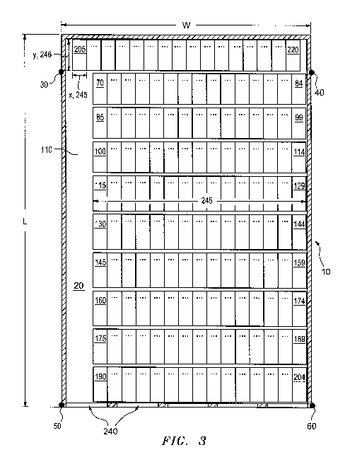
in a large
amount of unused space, as depicted in FIG. 1 for building B with corners Cl,
C2, C3 and
C4. Two access entryways Al and A2 are defined at an end of building B to
enable a fork-
lift truck to place and withdraw large items such as boats from the three
stationary, fixed
storage racks R1, R2 and Rs.
[0005] A more efficient system is depicted in FIG. 2 based on U.S. Patent
No.
5,140,787 by the present inventor for facility F having building corners C1-C4
and a
stationary rack Si extending along length L of facility F. Multiple access
doors Al, A2, A3
and A4 are provided along the length L. One or more of four movable elongated
rectangular
racks R1, R2, R3 and R4 can be rolled along length L to expose a selected rack
row to a fork-
lift truck entering through one of access doors Al-A4. However, many square
feet of space
must still be left open to provide turning and maneuvering room for the fork-
lift truck, and
1
CA 02849247 2014-03-19
WO 2013/043515
PCT/US2012/055669
multiple access doors must be provided along the side of an elongated
building.
[0006] Container terminals for storing and retrieving intermodal
containers exhibit
similar problems. Conventional facilities consume large areas of valuable
seaport acreage.
Because conventional facilities may use numerous aisles and provide wide
spaces between
intermodal containers, and because such containers are generally randomly
placed and widely
spaced, many terminal operators have difficulty in controlling the storage,
retrieval and
delivery of the containers. This often results in time consuming and costly
repositioning and
searching operations for displaced containers.
[0007] Therefore, a need exists for a high density storage facility which
provides
ready and efficient access to the space within the facility where items may be
stored.
SUMMARY OF THE INVENTION
[0008] An object of the present invention is to provide a highly modular
and
adaptable storage system which increases the storage capacity of a given area.
[0009] This invention features a high density storage facility including
a plurality of
rows of independently movable carriage racks, each row having a plurality of
the
independently movable carriage racks. Each carriage rack has a height, a
length and a width,
and defines a plurality of tiers, each tier defining at least one storage
slot, the slots extending
substantially the length of the carriage racks and being substantially open
and accessible for
inserting and removing objects into and from the width ends of the carriage
racks. The
carriage racks are disposed within the floor area and are independently
movable along the
floor in a direction consistent with the width of the floor area. Preferably,
the carriage racks
are arranged in the rows within the floor area with the lengthwise sides of
the carriage racks
being arranged substantially parallel to the lengthwise sides of the floor
area.
[0010] In some embodiments, the carriages include a mechanism for moving
the
racks, such as at least one independently controllable motor to drivably move
each carriage
rack across at least a portion of the width of the floor area. The carriage
racks may further be
coupled and uncoupled along the width of the enclosed storage area for
providing access to
the width ends of the racks from the doors. The carriage racks may be
connected and
disconnected along their lengthwise sides, forming rows which are movable in a
widthwise
2
CA 02849247 2014-03-19
WO 2013/043515
PCT/US2012/055669
direction along the storage area. Tracks for rolling the carriage racks may
extend along the
width of the storage area. According to one embodiment, the carriages include
motor
mechanisms for moving the racks across a portion of the storage area. For some
applications,
it may be useful to include as many rows of carriage racks as will fit along
the width of the
storage area.
[0011] The number of carriage racks may be chosen such as to leave a
portion of the
floor area unoccupied, of a size sufficient to provide access from optional
doors to the width
ends of the carriage racks upon selective movement of carriage racks within
the rows along
the width of the storage area. According to one embodiment, at least one door
is selectively
disposed along the wall of the building so as to provide access to the
unoccupied floor area
upon selective movement of one or more of the carriage racks in the rows of
carriage racks
along the width of the storage area. The unoccupied floor area may be selected
to be of such
size as to accommodate manipulation of the objects within the unoccupied floor
area for
insertion into the slots. The unoccupied floor area may further be selected to
be of such a size
as to be accessible to the doors upon movement of one or more of the carriage
racks in the
rows of carriage racks along the width of the floor area. A row of racks may
include a series
of spaced vertical supports interconnected by a series of spaced horizontal
supports. The
horizontal supports may be adjustable in position along the height of the
vertical supports.
[0012] The facility may include a row of stationary racks arranged along
at least one
wall, the stationary racks having a certain length, width and height and being
divided from
top to bottom into storage slots. The slots may extend the length of the
racks, and may be
open and accessible from a width end for inserting and removing objects. The
width ends of
the racks may face the storage area.
BRIEF DESCRIPTION OF THE DRAWINGS
[0013] In the accompanying drawings:
[0014] FIG. 1 depicts a conventional boat or other large object storage
facility;
[0015] FIG. 2 depicts a known floor plan as taught in U.S. Patent No.
5,140,787;
[0016] FIGS. 3-8 depict an exemplary embodiment of a floor plan and
operation of a
storage facility utilizing carriage racks according to the present invention;
[0017] FIG. 9 is a schematic view of a pair of carriage racks coupled
together and
3
CA 02849247 2014-03-19
WO 2013/043515
PCT/US2012/055669
mounted on wheels set in parallel tracks for rolling the carriage racks along
the floor.
[0018] FIG. 10A depicts an electromagnetic coupling system suitable for
use with
illustrative embodiments of the present invention;
[0019] FIG. 10B depicts an exemplary rack, mounted on an electromagnetic
carriage
suitable for use with a maglev system according to exemplary embodiments;
[0020] FIG. 10C depicts an exemplary rack, mounted on a wheeled carriage
suitable
for use with a maglev system according to exemplary embodiments;
[0021] FIG. 11 is a top view of a narrow storage area converted into a
high density
storage facility according to the present invention;
[0022] FIG. 12 is a top schematic view of a storage facility similar to
FIG. 2 showing
six rectangular racks and a wide fork-lift truck aisle area;
[0023] FIG. 13 is a top view showing how additional storage slots can be
provided
according to the present invention for the facility of FIG. 12 after a
retrofit;
[0024] FIGS. 14 and 15 are schematic top views of another high-density
storage
facility according to the present invention;
[0025] FIGS. 16A-16D are schematic side elevational views of different
carriage
rack storage configurations according to the present invention;
[0026] FIGS. 17A-1 and 17A-2 are top left and right views, respectively,
sharing
match line ML-ML, of another high density storage facility according to the
present
invention;
[0027] FIGS. 18A-1 and 18A-2 are side elevational left and right views,
respectively,
sharing match line ML-ML, of the stationary racks of FIGS 17A-1 and 17A-2
aligned with
the length of the storage facility;
[0028] FIG. 19 is an end elevational view of the width and height of the
storage
facility of FIGS. 17A-1 and 17A-2;
[0029] FIGS. 20A-1, 20-A-2, 20B, 20C and 20D are schematic side
elevational
views of different carriage configurations A, B, C and D of FIGS. 17A-1 and
17A-2;
[0030] FIG. 21 depicts an exemplary carriage rack, mounted on a wheeled
carriage
suitable for use with an intermodal container according to exemplary
embodiments; and
[0031] FIG. 22 depicts an exemplary overhead view of fixed racks and
carriage racks
configured for use with an intermodal container according to exemplary
embodiments.
4
CA 02849247 2014-03-19
WO 2013/043515
PCT/US2012/055669
DETAILED DESCRIPTION
[0032] This invention may be accomplished by a high density storage
facility
including a plurality of rows of independently movable carriage racks, each
row having a
plurality of the independently movable carriage racks. Each carriage rack has
a height, a
length and a width, and defines a plurality of tiers, each tier defining at
least one storage slot,
the slots extending substantially the length of the carriage racks and being
substantially open
and accessible for inserting and removing objects into and from the width ends
of the
carriage racks. The carriage racks are disposed within the floor area and are
independently,
selectively movable as desired along the floor in a direction consistent with
the width of the
floor area to provide access to a chosen storage slot within a determined row.
Preferably, the
carriage racks are arranged in the rows within the floor area with the
lengthwise sides of the
carriage racks being arranged substantially parallel to the lengthwise sides
of the floor area.
The following description sets forth illustrative embodiments of the present
invention, it
being understood that other embodiments not specifically described herein are
encompassed
by the present invention.
[0033] FIGS.
3-8 show the overall floor plan of an illustrative storage facility 10. In
one embodiment, a floor area 110 which is defined by lines connecting points
30, 40, 50, 60
is provided. The floor area may be in the shape of a polygon, for example, a
rectangle or a
square. The floor area includes a width, designated "W" in Figure 3, and a
length, designated
"L" in Figure 3. The direction indicated by the double-arrows associated with
the width W
in Figure 3 is referred to herein as the "widthwise direction," and the
direction indicated by
the double arrows associated with the length L in Figure 3 is referred to
herein as the
"lengthwise direction.
[0034] As
depicted in Figures 3 and 4, an exemplary embodiment has a floor
area of 275 feet by 425 feet, which allows a number of suitably placed
carriage racks to be
accessed. One having ordinary skill in the art will understand that the floor
area may be
greater or smaller than that shown, depending on the application. More or
fewer carriage
racks may be employed as needed. The carriage racks and the fixed racks each
have a length
and a width, as indicated by length "Y" 246 and width "X" 245 of fixed rack
205 in at least
Figure 3. While the length and width have been described with relation to
fixed rack 205,
each carriage rack as discussed below has a length "Y" 246 and width "X" 245.
Each fixed
rack has a length and a width along the same axes defined in relation to fixed
rack 205.
CA 02849247 2014-03-19
WO 2013/043515
PCT/US2012/055669
Likewise, each carriage rack has a length and a width along the same axes
defined in relation
to other carriage racks in the same row and adjacent rows. The lengthwise
direction of the
fixed racks and the carriage racks may correspond to the lengthwise direction
of the floor
area, and the widthwise direction of the rack may correspond to the widthwise
direction of
the floor area.
[0035] A carriage rack is a movable rack, which may include means
for
locomotion integrated into the frame of the carriage, or may be mounted on a
movable
carriage structure. A plurality of movable carriage racks 70-84, 85-99, 100-
114, 115-129,
130-144, 145-159, 160-174, 175-189, and 190-204 are arranged as shown in rows
within
floor area 110, each row including a number of individual racks. Depending on
the
application, as many or as few carriage racks as needed may be selected. In
the illustrative
embodiment depicted in FIG. 4, each row includes 15 carriage racks. In this
illustrative
embodiment, a selected width of the area 110 is filled with carriage racks,
for purposes of
maximum space utilization. In other embodiments, concerns other than space
utilization may
call for a different configuration or a different number of racks.
[0036] In the illustrative embodiment, each row of carriage racks
70-84, 84-
99, 100-114, 115-129, 130-144, 145-159, 160-174, 175-189, and 190-204 is
movable
widthwise along the area 110. The rows may be mounted on rotatable rollers or
wheels, such
as wheels 11, FIG. 9, which are in turn mounted in guides, slots or rails such
as tracks 12
which extend a selected width of area 110, FIG. 3. Alternatively, the rows may
be mounted
using any other system that facilitates the movement of the carriage racks,
such as a magnetic
levitation system, an air levitation system that allows movement of the rows
of racks, or a
system of wheels without a track, the system of wheels can include one or more
tires. In the
illustrative embodiment, wheels 11, FIG. 9, are mounted at the bottom of both
widthwise
sides of each carriage rack 302, 304 and a series of spaced parallel tracks 12
are provided
along the width of the area 110 to coincide with the direction of
displacement. It is not a
limitation of the invention that consecutive even reference numbers 302 and
304 are utilized
in FIG. 9, while consecutive odd and even numbers are utilized in FIGS. 3-8.
In some
embodiments, each carriage rack in each row is movable independent of other
carriage racks
in the row. For example, in some embodiments carriage rack 70 moves
independently of
carriage racks 71-84. In some embodiments two or more racks are coupled or
formed
together to move in unison. For example, in some embodiments carriage racks 70
and 71
6
CA 02849247 2014-03-19
WO 2013/043515
PCT/US2012/055669
move in unison.
[0037] In the embodiments shown in FIGS. 3-8, all of the carriage
racks in
each row have the same length and width, although the lengths and widths of
individual rows
of carriage racks may vary. In that case, the widthwise disposition of wheels
and
complementary tracks 12 should coincide with the lengths of each individual
carriage rack.
The tracks may extend the width of area 110, i.e. between the line connecting
points (30, 60)
and points (40, 50). Alternatively, the tracks may extend a different
distance, depending on
the particular application. In some embodiments the widths 245, FIG. 10B, of
individual
carriage racks may vary from row to row or in a row. In some embodiments the
lengths 246
of carriage racks may vary from row to row or in a row.
[0038] Each carriage rack may be divided into slots 14, FIG. 9,
from top to
bottom. In applications such as boat storage, one having ordinary skill in the
art will
appreciate that the total height of the slots may be determined by the
facility. However, the
size of the carriage racks may vary depending on the application.
[0039] In one embodiment, the carriages and racks are a unitary
structure
including a series of parallel vertically oriented supports 18 connected from
top to bottom by
a series of parallel horizontal 19 supports. Conventional mechanisms may be
provided for
adjusting a horizontal support up and down along the vertical supports 18. For
example, the
mechanisms may adjust the horizontal support in increments of, for example,
inches, or may
adjust the horizontal support in larger or smaller increments, depending on
the application.
In one embodiment, the vertical distance between successive horizontal
supports defines the
slot height and the horizontal distance between successive vertical supports
18 defines slot
width.
[0040] According to one embodiment, a series of doors 240, FIGS. 3-
8, are
disposed along one widthwise wall of the facility. An unoccupied and
changeable service
and loading area 20 may be provided, the size of which may be selected based
on a number
of factors. Such factors may include where doors 240 are disposed along the
outer wall.
[0041] When carriage racks in a row 70-84, 85-99,100-114,115-
129,130-
144,145-159,160-174,175-189, and 190-204 are appropriately moved along the
floor area
110, enough floor area 20 may be left unoccupied so as to enable the user to
gain access to
7
CA 02849247 2014-03-19
WO 2013/043515
PCT/US2012/055669
the width ends 245 of each row. As shown in FIGS. 3 -8, the unoccupied floor
area 20 may
be large enough relative to the displacement of doors 240 so as to enable a
user of the facility
to gain access to the width ends 245 of the carriage racks. This can be
accomplished by
moving one or more carriage racks sufficiently to enable a user to gain access
to the width
ends 245 of racks in a row through a door 240. Objects to be stored in the
slots may be
inserted via the width ends 245 of the carriage racks. In some embodiments,
objects to be
stored in the slots may be inserted via the length wise opening 246 of the
carriage racks.
[0042] As shown in FIGS. 3-8, a stationary row of racks 205-220
along the
doorless widthwise wall may be provided. This may allow for greater storage
utilization in
the facility. The width ends 245 of racks 205-220 may also be accessible
through at least one
door 240 by appropriate movement of carriage racks in rows 70-84, 85-99,100-
114,115-
129,130-144,145-159,160-174,175-189, and 190-204 of carriage racks along the
width of
area 10.
[0043] The size of the unoccupied floor area 20 may be selected
such that it is
large enough to allow the objects to be stored in the carriage racks and to be
manipulated into
the width ends 245 of the carriage racks. For example, the length and width of
the
unoccupied floor space 20 may be selected to be long enough and wide enough to
enable a
forklift to align itself parallel to the length of the carriage racks for
insertion and removal of
the boat(s) into and from the width ends 245 of the carriage racks. Likewise,
the size of the
unoccupied floor area 20 may be selected such that it is large enough to allow
the objects to
be stored in the carriage racks and to be manipulated into the length wise
opening 246 of the
carriage racks. For example, the length and width of the unoccupied floor
space 20 may be
selected to be long enough and wide enough to enable a forklift to align
itself perpendicular
to the length of the carriage racks for insertion and removal of an intermodal
container from
the length wise opening 246 of the carriage racks.
[0044] Figure 4 depicts unoccupied floor space 20 at the far left
of the floor
area 110. This configuration may facilitate, for example, access to the width
end 245 of rack
220. However, with reference to Figures 5-6, a user may desire to gain access
to the width
end 245 of carriage rack 104 to remove an object from the rack. According to
one
embodiment of the present invention, appropriate carriage racks may be shifted
in a
widthwise direction with respect to the floor area 110, as depicted in Figures
5-6. In Figure
8
CA 02849247 2014-03-19
WO 2013/043515
PCT/US2012/055669
6, the appropriate carriage racks have been shifted such that unoccupied floor
space 20
provides a passage to the width end 245 of carriage rack 104, allowing access
to carriage
rack 104, for example, by a forklift. In Figure 7, the carriage racks have
been further shifted
to provide a passage via unoccupied floor space 20 to the width end 245 of
carriage rack 136.
Similarly, in Figure 8, appropriate carriage racks have been shifted in order
to provide access
via unoccupied floor space 20 from the door to the width end of carriage rack
167.
[0045] In one embodiment, the lengths and widths of movable
carriage racks
70-84, 85-99,100-114,115-129,130-144,145-159,160-174,175-189 and 190-204 may
vary
among different movable rows provided within a facility 110. The facility 110
may be
provided with an unoccupied area 20 of at least a size sufficient to obtain
access through an
appropriate door 240 to all of the width ends 245 of the carriage racks. This
may be
accomplished, for example, upon appropriate widthwise movement of successive
rows of
carriage racks within a floor area defined by lines between points 30, 40, 50,
and 60. The
facility 10 may be provided with a stationary row of racks 205-220. These
stationary racks
may also have varying widths, or may be of the same width, and may be located
along a
doorless wall. The movable carriage racks 70-84, 85-99,100-114,115-129,130-
144,145-
159,160-174, 175-189, and 190-204 may be aligned such that their lengthwise
dimensions are
substantially parallel to the lengthwise dimension of area 110.
[0046] In some embodiments, it may be necessary or desirable to
access the
length ends of the carriage racks. For example, intermodal containers may be
stored in the
racks which must be lifted, for example by a forklift, from the length ends.
Accordingly, the
racks may be oriented so as to afford access to the length ends from the
doors.
[0047] In more detail, FIG. 9 depicts a schematic front view of a
pair of
illustrative coupled carriage racks 302 and 304 according to the present
invention. The racks
are divided into slots 14 by vertical supports 18 and by horizontal supports
19. A row of
carriage racks may extend across the width of a selected defined floor space
(e.g. between
points 30, 60 and 40, 50), or may extend across any width that is appropriate
to the particular
application. The movable coupled racks may be mounted on rollable, rotatable
wheels 11
which, in turn, may be mounted within complementary tracks 12 provided on the
floor
surface. In one embodiment, each axle A has at least one drive motor M to
provide
redundant systems to move the carriage racks.
9
CA 02849247 2014-03-19
WO 2013/043515
PCT/US2012/055669
[0048] The racks may alternatively be mounted on carriages. For
example,
FIG. 10B depicts an exemplary rack, mounted on an electromagnetic carriage
suitable for
use with a maglev system according to exemplary embodiments of the present
invention.
FIG. 10C depicts an exemplary rack, mounted on a wheeled carriage suitable for
use with a
maglev system according to exemplary embodiments of the present invention.
[0049] The carriage racks may be coupled along the lengthwise side,
the
widthwise side, or both. The carriage racks may be coupled using any suitable
coupling
method, such as by an electromagnetic coupling system, an electromotive
coupling system,
or a mechanical coupling system such as a system of hooks. For example, FIG.
10A depicts
an electromagnetic coupling system suitable for use with illustrative
embodiments of the
present invention, such as to join together the lengths 246 of two carriages.
[0050] In one embodiment, the rows of fixed racks 205-220, FIGS. 3-
8, may
be aligned such that their width ends 245 face the widthwise side of area 110
and are
substantially parallel thereto. The stationary racks may be smaller,
lengthwise or widthwise
or both, than the movable racks for purposes of ease of loading, unloading and
storage of
smaller objects. Alternatively, the stationary racks may be of the same size
as the movable
carriage racks, or larger, depending on the application.
[0051] In one embodiment, motor means may be provided to drive the
movable carriage racks in the rows of carriage racks along the lengths of area
110. Remote
control means for the motor means may be provided for access to the user
outside of area
110. These remote control means may be outside, such as on the outside
surfaces of the
walls in which access doors 240 are disposed. The user can thus drivably move
the carriage
racks remotely from outside areas 20, 110. Alternatively, the remote control
means may be
located inside, as appropriate to the application. The motor means may also be
controlled
locally.
[0052] FIG. 11 depicts a storage facility 400 according to the
present
invention nestled between walls 402 and 404 defining a narrow width W. For
this example,
width W is 35 feet and length L is 140 feet. Access for fork-lift trucks is
provided at end
406, where one or more access doors can be constructed. Row 408 has four 20-
feet long by
8-feet wide storage slots in a first tier, which is provided by four movable
carriage racks in
one construction and is a single stationary rack having four slots in another
construction.
CA 02849247 2014-03-19
WO 2013/043515
PCT/US2012/055669
Movable fork truck aisle 410, having a width of 11 feet for the carriage
positions shown in
FIG. 11, represents the open area needed within storage facility 400 to
manipulate movable
carriage racks in rows 412, 414, 416, 418 and 420 as needed to access a
selected storage slot.
Each row 412-420 is formed of three independently movable carriage racks which
move
substantially along width W between walls 402 and 404. In the illustrated
construction, each
row 412-420 has one carriage having a width of 8 feet, a second, middle
carriage having a
width of 7 feet, and a third carriage having a width of 8.5 feet. Carriage
racks in rows 412
and 414 have lengths of 20 feet while carriage racks in rows 416-420 have
lengths of 22 feet.
The movable carriage racks provide a total of fifteen storage slots on the
first tier to
accommodate 15 items of different sizes and lengths on the first tier, such as
different types
of boats. Adding a second tier to each carriage rack and the stationary rack
doubles the
storage slots to 38 items. Five tiers would handle at least 95 items, assuming
one storage slot
per tier; other storage slot per tier configurations are described below.
[0053] Storage facility 500, FIG. 12, is similar to facility F in
FIG. 2 as
described above in the Background and is also based on U.S. Patent No.
5,140,787 by the
present inventor. In this construction, facility 500 has an overall length L
of 200 feet and an
overall width W of 135 feet. A single stationary rack 502 extends along the
length L
defining fifteen stationary slots SS1-SS15 in a first tier. Facility 500
further includes six
movable rectangular racks 504, 506, 508, 510, 512, and 514 each defining a
number of
movable slots MS1-MS8, MS9-MS20, MS21-MS30, MS31-MS42, MS43-M552, and MS53-
MS62, respectively, with the width ends of the slots facing the width ends of
facility 500 and
facing the direction of movement indicated by arrows 520 and 521. In other
words, each
rectangular rack row of boats is moved "fore and aft" or "bow and stern"
relative to the
position of the boats in the rack rows. Facility F can handle up to 77 boats,
ranging in length
from twenty feet to thirty nine feet, on tier level 1. Having four levels of
tiers with similar
storage slots would provide a maximum capacity of 308 boats or similar items
for this
configuration of facility 500.
[0054] Facility 500 requires an open fork truck aisle space 522
having
dimensions of 95 feet, arrow 524, by 60 feet, arrow 526, for a total of 5,700
square feet of
open space, to accommodate movement in the length-wise direction, arrows 520
and 521, of
the six rectangular rack rows 504-514. Access doors must be provided along
length side 528.
[0055] By comparison, if independently movable carriage racks
according to
11
CA 02849247 2014-03-19
WO 2013/043515
PCT/US2012/055669
the present invention are installed, and rotated ninety degrees so that their
width ends face
side 528, an additional 20 boats can be added per tier as shown in FIG. 13 for
the area
bounded by arrow 524 of 95 feet and by arrow 526 of 60 feet. Installing four
levels of tiers
would increase the capacity by an additional 80 boats while still providing
access to
stationary storage slots in rack 502, FIG. 12, as needed. Movable carriage
rack rows 540,
542, 544, and 546 each have movable carriage racks MC1-MC5, MC6-MC10, MC11-
MC15,
and MC16-MC20, respectively. In this construction, carriage racks MC1-MC10
have
lengths of 20 feet each, carriage racks MC11-MC15 have lengths of 22 feet
each, and
carriage racks MC16-MC20 have lengths of 24 feet each. The widths of the
carriage racks
within each row are 8.5 feet, 8 feet, 8.5 feet, 8 feet, and 8.5 feet, with
fork truck aisle 548
having a width of only 18 feet. Boats on movable carriage racks according to
the present
invention would be selectively moved "beam-to-beam" or side-to-side throughout
facility
500 after a retrofit as taught herein. Alternatively, if a facility has an
independent,
unoccupied space bounded by the dimensions shown in FIG. 13, two additional
storage slots
can be added to row 540, per tier.
[0056] Storage facility 600 according to the present invention,
FIGS. 14 and
15, has a stationary rack 602 and seven rows 604, 606, 608, 610, 612, 614 and
616 of
movable carriage racks with their width ends facing narrow end 620. In one
construction,
facility 600 has an overall width of 135 feet, arrow 622, and an overall
length of 200 feet,
arrow 624, for a total of 27,000 square feet. Mobile carriage racks of rows
604-616 require
an open fork truck aisle 18 feet wide for a length indicated by arrow 626 of
170 feet to 173
feet, for a total open space of approximately 3,060 to 3,114 square feet. To
retrieve an item
at location X in a carriage rack in row 612, carriage racks in rows 614 and
616 are shifted to
the right, into open space 628, as shown in FIG. 15. The open space 628, FIG.
14, is now
divided into two areas 630 and 632, FIG. 15, each having a width of 18 feet.
[0057] The first tier level of facility 600 can typically handle
102 boats
ranging in length from 20 feet to 39 feet, and four tier levels would
accommodate up to 408
of such boats. Retrofitting a conventional storage facility having a width of
135 feet and a
length of 200 feet with an open end 620 with mobile carriage racks according
to the present
invention can dramatically increase the overall storage capacity. The mobile
carriage racks
are considerably smaller than the rectangular rack rows disclosed in U.S.
Patent No.
5,140,787 and cost less to construct and to operate because entire rack rows
are not moved as
12
CA 02849247 2014-03-19
WO 2013/043515
PCT/US2012/055669
entire units.
[0058] Although mobile carriage racks according to the present
invention
often have one or two slots per tier, that is not a limitation of the
invention. Mobile carriage
racks 702 and 704, FIGS. 16A and 16B, each have six tiers T1-T6, with
decreasing heights
of 8 feet for slots Si and S2, 7 feet for slots S3 and S4, 6 feet for slots S5-
S10, and open tops
for slots Sll onward. Carriage rack 702 has an overall width of fifteen feet,
with odd-
numbered slots having a width of 7 feet and even-numbered slots having a width
of 8 feet for
asymmetric storage. Slots Si-S10 of carriage rack 704 each have symmetric
widths of 8 feet,
while slots S11-S13 have widths of approximately 5 feet or so to handle
personal water craft,
kayaks, or other more narrow craft.
[0059] Mobile carriage racks 706 and 708, FIGS. 16 C and 16D, have
five
tiers T1 -T5 with total widths of 18 feet each. Slots S1-S8 of rack 706 each
have a width of 9
feet while slots S9-S11 each have widths of 6 feet. The height for slots S1-S2
for both racks
706 and 708 is 10 feet, and the height for slots S3-S6 is 8 feet. Tier T4 of
rack 708 has a
height of 7 feet and four slots S7-S10 with widths of approximately 4.5 feet
each. Open-
topped tier T5 of rack 706 has three slots S9-S11 while tier T5 of rack 708
carries one or
more pallets P to which a number of smaller items such as personal water craft
are secured.
[0060] High density storage facility 800 according to the present
invention is
shown in top plan view in FIGS. 17A-1 and 17A-2 and in end elevational view in
FIG. 19.
Storage slots are shown in side elevational view in FIGS. 18A-1 and 18A-2 for
stationary
rack row 802 along the back length of facility 800. Match lines ML-ML show the
relationship of the A-1 to A-2 drawings. Facility 800 has an overall length of
350 feet, arrow
810, and an overall width of 150 feet, arrow 812. The roof peak has a height
of 50 feet, FIG.
19, with a front height of 41 feet, arrow 814, and a rear height of 46 feet.
Access doors are
spaced along length 820 for the front of facility 800. Stationary storage slot
configurations,
all with lengths or depths of 40 feet, are provided with letters in FIG. 18A-1
to designate the
following widths and heights for a total of 120 stationary storage slots:
13
CA 02849247 2014-03-19
WO 2013/043515 PCT/US2012/055669
Table I:
Slot Letter Width Height Total
Number
A 14 14 24
12 12 12
15 12 12
10.5 10 24
13 10 6
8 9 42
[0061] Mobile carriage racks A are shown in end view in FIGS. 20A-1
and
20A-2 with 34 foot lengths and the following widths and heights for a total of
171 mobile A
slots:
Table II:
Slot Letter Width Height Total
Number
8 7 35
8 8 35
8 9 35
7 2
10 8 2
10 9 2
10 10 30
10 12 30
[0062] Mobile carriage racks B are shown in end view in FIG. 20 B
with 26
foot lengths and the following widths and heights for a total of 200 mobile B
slots:
Table III:
Slot Letter Width Height Total
Number
8 7 24
8 8 12
8 9 12
8 10 24
0 8 10 6
[0063] Mobile carriage racks C are shown in end view in FIG. 20C
with 24
foot lengths and the following widths and heights for a total of 200 mobile C
slots:
14
CA 02849247 2014-03-19
WO 2013/043515
PCT/US2012/055669
Table IV:
Slot Letter Width Height Total
Number
X 8 7 40
8 7 40
V 8 8 40
8 9 40
8 10 40
[0064] Mobile carriage racks D are shown in end view in FIGS. 20 D-
1 and
20D-2 with 20 foot lengths and the following widths and heights for a total of
260 mobile D
slots:
Table V:
Slot Letter Width Height Total
Number
Z' 6 6 52
Y' 6 7 52
X' 6 8 52
6 9 52
6 10 52
[0065] Therefore, in a footprint of 52,500 square feet,
approximately 961
normal-sized boats can be stored in facility 800 and readily accessed as
needed.
[0066] Fig. 21 depicts exemplary carriage rack 1100, mounted on a
wheeled
carriage 1110 suitable for use with an intermodal container 1112 according to
exemplary
embodiments. The carriage rack 1100 includes four slots 1114-1118. Each slot
is accessible
from the length wise opening 246. In this embodiment the carriage racks 1100-
1104 move in
a length wise direction with respect to the length "L" of floor area 110. In
this embodiment,
the tracks 12 extend in a length wise direction parallel to the length "L" of
floor area 110.
Placement of an intermodal container into one of the slots of the carriage
rack 1100 occurs
from the length wise opening 246. Likewise, removal of an intermodal container
into one of
the slots of the carriage rack 1100 occurs from the length wise opening 246.
[0067] Fig. 22 depicts exemplary overhead view of a plurality of
carriage
racks 1100, mounted on a wheeled carriages 1110 suitable for use with an
intermodal
container 1112 according to exemplary embodiments. As exemplary depicted the
carriage
CA 02849247 2014-03-19
WO 2013/043515
PCT/US2012/055669
racks 1100 move in a length wise direction "L" to define area 20, which, in
turn provides
access and egress to a selected one of the carriage racks 1100. The carriage
racks 1100 may
move individually. In some embodiments, two or more of the carriage racks 1100
are
coupled to move in unison, but can be decoupled to move an individual one of
the carriage
racks 1100.
[0068] As discussed above in relation to other embodiments, the
carriage
racks depicted in Figures 11 and 12, may be electromagnetically coupled and
decoupled
along a width wise dimension 245 or mechanically coupled and decoupled along a
width wise
dimension 245.
[0069] The individual carriage racks in a row of carriage racks may
be
separately drivable, and the remote motor control may be provided with means
for separately
driving carriage racks in each row independent of carriage racks in another
row. When the
user wants to gain access to any particular movable row or stationary rack,
the user can
separately drive individual carriage racks and rows to move them to
appropriate positions
within area 110, whereby access to desired racks can be obtained. In one
embodiment, the
user can gain such access by remote control.
[0070] In embodiments where a facility according to the invention
is to be
used for boat storage, area 20 may serve multiple purposes, such as
loading/unloading,
servicing a boat or other object, cleaning, and repair. In some embodiments,
the storage
facility may be fully or partially enclosed. The facility may or may not
include a roof.
[0071] Although specific features of the present invention are
shown in some
drawings and not in others, this is for convenience only as each feature may
be combined
with any or all of the other features in accordance with the invention. While
there have been
shown, described, and pointed out fundamental novel features of the invention
as applied to
one or more preferred embodiments thereof, it will be understood that various
omissions,
substitutions, and changes in the form and details of the devices illustrated,
and in their
operation, may be made by those skilled in the art without departing from the
spirit and scope
of the invention. Substitutions of elements from one described embodiment to
another are
also fully intended and contemplated. It is also to be understood that the
drawings are not
necessarily drawn to scale, but that they are merely conceptual in nature.
16