Note : Les descriptions sont présentées dans la langue officielle dans laquelle elles ont été soumises.
CA 02849403 2014-08-25
95845-1PPH
DESCRIPTION
LOAD TESTING MACHINE
Technical Field
[0001]
The present invention relates to load testing machines
used when electrical load tests are conducted on power supplies
such as alternating-current generators.
Background Art
[0002]
A dry-type load testing machine has been proposed that
uses a resistance unit including an alignment of rod-shaped
resistors.
Citation List
Patent Literature
[0003] Patent Literature 1: JP 2010-025752 A
Summary of Invention
Technical Problem
[0004]
The proposed dry-type load testing machine is, however,
disadvantageous in that when a power supply to be subjected to
a load test has large voltages, it is necessary to increase the
size of a resistance unit, or to connect a plurality of
1
CA 02849403 2014-08-25
95845-1PPEI
resistance units in series, or to lower the voltage of the target
power supply of the load test by a transformer. When a plurality
of resistance units are connected together in series, the number
of resistors (or the number of resistor groups each containing
resistors) is increased and management of, for example, the
number of resistors used for a load test is thus more
complicated.
[0005]
An object of the present invention is therefore to provide
a load testing machine capable of conducting a load test with
a simple controlling even when a target power supply of a load
test has large voltages.
Solution to Problem
[0006]
In an aspect, there is provided a load testing machine,
comprising: a first resistance unit to a sixth resistance unit;
a first cooling fan to a sixth cooling fan; insulators between
the first to sixth resistance units and the first to sixth
cooling fans; and connection cables, wherein each of the first
to sixth resistance units includes a plurality of stacked
resistor groups, each resistor group having a plurality of
rod-shaped resistors parallel to an x-direction, the rod-shaped
resistors in the resistor group connecting together in series,
the rod-shaped resistors in the resistor group being arranged
at predetermined intervals in a y-direction perpendicular to
2
CA 02849403 2014-08-25
95845-1PPH
the x-direction, the resistor groups being arranged in a
z-direction perpendicular to the x-direction and the
y-direction, the first to sixth cooling fans face the first to
sixth resistance units, respectively, in the z-direction, the
first to third resistance units are arranged in the x-direction
at intervals of at least a first distance, the fourth to sixth
=
resistance units are arranged in the x-direction at intervals
of at least the first distance, the first and fourth resistance
units are arranged in the y-direction at an interval of at least
a second distance, the second and fifth resistance units are
arranged in the y-direction at an interval of at least the second
distance, the third and sixth resistance units are arranged in
the y-direction at an interval of at least the second distance,
the connection cables are cables used for serially and
detachably connecting, at more than one part, resistor groups
next to each other in the y-direction of two resistance units
next to each other in the y-direction with the interval of at
least the second distance in between, and the insulators each
have a size corresponding to a rated voltage of a target power
supply of a power supply load test to be conducted using a
resistance unit group, the resistance unit group having
serially connected resistors of two resistance units next to
each other in the y-direction with the interval of at least the
second distance in between.
[0007]
With the connection cables, resistor groups next to one
3
CA 02849403 2014-08-25
95845-1PPH
another in the y-direction of the two resistance units are
connected together in series.
[0008]
In this case, since a resistance value twice as large as
the resistance value of a single resistance unit can be obtained
with a single resistance unit group, it is possible to conduct,
with one resistance unit group, a load test on a power supply
having a voltage twice as large as the voltage of a target power
supply of a load test that can be conducted with one resistance
unit.
[0009]
Specifically, when each of the first to sixth resistance
units has specifications corresponding to a 6600-volt
three-phase alternating-current power supply, it is possible
to conduct a load test on a 13200-volt three-phase
alternating-current power supply by combining the six
resistance units in pairs and forming three different
resistance unit groups.
[0010]
Although a voltage applied to one resistance unit group
is twice as large as a voltage applied to one resistance unit,
sufficient isolation for separation is ensured and insulation
from the peripheral devices of the resistance units such as the
first cooling fan to the sixth cooling fan can be maintained
even when the double voltage is applied, since an insulator to
be used has specifications which consider a voltage to be
4
CA 02849403 2014-08-25
95845-1PPH
applied to one resistance unit group.
[0011]
Since the connection cables are connected to their
corresponding resistor groups, it is easier to control
switching of the resistor groups at a load test, compared to
in a case where two resistance units are connected together only
at one part (at one terminal of one resistor).
[0012]
The first to sixth resistance units and the first to sixth
cooling fans may consider the voltage of a target power supply
of a load test that can be conducted with one resistance unit.
Hence, this configuration can be realized using ready-made
parts more easily than a configuration in which the number or
the lengths of the resistors are increased so that
specifications similar to the specifications that can be
obtained with one resistance unit group can be obtained with
one resistance unit.
[0013]
Further, compared to when the connection cables are used
for a load test, lower-voltage power supplies can be subjected
to a load test when the connection cables are easily removed
from the resistors and only the first to third resistance units
(or only the fourth to sixth resistance units) are used for the
load test.
[0014]
Preferably, the first to sixth resistance units, the
5
CA 02849403 2014-08-25
95845-1PPH
first to sixth cooling fans, the insulators, and the connection
cables are contained in a shipping container, and the shipping
container has a longitudinal direction parallel to the
x-direction.
[0015]
Further, since the resistors extend in the x-direction
(the longitudinal direction of the shipping container), it is
hardly necessary to change the size of each resistance unit in
the y-direction if the rod-shaped member forming each resistor
is made longer, and there is less limitation on loading a load
testing machine on a transporting means such as a trailer, a
truck, or a railroad car (the resistors cannot be made longer
than a specified length when the resistors are formed to extend
in the y-direction, since a vehicle has only a limited width
in the y-direction).
[0016]
Hence, it is easier to place a dry-type load testing
machine into the shipping container and move the shipping
container by loading the shipping container on a transporting
means such as a trailer, a truck or a railroad car.
[0017]
Further, preferably, the interval of at least the second
distance is provided for obtaining insulation between
resistance units next to each other in the y-direction, and the
first distance is larger than the second distance and is not
shorter than 60 cm.
6
CA 02849403 2014-08-25
95845-1PPH
[0018]
Further, provision of isolation of at least the first
distance makes it possible to obtain an insulation level between
the resistance units in the x-direction higher than the
insulation level obtained in a configuration in which such
isolation is not provided, and enables a worker to enter a space
between the resistance units and easily perform tasks of, for
example, interconnection (in particular, removing and
attaching the connection cables). Moreover, provision of
isolation of at least the second distance makes it possible to
obtain an insulation level between the resistance units in the
y-direction higher than the insulation level obtained in a
configuration in which such isolation is not provided.
[0019]
Further, preferably, the insulators are provided between
the first resistance unit and the fourth resistance unit,
between the second resistance unit and the fifth resistance unit,
and between the third resistance unit and the sixth resistance
unit.
[0020]
Although a voltage applied to one resistance unit group
is twice as large as a voltage applied to one resistance unit,
sufficient isolation for separation is ensured and insulation
between the resistance units can be maintained even when the
double voltage is applied, since an insulator to be used has
specifications which consider a voltage to be applied to one
7
CA 02849403 2014-08-25
95845-1PPH
resistance unit group. Further, collisions between the
resistance units due to movement at the transportation, for
example, can be prevented.
[0021]
Further, preferably, cylindrical hoods are provided
between the first to sixth cooling fans and the first to sixth
resistance units so that cooling wind from the first to sixth
cooling fans is introduced to the first to sixth resistance
units, and an upper part of each cylindrical hood is located
in the inside of a casing covering sides of the resistor group
at a lowermost step and is separated from the casing at a distance
of at least 1 cm.
[0022]
The hood and the casing are formed of an insulating
material, and insulation can be maintained without dusts stored
in between by providing isolation between the hood and the
casing.
[0023]
In another aspect, there is provided a load testing
machine, comprising: a first resistance unit to a sixth
resistance unit; a first cooling fan to a sixth cooling fan;
insulators between the first to sixth resistance units and the
first to sixth cooling fans; and either connection cables or
short-circuit bars, wherein each of the first to sixth
resistance units includes a plurality of stacked resistor
groups, each resistor group having a plurality of rod-shaped
8
CA 02849403 2014-08-25
95845-1PPH
resistors parallel to an x-directions, the rod-shaped resistors
in the resistor group being arranged at predetermined intervals
in a y-direction perpendicular to the x-direction, the resistor
groups being arranged in a z-direction perpendicular to the
x-direction and the y-direction, the first to sixth cooling fans
face the first to sixth resistance units, respectively, in the
z-direction, the first to third resistance units are arranged
in the x-direction at intervals of at least a first distance,
the fourth to sixth resistance units are arranged in the
x-direction at intervals of at least the first distance, the
first and fourth resistance units are arranged in the
y-direction at an interval of at least a second distance, the
second and fifth resistance units are arranged in the
y-direction at an interval of at least the second distance, the
third and sixth resistance units are arranged in the y-direction
at an interval of at least the second distance, either the
connection cables or the short-circuit bars are connection
members used for serially and detachably connecting, at more
than one part, resistor groups next to each other in the
y-direction of two resistance units next to each other in the
y-direction with the interval of at least the second distance
in between, and the insulators each have a size corresponding
to a rated voltage of a target power supply of a power supply
load test to be conducted using a resistance unit group, the
resistance unit group having serially connected resistor groups
of two resistance units next to each other in the y-direction
9
CA 02849403 2014-08-25
95845-1PPH
with the interval of at least the second distance in between.
[0024]
Preferably, either the connection cables or the
short-circuit bars are connected to the resistor groups via a
switching member, the switching member including a case
containing a fixed contact point, a movable contact point, and
a driving member that drives the movable contact point and being
filled with an inert gas.
[0025]
If the connection cable or the short-circuit bar is
connected to the switching members in an off-state in which the
fixed contact point and the movable contact point are not in
contact with each other, it is possible to reduce a user's risk
of getting electrical shock due to leakage of currents of the
resistance units to the outside when the user is holding the
connection cable or the short-circuit bar.
[0026]
Moreover, since the case is filled with an inert gas, the
possibility of generation of a spark is low between the fixed
contact point and the movable contact point in the off-state
(or a state immediately before the on-state) where the fixed
contact point and the removable contact point are not in contact
with each other.
[0027]
Further preferably, the switching member has a first
terminal and a second terminal, the first terminal being
CA 02849403 2014-08-25
95845-1PPH
connected to one of the resistors forming the resistor groups
and the second terminal being connected to either the connection
cable or the short-circuit bar, and an insulating wall is formed
between the first terminal and the second terminal.
[0028]
It is possible to prevent the connection cable or the
short-circuit bar to be attached to the second terminal from
becoming in contact with the first terminal by mistake when
being attached to the second terminal.
[0029]
Further, preferably, the switching member has a first
cable and a second cable, the first cable extending from the
inside of the case and being connected to one of the resistors
forming the resistor groups and the second cable being connected
to either the connection cable or the short-circuit bar, a
region of the inside of the case which contains the fixed contact
point and the movable contact point is covered with an internal
case, the inside of the internal case is filled with an inert
gas, and a region between the case and the internal case which
includes at least an area between the first cable and the second
cable is filled with an insulating material.
[0030]
It becomes possible to prevent easy occurrence of
short-circuit between the first cable and the second cable by
covering the region with the insulating material.
11
CA 02849403 2014-08-25
95845-1PPH
Advantageous Effects of Invention
[0031]
As described above, according to the present invention,
a load testing machine can be provided capable of conducting
a load test with a simple controlling even when a power supply
to be subjected to the load test has large voltages.
Brief Description of Drawings
[0032]
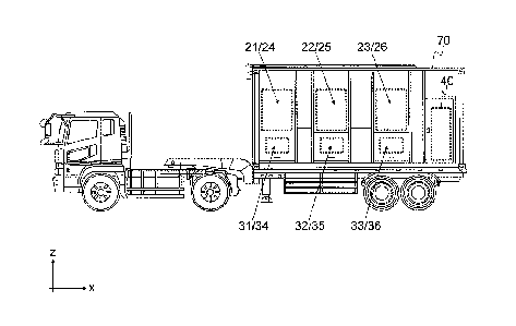
Fig. 1 is a top view illustrating a trailer equipped with
a load-carrying box containing a dry-type load testing machine
according to the present embodiment.
Fig. 2 is a side view illustrating the trailer equipped
with the load-carrying box containing the dry-type load testing
machine according to the present embodiment.
Fig. 3 is a perspective view illustrating the arrangement
of the first to sixth resistance units, the frame, the
insulators, and the first to sixth cooling fans.
Fig. 4 is a perspective view illustrating the arrangement
of the first and fourth resistance units and the insulators.
Fig. 5 is a back view illustrating the arrangement of the
first and fourth resistance units and the insulators.
Fig. 6 is a back view illustrating the arrangement of the
first and fourth resistance units and the insulators in a
configuration in which connection cables in Fig. 5 are replaced
by short-circuit bars.
12
CA 02849403 2014-08-25
95845-1PPH
Fig. 7 is a perspective view illustrating the arrangement
of the first and fourth resistance units and the insulators in
a configuration in which switching members are used for
connection.
Fig. 8 is a back view illustrating the arrangement of the
first and fourth resistance units and the insulators in the
configuration in which the switching members are used for
connection.
Fig. 9 is a perspective view illustrating each of the
switching members.
Fig. 10 is a cross-sectional configuration view
illustrating each of the switching members.
Fig. 11 is a
cross-sectional configuration view illustrating a switching
member differently structured from the switching member
illustrated in Fig. 10.
Description of Embodiments
[0033]
The present embodiment will be hereinafter described with
reference to the drawings. A dry-type load testing machine 1
according to the present invention includes a frame 10, a first
resistance unit 21 to a sixth resistance unit 26, a first cooling
fan 31 to a sixth cooling fan 36, a connection switching section
40, insulators 50, and connection cables 60 (FIGS. 1 to 5).
[0034]
The frame 10 has such a size that a shipping container
13
CA 02849403 2014-08-25
95845-1PPH
70 of a container (or high-cube container) can contain the frame
10, and the first to sixth resistance units 21 to 26 are fixed
on the frame 10 with the insulator 50 in between. A base plate
or a vibration-proof insulating rubber, for example, (not shown
in the drawings) may be provided between the insulator 50 and
the frame 10.
[0035]
For the explanation of directions, a direction in which
a transporting means, such as a trailer (or a truck or a railroad
car) , loaded with the shipping container 70 travels (the
longitudinal direction of the shipping container 70) is denoted
by a x-direction, a horizontal direction perpendicular to the
travelling direction is denoted by a y-direction, and a
perpendicular direction perpendicular to the x-direction and
the y-direction is denoted by a z-direction.
[0036]
Each of the first resistance unit 21 to the sixth
resistance unit 26 includes a plurality of steps of resistor
groups arranged in the z-direction to connect together in
parallel, each of the resistor groups being formed of a
plurality of rod-shaped resistors R parallel to the x-direction
connected together in series arranged at predetermined
intervals in the y-direction. The resistance units are used
for conducting a load test on a power supply such as a power
generator under different conditions of the load (voltage) of
the power supply, set by changing a resistor group to be used,
14
CA 02849403 2014-08-25
95845-1PPH
a method for connecting the first resistance unit 21 to the third
resistance unit 23 (or the fourth resistance unit 24 to the sixth
resistance unit 26) for, for example, neutral connection, or
a method for connecting the resistor groups.
[0037]
Although the present embodiment will be described on the
assumption that each of the first resistance unit 21 to the sixth
resistance unit 26 has 8 steps of resistor groups arranged in
the z-direction to connect together in parallel, each of which
being formed of 8 rod-shaped resistors R parallel to the
x-direction connected together in series with for example,
short-circuit bars arranged at predetermined intervals in the
y-direction, the number of resistors R arranged in each resistor
group and the number of steps of the resistor groups are not
limited to the numbers as described above.
[0038]
Each resistor group has openings in the upper and the lower
surfaces thereof for allowing cooling wind from the cooling fans
at the lower part to flow upward, and is covered with a casing
=
of an insulating material at the side surfaces thereof in order
to increase the insulation level between the resistor group and
the resistor unit next thereto.
[0039]
The serially connected resistor R forming each resistor
group is connected to the connection switching section 40 by
cables (not shown in the drawings) at their respective edges
CA 02849403 2014-08-25
95845-1PPH
at at least one side (at a side which is not connected to the
connection cables 60 described later) .
[0040]
In order to perform cooling with the cooling fans
efficiently, the resistors R of the resistor groups are arranged
so that the resistors R of the resistor groups next to each other
in the z-direction are arranged at positions intermediate
between the resistors R forming the resistor groups and the
resistors R next to the above resistors R in the y-direction.
[0041]
The first resistance unit 21 to the third resistance units
23 are arranged in the x-direction at intervals of at least a
first distance dl, and the fourth resistance unit 24 to the sixth
resistance units 26 are arranged in the x-direction at intervals
of at least the first distance dl. The first distance dl is
desirably larger than a length that needs to be kept between
resistance units next to each other in the x-direction so that
insulation can be obtained there between (for example, the first
resistance unit 21 and the second resistance unit 22) , and is
desirably a length (for example, approximately 60 cm) that
enables a worker to enter the space between the resistance units
and perform tasks.
[0042]
The first resistance unit 21 and the fourth resistance
unit 24 are arranged in the y-direction at an interval of at
least a second distance d2, the second resistance unit 22 and
16
CA 02849403 2014-08-25
95845-1PPH
the fifth resistance unit 25 are arranged in the y-direction
at an interval of at least the second distance d2, and the third
resistance unit 23 and the sixth resistance unit 26 are arranged
in the y-direction at an interval of at least the second distance
d2. The second distance d2 is desirably a length (for example,
approximately 11 cm) that needs to be kept between resistance
units next to each other in the y-direction so that insulation
can be obtained there between (for example, the first resistance
unit 21 and the fourth resistance unit 24) .
[0043]
The first resistance unit 21 and the fourth resistance
unit 24 are used for an R-phase load test, the second resistance
unit 22 and the fifth resistance unit 25 are used for an S-phase
load test, and the third resistance unit 23 and the sixth
resistance unit 26 are used for a T-phase load test
[0044]
The first cooling fan 31 to the sixth cooling fan 36 are
attached at positions under the first resistance unit 21 to the
sixth resistance unit 26, respectively, and in the upper part
of the inside of the frame 10. Further, air intake ports of
the first cooling fan 31 to the sixth cooling fan 36 are provided,
respectively, in the sides of the lower part and the bottom of
the inside of the frame 10.
[0045]
Between the first cooling fan 31 to the sixth cooling fan
36 and the first resistance unit 21 to the sixth resistance unit
17
CA 02849403 2014-08-25
95845-1PPH
26, cylindrical hoods (first hood 31a to sixth hood 36a) are
provided, respectively, that introduce cooling wind from the
first cooling fan 31 to the sixth cooling fan 36 to the first
resistance unit 21 to the sixth resistance unit 26, respectively.
The upper part of each cylindrical hood is located in the inside
of the casing covering sides of the resistor group at the
lowermost step, and is desirably separated from the casing at
a distance of at least 1 cm. The hood and the casing are formed
of an insulating material, and insulation can be maintained
without dusts stored in between by providing isolation between
the hood and the casing.
[0046]
The first resistance unit 21 to the sixth resistance unit
26 each have specifications (the number of resistors R, the
resistance value, etc.) corresponding to the rated voltage of
a target power supply of a power supply load test to be conducted
in a state in which the resistance units are not connected
together in series.
[0047]
Specifically, each of the first resistance unit 21 to the
sixth resistance unit 26 has specifications (the number of
resistors R, the resistance value, etc.) corresponding to the
rated voltage of a target power supply of a three-phase
alternating-current power supply load test to be conducted
using three of the first resistance unit 21 to the sixth
resistance unit 26.
18
CA 02849403 2014-08-25
95845-1PPH
[0048]
The first cooling fan 31 to the sixth cooling fan 36 each
have specifications (for example, cooling capability of fans)
for cooling the first resistance unit 21 to the sixth resistance
unit 26, respectively, at a power supply load test.
[ 0049]
The connection switching section 40, which has a
switching device and a control device such as a CPU, serves to
change connection to a target power supply of a load test, a
resistor group to be used, a method for connecting the first
resistance unit 21 to the third resistance unit 23 (or the fourth
resistance unit 24 to the sixth resistance unit 26) together
for, for example, neutral connection, and a method for
connecting the resistor groups. Further, a load test can be
conducted on a direct-current power supply by connecting the
resistance units in series.
[0050]
The insulator 50 is used for insulating the first
resistance unit 21 to the sixth resistance unit 26 to which high
voltages are applied from the peripheral devices (the frame 10,
the first cooling fan 31 to the sixth cooling fan 36, for
example) .
[0051]
Further, the insulator 50 is desirably provided as well
between the first resistance unit 21 and the fourth resistance
unit 24, between the second resistance unit 22 and the fifth
19
CA 02849403 2014-08-25
95845-1PPH
resistance unit 25, and between the third resistance unit 23
and the sixth resistance unit 26 in order that insulation can
be obtained between the resistance units next to each other in
the y-direction and that collisions can be prevented between
the resistance units due to movement at the transportation, for
example (see FIGS. 1 and 5) .
[0052]
The insulator 50 has specifications (size, for example)
corresponding to the rated voltage of a target power supply of
a power supply load test to be conducted using a resistance unit
group having serially connected resistor groups of two
resistance units next to each other in the y-direction with the
second distance d2 in between (the first resistance unit 21 and
the fourth resistance unit 24, the second resistance unit 22
and the fifth resistance unit 25, and the third resistance unit
23 and the sixth resistance unit 26) . In particular, the
insulator 50 provided at the bottom of the resistance unit has
a size in the z-direction of at least the second distance d2.
[0053]
Specifically, the insulator 50 has specifications (size,
for example) corresponding to the rated voltage of a target power
supply of a three-phase alternating-current power supply load
test to be conducted using 3 sets of resistance unit groups each
having serially connected resistor groups of two resistance
units next to each other in the y-direction with an interval
of at least the second distance d2 in between (the first
CA 02849403 2014-08-25
95845-1PPH
resistance unit 21 and the fourth resistance unit 24, the second
resistance unit 22 and the fifth resistance unit 25, and the
third resistance unit 23 and the sixth resistance unit 26). In
particular, the insulator 50 provided at the bottom of the
resistance unit has a size in the z-direction of at least the
second distance d2.
[0054]
In other words, the insulator 50 has specifications
corresponding to the rated voltage twice as large as the rated
voltage of a target power supply of a load test for which each
of the first resistance unit 21 to the sixth resistance unit
26 and the first cooling fan 31 to the sixth cooling fan 36 has
specifications.
[0055]
For example, when each of the first resistance unit 21
to the sixth resistance unit 26 has specifications for a
6600-volt three-phase alternating-current power supply, an
insulator 50 having specifications fora 13200-volt three-phase
alternating-current power supply is used. In this case, the
insulator 50 has a length larger by a few centimeters than an
insulator having specifications for a 6600-volt three-phase
alternating-current power supply.
[0056]
The connection cable 60 is a cable used for serially and
detachably connecting, at more than one part, resistor groups
(resistors R of resistor groups) next to each other in the
21
CA 02849403 2014-08-25
95845-1PPH
y-direction of two resistance units next to each other in the
y-direction with the second distance d2 in between.
[0057]
The number of prepared connection cables 60 is three times
as large as the number of steps of the resistor groups in each
resistor unit (in the present embodiment, 8 steps multiplied
by 3 is 24 cables). Each of the connection cables 60 connects
one terminal of a resistors R forming a resistor group which
is close to a resistance unit as a connection destination, with
a terminal of a resistor R close to the above terminal forming
a resistor group of the resistance unit as the connection
destination next to the above terminal in the y-direction.
[0058]
Although a configuration in which the resistor groups are
connected together at their respective steps with the
connection cables 60 will be described in the present embodiment,
a connection does not always need to be made between each step,
and may be made at more than one part of the plurality of the
resistor groups with the connection cables 60. It is easier
to control switching of the resistor groups at a load test when
the above configuration is employed, compared to when two
resistance units are connected together in series at only one
part (one terminal of one resistor R). The more the connecting
parts are, the easier the control of the switch becomes.
[0059]
Ring terminals (represented by a black circle in FIGS.
22
CA 02849403 2014-08-25
95845-1PPH
3 and 4) are provided at both terminals of each connection cable
60. The connection cables 60 and the resistors R can be
connected together in a detachable state in a manner that the
ring terminals are retained to fix the terminals of the
resistors R and then are screwed (or fixed with bolts).
[0060]
The shipping container 70 has opening/closing doors at
least at positions of the upper surface thereof which face the
first resistance unit 21 to the sixth resistance unit 26, at
positions of the side surfaces thereof which face the air intake
ports of the first cooling fan 31 to the sixth cooling fan 36,
and at the back surface thereof. A load test is conducted in
a manner that the doors at the side surfaces are opened for
letting air in, the doors at the upper surface are opened for
letting air out, and the doors at the back surface are opened
for electric connection to a target three-phase
alternating-current power supply of the load test or operation
(load test operation) of the connection switching section 40.
[0061]
With the connection cables, resistor groups next to one
another in the y-direction of the two resistance units are
connected together in series.
[0062]
In this case, since a resistance value twice as large as
the resistance value of a single resistance unit can be obtained
with a single resistance unit group, it is possible to conduct,
23
CA 02849403 2014-08-25
95845-1PPH
with one resistance unit group, a load test on a power supply
having a voltage twice as large as the voltage of a target power
supply of a load test that can be conducted with one resistance
unit.
[0063]
Specifically, when each of the first resistance unit 21
to the sixth resistance unit 26 has specifications
corresponding to a 6600-volt three-phase alternating-current
power supply, it is possible to conduct a load test on a
13200-volt three-phase alternating-current power supply by
combining the six resistance units in pairs and forming three
different resistance unit groups.
[0064]
Although a voltage applied to one resistance unit group
is twice as large as a voltage applied to one resistance unit,
sufficient isolation for separation is ensured and insulation
from the peripheral devices of the resistance units such as the
frame 10 and the first cooling fan 31 to the sixth cooling fan
36 as well as insulation among the resistance units can be
maintained even when the double voltage is applied, since an
insulator having specifications which consider a voltage to be
applied to one resistance unit group is used as the insulator
50.
[0065]
Since the connection cables 60 are connected to their
corresponding resistor groups, it is easier to control
24
CA 02849403 2014-08-25
95845-1PPH
switching of the resistor groups at a load test, compared to
when two resistance units are connected together only at one
part (at one terminal of one resistor R).
[0066]
The first resistance unit 21 to the sixth resistance unit
26 and the first cooling fan 31 to the sixth cooling fan 36 may
consider the voltage of a target power supply of a load test
that can be conducted with one resistance unit. Hence, this
configuration can be realized using ready-made parts more
easily than a configuration in which the number or the lengths
of the resistors Rare increased so that specifications similar
to the specifications that can be obtained with one resistance
unit group can be obtained with one resistance unit.
[0067]
Moreover, since the resistors R extend in the x-direction
(the longitudinal direction of the shipping container 70), it
is hardly necessary to change the size of each resistance unit
in the y-direction if the rod-shaped member forming each
resistor R is made longer, and there is less limitation on
loading a load testing machine on a transporting means such as
a trailer, a truck, or a railroad car (the resistors R cannot
be made longer than a specified length when the resistors R are
formed to extend in the y-direction, since a vehicle has only
a limited width in the y-direction).
[0068]
Hence, it is easier to place the dry-type load testing
CA 02849403 2014-08-25
95845-1PPH
machine 1 into the shipping container 70 and move the shipping
container 70 by loading the shipping container 70 on a
transporting means such as a trailer, a truck or a railroad car.
[0069]
Further, compared to when the connection cables 60 are
used for a load test, lower-voltage power supply can be
subjected to a load test when the connection cables 60 are easily
removed from the resistors R and only the first to third
resistance units 21 to 23 (or only the fourth to sixth resistance
units 24 to 26) are used for the load test.
[0070]
Further, provision of isolation of at least the first
distance dl makes it possible to obtain an insulation level
between the resistance units in the x-direction higher than the
insulation level obtained in a configuration in which such
isolation is not provided, and enables a worker to enter a space
between the resistance units and easily perform tasks of, for
example, interconnection (in particular, removing and
attaching the connection cables 60) . Moreover, provision of
isolation of at least the second distance d2 makes it possible
to obtain an insulation level between the resistance units in
the y-direction higher than the insulation level obtained in
a configuration in which such isolation is not provided.
[0071]
Although an example in which the resistors R are serially
connected in the resistor groups has been described in the
26
CA 02849403 2014-08-25
95845-1PPH
present embodiment, part of or all of the resistors R can be
connected together in parallel by changing the manner in which
the resistors Rare connected at their respective edges. Hence,
the manner of connecting the resistors R in the resistor groups
may be switched between a parallel connection and a serial
connection, using the short-circuit bars or the connection
switching section 40. When this manner is employed, it is
possible to conduct a load test on a low-voltage three-phase
alternating-current power supply by increasing the number of
parts in the resistor groups where a parallel connection is
made.
[0072]
Moreover, although an example in which the connection
cables 60 is used for connecting the resistor group of one
resistor unit and the resistor group of another resistor unit
has been described in the present embodiment, connection
members to be used for connecting the resistor groups together
are not limited to the cables. Specifically, a short-circuit
bar 61 may be used to connect one resistor group and another
resistor group together as a short-circuit bar is used to
connect terminals of resistors R together (see Fig. 6).
[0073]
Moreover, although an example in which the connections
of the connection cables 60 or the short-circuit bars 61 with
the resistors R are direct connections has been described in
the present embodiment, the connections may be made via
27
CA 02849403 2014-08-25
95845-1PPli
switching members 80 each including a case 87, the case 87
containing a fixed contact point 81, a movable contact point
83, and a driving member 85 that drives the movable contact point
83 and being filled with an inert gas of, for example, nitrogen
(see FIGS. 7 to 10) .
[0074]
Specifically, each switching member 80 has the fixed
contact point 81, the movable contact point 83, the driving
member 85, a lead line 86, and the case 87, and is set in a
position near a terminal of a resistor R of the resistor group
which is connected to the connection cable 60 or the
short-circuit bar 61.
[0075]
A terminal (first terminal 81a) of the switching member
80 which protrudes from one fixed contact point 81 to the outside
of the case 87 is connected to a terminal of the resistor R,
and a terminal (second terminal 81b) thereof which protrudes
from the other fixed contact point 81 to the outside of the case
87 is connected to the connection cable 60 or the short-circuit
bar 61. The resistors R and the first terminal 81a are
constantly connected together, while one of the connection
cable 60 and the short-circuit bar 61 is connected to the second
terminal 81b only when the resistance units are to be connected
together. An insulating wail 88 is desirably provided (see Fig.
28
CA 02849403 2014-08-25
95845-1PPH
9) between the first terminal 81a and the second terminal 81b
so that the connection cable 60 or the short-circuit bar 61 to
be attached to the second terminal 81b does not become in contact
with the first terminal 81a by mistake when is being attached
to the second terminal 81b or so that short circuit does not
occur between the first terminal 81a and the second terminal
81b.
[0076]
The movable contact point 83 is driven by the driving
member 85 and is switched between an on-state and an off-state
(the on-state is a state in which the movable contact point 83
is in contact with the fixed contact point 81 and the off-state
is a state in which the movable contact point 83 is not in contact
with the fixed contact point 81). The connection cable 60 or
the short-circuit bar 61 is connected to the second terminal
81b in the off-state.
[0077]
The driving member 85 is connected to the connection
switching section 40 via the lead line 86, and the operation
of the driving member 85 (switching between the on-state and
the off-state) is controlled by the connection switching
section 40.
[0078]
The case 87 contains the fixed contact point 81, the
movable contact point 83, and the driving member 85, and is
filled with an inert gas.
29
CA 02849403 2014-08-25
95845-1PPH
[0079]
If the connection cable GO or the short-circuit bar el
is connected to the switching member 90 (the second terminal
81b) in the off-state in which the fixed contact point 81 and
the movable contact point 83 are not in contact with each other,
it is possible to reduce a user's risk of getting electrical
shock due to leakage of currents of resistance units to the
outside when the user is holding the connection cable 60 or the
short-circuit bar 61.
[0080]
Moreover, since the case 87 is filled with an inert gas,
the possibility of generation of a spark is low between the fixed
contact point 81 and the movable contact point 83 in the
off-state (or a state immediately before the on-state) in which
the fixed contact point 81 and the removable contact point 83
are not in contact with each other.
[0081]
Note that cables (a first cable 82a and a second cable
82h) protruding from the fixed contact points 81 to the outside
of the case 87 may be provided instead of the first terminal
81a and the second terminal 81b (see Fig. 11).
[0082]
The first cable 82a is connected at one side thereof to
one fixed contact point 81 while the first cable 82a is connected
at the other side thereof to a resistor R. The second cable
82b is connected at one side thereof to the other fixed contact
CA 02849403 2014-08-25
95845-1PPH
point 81 while the second cable 82bis connected at the other
side thereof to the connection cable 60 or the short-circuit
bar 61.
[0083]
A region of the inside of the case 87 which is in contact
with the fixed contact point 81 for the first cable 82a, a region
of the inside of the case 87 which is in contact with the fixed
contact point 81 for the second cable 82b, and a region of the
inside of the case 87 which contains the fixed contact point
81 and the movable contact point 83 are surrounded by a sealed
container (internal case) 90, and the inside of the sealed
container 90 is filled with an inert gas of, for example,
nitrogen. An insulating member formed of, for example, butyl
rubber is filled in a region between the sealed container 90
and the case 87 which contains at least the area between the
first cable 82a and the second cable 82b, so that short-circuit
does not occur between the first cable 82a and the second cable
82b.
[0084]
Fig. 11 illustrates an example in which the insulating
member is filled in all of the region between the sealed
container 90 and the case 87. The region filled with the
insulating member is represented by a checkered pattern. The
lead line 86 (not shown in Fig. 11) is connected via a control
terminal 89 extending from the driving member 85.
[0085]
31
CA 02849403 2014-08-25
95845-1PPH
It is to be noted that although Fig. 11 illustrates the
case where the first cable 82a and one fixed contact point 81
are arranged separately from each other and the second cable
82b and the other fixed contact point 81 are arranged separately
from each other, the first cable 82a and one fixed contact point
81 may be arranged integrally with each other and the second
cable 82b and the other fixed contact point 81 may be arranged
integrally with each other so that the respective edges of the
first and second cables 82a and 82b function as the fixed contact
points 81 and are in contact with the movable contact point 83.
Reference Signs List
[0086]
1 dry-type load testing machine
10 frame
21-26 first to sixth resistance units
31-36 first to sixth cooling fans
31a-36a first to sixth hoods
40 connection switching section
50 insulator
60 connection cable
61 short-circuit bar
70 shipping container
80 switching member
81 fixed contact point
81a, 81b first and second terminals
32
CA 02849403 2014-08-25
95845-1PPH
82a, 82b first and second cables
83 movable contact point
85 driving member
86 lead line
87 case
88 insulating wall
89 control terminal
90 sealed container (internal case)
dl, d2 first and second distances
33