Note : Les descriptions sont présentées dans la langue officielle dans laquelle elles ont été soumises.
CA 02849474 2015-08-11
PORTABLE PRESSURIZED POWER
SOURCE FOR FASTENER DRIVING TOOL
10
BACKGROUND
The present invention relates generally to fastener driving tools, and
more specifically to such a tool having a pre-pressurized power delivery
source.
Power tools for use in driving fasteners into work pieces are known
in the art. Such tools can be operated by a variety of power sources,
including
pneumatic, combustion, electric or powder-activated power sources. In some
power tools, the power source is integrated with a housing of the tool for
easy
portability. Other applications require power to be fed with a feed line from
an
external source, such as pneumatic tools operated by an air compressor.
Fastener driving tools of this type, and particularly pneumatically
powered tools, include a metal housing and a magazine portion that is attached
to
the housing and/or the handle. Generally, the magazine retains a supply of
fasteners which are fed to a drive track in the housing configured for
receiving and
1
CA 02849474 2015-08-11
=
guiding a fastener as it is driven by a reciprocating piston and driver blade
from the
drive track into a work piece.
A suitable pneumatically powered fastener-driving tool with a portable
power source is disclosed in US Patent No. 6,876,379, which may be referred to
for
- further details. In such a tool, the tool housing defines a main chamber
having a cylinder for accommodating reciprocation of the driver blade and
piston.
The driving stroke of the piston moves a driver blade in the drive track that
impacts a fastener to drive the fastener into a work piece. The piston is
powered
by a pneumatic power source, most preferably a portable container or vessel of
compressed gas such as carbon dioxide or the like, which forces the piston in
a
driving direction under operator control through pulling of a trigger. The
piston
also configured to be oppositely driven by a partial vacuum or other known
apparatus in a return stroke to the retracted or pre-driving position.
One drawback of conventional tools of this type is that the
mechanical mechanism used to trigger and power the fastener driving power
cycle
is relatively inefficient in the use of the limited supply of compressed gas.
A main
result is that the operational life of such tools is relatively short and
unacceptable
to many users. As such, this type of tool has had a limited commercial
application.
SUMMARY
2
CA 02849474 2014-03-20
WO 2013/052445
PCT/US2012/058404
The present, preferably pressurized fluid-powered fastener driving
tool addresses the drawbacks of previous tools of this type and features an
electrical control circuit or program connected to a solenoid valve for more
accurate dosing of the compressed fluid, preferably a gas, used to power the
tool.
The control program, preferably incorporated in a microprocessor, is connected
to
the solenoid valve to control the flow of fluid to a piston and driver blade
for
driving a fastener. A periodic opening of the solenoid under electrical
control
enhances the efficient use of the compressed fluid in the container. The
opening
time (which can be user adjustable) results in a quantity of fluid being
introduced
into the drive cylinder to act upon the drive piston and subsequently drive
the
fastener. The tool is optionally configured for returning the piston via an
urging
member using energy stored during the driving stroke, or by re-directing the
drive
gas volume to the underside of the drive piston. Alternately, a small amount
of
additional fluid may be directed to the underside of the piston to accomplish
return. A combination of two or more of the described methods is also
contemplated.
In addition, the compressed gas used to drive the piston and driver
blade in the fastener driving process is optionally retained in the tool and
recycled
for both returning the piston to the initial position and for use in driving
subsequent fasteners. This return may be supplemented or replaced by a
mechanical return such as a resilient bumper and a return spring. As a result,
the
3
CA 02849474 2014-03-20
WO 2013/052445
PCT/US2012/058404
portable compressed fluid supply in the present tool lasts longer than
conventional
tools.
Another feature of the present fastener-driving tool relates to the
operational attribute of such compressed power sources, in that the container
includes a supply of pressurized liquid along with the supply of compressed
gas.
When the tool is designed to be powered by compressed gas, in the event the
liquid flows into the tool, performance is impeded. To address this problem,
the
compressed power source is provided with an anti-siphon device for preventing
the flow of compressed liquid into the tool. Such an anti-siphon device is
designed for use in either a reusable or a disposable pressurized container.
In
some embodiments, the anti-siphon tube is provided with specialized structures
for
impeding the flow of pressurized liquid into the tube, including a drip shelf,
a
bottom end with a restricted opening, and a depending protective ring.
More specifically, a pressurized fluid container is provided for use
with a fastener-driving tool, the container having an outer shell defining an
inner
chamber, having an open neck and an effective height, a closure sealingly
engaged
on the open neck, and a tube depending from the closure.
In another embodiment, a driver tool powered by compressed gas is
provided, including a magazine for storing and supplying fasteners to a tool
nose,
a cylinder with a reciprocating piston attached to a driver blade, and a
compressed
gas container being in fluid communication with the reciprocating piston and
having an anti-siphon tube.
4
CA 02849474 2016-05-24
In still another embodiment, a pressurized fluid container is
provided. The container includes an outer shell defining an inner chamber,
having
an open neck and an effective height, a closure sealingly engaged on the open
neck, a flexible tube depending from the closure, and a float attached to a
free end
of the tube and in contact with a liquid phase of a fluid in the container.
In another embodiment, a driver tool powered by compressed gas is
provided. The driver tool includes a magazine associated with the tool for
storing
and supplying fasteners to a tool nose; a cylinder in the tool with a
reciprocating
piston attached to a driver blade sequentially engaging fasteners from the
magazine
as they are fed into the tool nose; and a compressed gas container in fluid
communication with the reciprocating piston and having an anti-siphon tube
that
has at least one liquid entry prevention feature that includes at least one of
a
conically flared drip shelf, a substantially closed free end and a depending
annular
shield.
In a further embodiment, a driver tool powered by compressed gas
is provided. The driver tool includes a magazine associated with the tool for
storing
and supplying fasteners to a tool nose; a cylinder in the tool with a
reciprocating
piston attached to a driver blade sequentially engaging fasteners from the
magazine
as they are fed into the too nose; and a compressed gas container in fluid
communication with the reciprocating piston and having an anti-siphon tube
5
CA 02849474 2016-05-24
extending into the container past a narrowed neck of the container. The
compressed
gas container is disposed substantially perpendicular to the cylinder and
closer to a
work contact element than to a rear side of the cylinder accommodating a
piston
start position.
In another embodiment, a driver tool powered by compressed gas is
provided. The driver tool includes a magazine associated with the tool for
storing
and supplying fasteners to a tool nose; a cylinder in the tool with a
reciprocating
piston attached to a driver blade sequentially engaging fasteners from the
magazine
as they are fed into the tool nose; and a compressed gas container in fluid
communication with the reciprocating piston and having an anti-siphon tube.
The
anti-siphon tube has a length that is approximately 33% to 66% of an effective
height of the container, the effective height is measured internally from a
bottom of
the container upward to a point where a largest diameter of the container
begins to
narrow towards a neck of the container.
BRIEF DESCRIPTION OF THE DRAWINGS
FIG. 1 is a vertical section of a prior art fastener tool powered by a
portable compressed fluid source;
FIG. 2 is a fragmentary schematic of the present tool;
FIG. 3 is a vertical section of a suitable portable compressed fluid
container for use with the present tool;
FIG. 4A is an enlarged fragmentary view of a siphon tube used in
5a
CA 02849474 2016-05-24
_
the fluid container of FIG. 3;
FIG. 4B is a bottom plan view of the siphon tube of FIG. 4 A;
FIG. 5 is a vertical section of the gas source of FIG. 3 shown
inverted;
FIG. 6 is a fragmentary view of the fluid source of FIG. 3 shown
disposed at an angle;
FIG. 7 is a side elevation of an alternate embodiment of the
compressed fluid container of FIG. 3;
FIG. 8 is a vertical cross-section of the container of FIG. 7;
FIG. 9 is an enlarged fragmentary vertical cross-section of an
alternate embodiment of the container of FIG. 7; and
FIG. 10 is an enlarged fragmentary vertical cross-section of the
container of FIG. 9 showing connection of the container to a tool; and
FIG. 11 is a fragmentary vertical section of another alternate
embodiment of the container of FIG. 9.
5b
CA 02849474 2016-05-24
DETAILED DESCRIPTION
Referring now to FIG. 1, a suitable prior art fastener-driving tool that
is compatible with the present invention is generally designated 10. This tool
is
described in greater detail in commonly-assigned US Patent No. 6,786,379 which
may be referred to for futher details. However, it is also contemplated that
the
present invention is applicable in other types of pneumatically powered
fastener-
driving tools that are well known in the art, and is not limited to the
illustrated
embodiment. The tool 10 includes a grip frame or housing 12, made of a variety
of materials, but preferably metal to withstand the forces generated by
pressurized
gas contained within. It is contemplated that the housing 12 be provided in a
variety of configurations, both enclosed and open, frame-style to provide a
mounting point for the various tool components discussed below. Included in
the
housing 12 is a handle 14, and a tool nose 16 having a shear block and
defining an
outlet 18 for the passage of fasteners 20 into a work piece. It is also
contemplated
6
CA 02849474 2014-03-20
WO 2013/052445
PCT/US2012/058404
that the housing 12 may take a variety of shapes and optionally partially,
rather
than completely encloses at least some of the tool components.
A fastener storage device or magazine 22 retains a supply of the
fasteners 20 and includes a biasing element (not shown) for urging the
fasteners
toward the nose 16. While a strip-style magazine 22 is depicted, other
conventional fastener storage device types are contemplated, including but not
limited to rotary or coil magazines.
Preferably removably secured to the magazine 22 for support and
replacement purposes is a portable vessel or container 24 of pressurized
fluid,
which is contemplated as being a pressurized gas, preferably carbon dioxide
(CO2)
or nitrous oxide (N20). Other pressurized gases are contemplated, including
nitrogen (N2) and air. The following description of a preferred embodiment
utilizes self contained pre-pressurized CO2 in a two-phase mixture as the
power
source. An advantage of using a two-phase mixture of CO2 is that when the
mixture is stored in the removable container 24 that is in equilibrium and has
two
phases of CO2 remaining in the vessel, a constant pressure of the gas phase is
maintained. That is, as gaseous CO2 is removed from the vessel 24 to power the
fastener-driving tool 10, liquid CO2 changes to a gas phase to replace lost
gaseous
CO2 and maintain a constant pressure in the vessel. Another advantage of using
a
pressurized power source such as CO2 is that, due to the relatively high
pressure of
the gas (in the range of 800 psi), the number and size of the moving tool
parts can
be reduced. This reduces the likelihood of experiencing a mechanical failure,
7
CA 02849474 2014-03-20
WO 2013/052445
PCT/US2012/058404
simplifies repairs, and lowers the overall manufacturing costs. It is also
contemplated that the tool 10 is optionally powered by the pressurized liquid
phase
of CO2 Fluid communication between the gas container 24 and an inner chamber
26 of the housing 12 is effected by a conduit 28, here a flexible hose;
however
other conduits are contemplated, as well as a direct connection between the
container 24 and the housing 12. An optional adjustable regulator 30 reduces
pressure within the inner chamber 26 to approximately 400 psi or other
pressures
as known to those skilled in the art.
A pneumatic engine 32 includes a cylinder 34 enclosing a
reciprocating piston 36 attached to a driver blade 38. Depending on the
application, the piston 36 and the drive blade 38 are separate parts fastened
together or are integrally joined. As is known in the art, reciprocation of
the driver
blade 38 in a passageway (not shown) defined by the tool nose 16 drives
fasteners
out the outlet 18. Compressed gas provided by the container 24 fills and
15 pressurizes the inner chamber 26.
A mechanical linkage controls the flow of compressed fluid within
the inner chamber and powers the reciprocal action of the piston 36 and the
driver
blade 38. Included in this linkage is a pivoting trigger 40 which is biased,
preferably by a spring 42, or by magnets or other known structures. A trigger
arm
20 44 engages a biased sear 46 which in turn releases a biased activating
bolt or valve
opening member 48 that is held in place by the internal pneumatic pressure of
the
inner chamber 26. A trigger piston 50 at an end of the valve-opening member 48
8
CA 02849474 2014-03-20
WO 2013/052445
PCT/US2012/058404
engages a respective stem 52 of a counter-biased control valve 54 for
periodically
opening a supply port 56 for pressurizing the piston 36 to initiate a fastener-
driving cycle.
As is known in the art, as the piston 36 is driven down the cylinder
34, pressurized gas is vented through escape ports 58 in communication with a
return chamber 60 that temporarily stores the pressurized gas which is then
used to
return the piston 36 to the start position depicted in FIG. 1. Pressurized gas
can
also be provided directly from the container 24 for assisting in return of the
piston
36. Piston return is also facilitated by a resilient rubber-like bumper 62
located at
an end of the cylinder 34 closest to the tool nose 16. As the piston 36
returns to
the start position, gas ahead of the piston is vented to atmosphere from the
cylinder through a main port 64, which also receives the pressurized gas
released
by the control valve 54 at the beginning of the driving cycle. It has been
found
that the above-described system is relatively inefficient in the use of
pressurized
gas, and thus limits the operational life of the gas container 24 and impairs
the
commercial adaptability of the tool 10.
Referring now to FIG. 2, the present pneumatic drive system is
incorporated into a fastener-driving tool generally designated 70. Components
shared with the tool 10 are designated with identical reference numbers. The
present fastener driver tool 70 includes the following major component groups.
These are: the fluid storage vessel 24, the pressure regulator 30, an electro-
mechanical solenoid valve 72, the drive cylinder 34 and the piston 36,
associated
9
CA 02849474 2014-03-20
WO 2013/052445
PCT/US2012/058404
electrical control system, program or control circuitry (all three are
considered
equivalent or synonymous) 74 and the conventional magazine 22 and the
associated fastener feeder mechanism.
An important feature of the present tool 70 relates to the use of the
control circuitry 74 that is operatively associated with the housing 12 and is
configured for electrically controlling a flow of compressed fluid for driving
the
piston 36. In the preferred embodiment, this control is achieved by at least
one
microprocessor 76 or similar control module powered by a power source 78,
preferably a battery or other conventional power source, and preferably having
a
user interface 80. The battery 78 and the interface 80 are preferably
connected to
the control system 76 via wiring 82, or optionally wirelessly, as feasible.
The
electro-magnetic solenoid valve 72 is electrically connected to the control
system
76 via the wiring 82 and is operationally disposed relative to the supply port
56 or
the main port 64 as is known in the art of pneumatic power technology for
directly
controlling the flow of pressurized fluid to the piston 36.
Through the user interface 80, the user can adjust the performance of
the tool 70, including among other things the duration of energization time of
the
solenoid valve 72. Depending on the application, additional energization time
provides more driving power to the fastener 20 which may be needed for longer
fasteners and/or for harder substrates. As is known in the art, the user
interface 80
may include a visual display, LED indicators, a touch screen, user actuated
buttons
and similar control interfaces.
CA 02849474 2014-03-20
WO 2013/052445
PCT/US2012/058404
In the tool 70, the pressurized fluid container 24 is directly
connected to the tool housing 12 through a fitting 86 that in turn is in fluid
communication with the regulator 30. Thus, the conduit 28 is eliminated as
shown, but is contemplated as an option in the event the user wishes to
personally
carry the container 24 to reduce the weight of the tool 70. An outlet 88 of
the
regulator 30 is in fluid communication with a solenoid intake tube 90. If
desired,
a pressure sensor and gauge 92 is optionally located in the relatively low-
pressure
intake tube 90, and/or at the relatively high pressure mounting fitting 86 for
monitoring pneumatic pressure between the container 24 and the intake tube 90.
As is the case in the tool 10, the regulator 30 is adjustable for changing
operational
pressures as needed.
A further feature of the present tool 70 is that the control system 74
is optionally programmed to receive and compare pressure data from the
respective pressure sensors/gauges 92 located in the flow path before and
after the
regulator 30, the gauges respectively identified as 92a and 92b. Each of the
gauges 92a, 92b is electrically connected to the control system 74, and the
micro
processor 76 is configured to compare the transmitted pressure data. In the
event
both gauges transmit a similar pressure value, the significance is that the
container
24 is close to being empty, and the user has a limited number of fasteners
that can
be driven before a refill container is obtained. The control system 74 is
configured
such that the user interface 80 displays or emits an alarm to the user to
replace the
container 24. It is contemplated that the alarm is visual and/or audible
and/or
11
CA 02849474 2014-03-20
WO 2013/052445
PCT/US2012/058404
sensory. The precise pressure value that triggers the alarm may vary to suit
the
situation.
Another feature of the tool 70 is that the trigger 40 is electrically
connected to the control system 74 through a switch 94, which is preferably a
micro switch or similar switching device, such as an optical or magnetically
triggered switch, and suitable wiring 82. Upon closing of the switch 94, the
control system 74 energizes the solenoid valve 72 for periodically opening and
allowing a dose of pressurized fluid from the container 24. The period of time
of
energization of the valve 72 is user adjustable via the user interface 80.
Also, as is common in fastener driving tools, the nose 16 is equipped
with a reciprocating work piece contact element (WCE) 96 that retracts
relative to
the nose 16 to permit the driving of a fastener 20. In the tool 70, the WCE 96
is
electrically connected to a switch 98, similar to the switch 94 and preferably
a
micro switch or similar switch that is triggered by WCE movement, such as
magnetically or optically, for sending a signal to the control system 74.
Preferably, the microprocessor 76 is programmed so that the solenoid valve 72
will open only when the switches 94 and 98 are closed or otherwise energized.
The specific order of energization of the switches 94, 98 may vary to suit the
desired operation of the tool 70. For
so-called sequential operation, the
microprocessor 76 is configured such that the switch 98 is energized before
the
micro switch 94. Alternatively, in so-called repetitive operation, the micro
switch
94 is energized before the micro switch 98. The microprocessor 76 is
12
CA 02849474 2014-03-20
WO 2013/052445
PCT/US2012/058404
programmed to provide a sufficient energization time for the solenoid valve 72
to
enable the piston 36 to reach the opposite end of the cylinder 34 adjacent the
bumper 62. At the expiration of the allotted time period, the valve 72 is then
closed, shutting off the flow of pressurized gas and enabling piston return.
To enhance piston return at the end of the driving cycle, in addition
to the bumper 62 and pneumatic return, the present tool 70 is optionally
equipped
with an in-cylinder return spring 100 which biases the piston 36 to the start
position shown in FIG. 2. Preferably, the return spring 100 is of the helical
type
which surrounds the driver blade 38; however other configurations are
contemplated. The biasing force of the spring 100 is selected so as not to
appreciably impair the driving force of the piston 36. As the piston 36 is
returned,
any residual gas above or in front of the piston is vented to atmosphere
through an
exhaust port 102 in the solenoid valve 72.
Still another feature of the tool 70 is at least one tool
condition indicator 104, shown on the user interface 80; however other
locations
are contemplated, including on the housing 12. The tool condition indicators
104
are contemplated to include at least one of a visual indicator, an audible
indicator,
and a tactile indicator, such as a vibrating indicator. In the case of a
visual
indicator for the condition indicator 104, the indicator is contemplated to be
in the
form of at least one of a single LED, an LED bank and a screen. Information
displayed or indicated by the indicator 104 includes tool temperature, number
of
13
CA 02849474 2014-03-20
WO 2013/052445
PCT/US2012/058404
fasteners remaining, status of battery charge, total fasteners driven,
internal tool
pressure, fastener driving pressure (regulator adjustment), or the like.
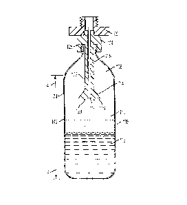
Referring now to FIGs. 3, 4A and 4B, when gas such as CO2 is used
as the power source, it is important for efficiency and power consistency to
prevent liquid CO2 from entering the inner chamber 26. Anti-siphon tubes are
known in the art. These are typically installed in the vessel or container 24,
which
is often refillable, and are bent from a central axis vessel according to the
desired
bottle orientation. This requires "clocking" the tube after determining where
the
valve attachment threads stop on the top of the vessel. Proper orientation of
the
anti-siphon tube is a lengthy process and does not provide liquid free flow in
all
vessel orientations. Also, if the bent angle of the tube is improperly
positioned,
pressurized liquid may enter the tube, depending on the orientation of the
tool.
This problem is more prevalent when the tool 70 is used at odd angles for
driving
fasteners in areas with limited access.
Accordingly, the pressurized fluid vessel or container 24 is
preferably supplied with a tube 106, preferably an anti-siphon tube configured
for
depending into an interior chamber 108 of the tube. The purpose of the anti-
siphon tube 106 is to prevent the flow of pressurized gas such as CO2 in the
liquid
phase from being drawn into the tool inner chamber 26 or into the regulator 30
where it has been found to impair tool performance. This problem has been
found
to occur more frequently when conventional tools 10 are used at an angle to
vertical, or are even inverted from the orientation depicted in FIG. 1.
Preferably,
14
CA 02849474 2014-03-20
WO 2013/052445
PCT/US2012/058404
the length of the anti-siphon tube 106 is approximately 33% to 66% of an
effective
interior axial length "A" of the container 24. More preferably, the length of
the
siphon tube 106 is approximately 50% of the effective interior axial length
"A" of
the container 24. It is contemplated that the length of the anti-siphon tube
106 is
variable depending on the amount of liquid phase fluid in the container 24 at
the
initial or fill condition or state. Depending on the application, the tube 106
may be
a siphon tube and thus extends almost the full effective length "A" at 106'
(FIG. 8
shown in phantom) of the container 24 and into a liquid phase of the
pressurized
fluid.
More specifically, the pressurized gas in the container 24 is depicted
as being in a gas phase 110 and a liquid phase 112. As the tool 10 is angled,
the
tendency for the liquid phase 112 to enter the intake conduit 28 or equivalent
connection fitting 86 is increased. Accordingly, the present anti-siphon tube
106
is preferably provided with structure for impeding the flow of the liquid
phase 112
into the tube. In the preferred embodiment, this structure takes the form of a
flared, generally conical drip shelf 114 formed at a free end of the tube 106,
a
substantially closed bottom 116 with a relatively small intake opening 118,
and at
least one depending annular protective shield 120. These structures combine to
impede the entry of pressurized gas in the liquid phase 112 into the tube 106.
In
addition, the anti-siphon tube 106 is provided with a tubular shank 122 used
to
calculate the desired length relative to the container effective length "A,"
regardless of whether or not the drip shelf 114 and the shield 102 are
provided.
CA 02849474 2014-03-20
WO 2013/052445
PCT/US2012/058404
Opposite the intake opening 118, the anti-siphon tube 106 is
connected to a closure 124 taking the form of a plug that sealingly engages an
open neck 126 of the container 24. As shown, and particularly for use in
refillable
containers 24, the plug 124 is threadably engaged on the neck 126; however
other
attachment technologies are contemplated to retain the gas within the
container 24
at the desired pressure.
As seen in FIGs. 5 and 6, as the container 24 is angled or inverted,
the latter position often used for refilling the container, the configuration
of the
anti-siphon tube 106 prevents the unwanted intake of pressurized gas in the
liquid
phase 112.
Referring now to FIGs. 7 and 8, an alternate embodiment of the
container 24 is generally designated 130. Components shared with the container
24 are designated with identical reference numbers. The main difference
between
the containers 24 and 130 is that the former is refillable, and the latter is
disposable. As such, the container 130 has a closure 132 taking the form of a
cap
that is sealably secured to the open neck 126. The anti-siphon tube 106 is
fastened, as by welding, chemical adhesive, integrally formed such as by
molding
drawing of metal or the like to the cap 132, and depends into an internal
chamber
134 of the container 130 defined by an outer shell 136.
As described above in relation to the container 24, the anti-siphon
tube 106 extends between about 33% and 66% of the effective height "A" of the
container, and more specifically about 50% of the effective height, but being
16
CA 02849474 2014-03-20
WO 2013/052445
PCT/US2012/058404
variable as described above. For the purposes of the present invention, the
"effective height" is measured internally from a bottom upward to a point
where a
largest diameter of the container 24 begins to narrow towards the neck 126.
This
length has been found to reduce the tendency for pressurized liquid within the
container 130 to enter the tube. To support the tube 106 within the chamber
134, a
bulkhead 138 extends radially from the tube and contacts an inner wall 140 of
the
chamber in a body portion 142 of the container.
Referring now to FIGs. 8 and 10, the cap 132 is preferably frangible,
and, as is known in the art, is pierced by a pointed puncture device 144 in
fluid
communication with the inner housing chamber 26 by a conduit 28 or equivalent
structure. It is contemplated that in the container 130, the tube 106 is
optionally
provided with at least one of the conical drip shelf 114, the substantially
closed
bottom end 116, the restricted opening 118 and the depending protective ring
120
as seen in FIGs. 4A, 4B.
Referring now to FIG. 9, an alternate embodiment of the container
130 is generally designated 150. Components shared with the containers 24 and
130 are designated with identical reference numbers. A main difference between
the containers 130 and 150 is that the latter has a bulkhead 152 extending
radially
from the anti-siphon tube 106 and engaging the inner wall 138 of the chamber
134
in the region of the neck 126, as opposed to the body portion 142. The
container
150 is also optionally equipped with at least one of the conical drip shelf
114, the
17
CA 02849474 2014-03-20
WO 2013/052445
PCT/US2012/058404
substantially closed bottom end 116, the restricted opening 118 and the
depending
protective ring 120 as seen in FIGs. 4A, 4B.
In the present tool 70 configured for sequential operation, the
fastener driving cycle sequence is as follows with the tool at rest and a
compressed
gas vessel 24 attached. Next, the operator places the WCE 96 against the work
surface and pulls the trigger 40. The switch 94 is electrically connected to
the
trigger 40, and once activated or energized, signals control circuitry or
equivalent
programming in the control system or microprocessor 76 to activate the firing
sequence.
A signal is sent from the control circuit to open the solenoid valve
72. Upon opening, the valve 72 allows pressurized gas to flow from the
container
24 to the regulator 30 where the pressure is reduced (typically to 80-500
psi). The
gas then flows through the now open solenoid valve 72 and into the drive
cylinder
34. Upon receipt of the flow of pressurized gas, the drive piston 36 then
descends,
comes in contact with the next fastener 20 to be driven, and then subsequently
drives the fastener into the work surface.
If so equipped, the return spring 100 or other energy storing device
installed on the underside of the piston 36 compresses to provide energy to
urge
the piston back to the initial position after the drive cycle is complete.
Upon
expiration of the control timing signal, adjustable via the user interface 80,
the
solenoid valve 72 closes, shutting off the supply of gas to the piston 36. It
is
contemplated that the valve 72 is closed before the piston 36 has completed
its
18
CA 02849474 2014-03-20
WO 2013/052445
PCT/US2012/058404
travel down the cylinder 34. Upon descending to the bottom of the cylinder 34,
the piston 36 is returned to the initial position by the stored energy in the
return
spring 100. Alternately or in addition to the return spring 100, the partially
expanded gas in the cylinder 34 above the piston 36 is allowed to exit from
the
cylinder volume above the piston and be routed to the underside of the piston.
The
solenoid valve 72 is allowed, through the exhaust valve 102, to vent the
volume
above the piston 36 to atmospheric pressure and to allow the force under the
piston
(spring, gas pressure or combination) to displace the piston back to the top
of the
cylinder 34.
Repetitive operation is also contemplated with the second switch 98
connected to the WCE 96. The control circuitry is set to the contact fire
mode.
The switch 98, in communication with the WCE 96, is activated by the operator
pressing the WCE against the work surface after the trigger switch 94 is first
activated. At this point, the driving sequence is initiated.
The disclosed anti-siphon tube 106 has a length of between 33% and
66% (50% length preferred for a fluid charge having less than 50% liquid
charge
in an initial state of the vessel 24) of the effective length "A" of the
interior of the
typical cylindrical vessel 24, and is preferably installed on the container
axis. It
will be understood that the length of the anti-siphon tube 106 is adjustable
depending on the amount of liquid in the vessel at the initial, filled stage
or
condition. The described tube 106 allows the vessel 24 to be placed in
virtually
any orientation and exclude liquid from passing out of the vessel. With the
19
CA 02849474 2014-03-20
WO 2013/052445
PCT/US2012/058404
addition of the drip shelf 114, liquid would be further excluded from entering
the
tube 106 after the vessel 24 is tipped over and then subsequently righted. The
present tube end, including components 114, 116, 118, 120 prevents drops
flowing
down the tube from entering the tube inlet 118.
Referring now to FIG. 11, another alternate embodiment of the
present vessel is depicted and generally designated 160. Components shared
with
the vessel of 150 of FIG. 9, as well as the vessels 24 and 130 are designated
with
identical reference numbers. A significant difference of the vessel 160 from
the
others described above is that it is designed for applications where the
desired
fluid for operating the tool is the liquid phase 112. Dedicated features of
the
vessel 160 include providing a siphon tube 162 at least partially in a
flexible
format, such as manufactured of plastic or rubber tubing. In the embodiment
depicted in FIG. 11, an upper portion of the tube 162 preferably passes
through the
bulkhead 152; however it is also contemplated to attach the tube directly to
an
underside of the cap 132.
In addition, a float 164 is fastened to a free end 166 of the siphon
tube 162. The float 164 is made of a buoyant material as is known in the art,
and
is provided with an internal passageway 168 in fluid communication with the
siphon tube 162 and having an inlet 170 in contact with the liquid fluid 112
in the
vessel. The siphon tube 162 is provided in a sufficient length so that despite
a
wide variety of levels of liquid fluid 112 in the vessel 160, the float 164
will
maintain contact with the liquid fluid to maintain a constant flow into the
tube. It
CA 02849474 2014-03-20
WO 2013/052445
PCT/US2012/058404
is also contemplated that the tube 162 is optionally an anti-siphon tube, in
which
case the inlet 170 is plugged and an alternate anti-siphon port 172 is
provided that
is in communication with gas phase 110 within the container 160.
Another feature of the vessel 160 is that the cap 132 is made of a
metal disk fastened to the outer shell 136, as by welding or the like. To
enhance
the sealing relationship of the vessel 160 with the associated fitting on the
tool 10,
70, at least one sealing member 174, such as an 0-ring, a flange seal or the
like, is
disposed on at least one of an upper surface 176 of the cap, and on a threaded
portion 178 of the neck 126. It will be appreciated that any such sealing
member
174 is situated in an associated receptacle or groove 180 in the receiving
structure.
It will also be appreciated that such sealing members 174 are optionally
provided
in the vessels 24, 130 and 150.
While a particular embodiment of the present portable pressurized
power source for fastener driving tool has been described herein, it will be
appreciated by those skilled in the art that changes and modifications may be
made
thereto without departing from the invention in its broader aspects and as set
forth
in the following claims.
21