Sélection de la langue

Search

Sommaire du brevet 2850899 

Énoncé de désistement de responsabilité concernant l'information provenant de tiers

Une partie des informations de ce site Web a été fournie par des sources externes. Le gouvernement du Canada n'assume aucune responsabilité concernant la précision, l'actualité ou la fiabilité des informations fournies par les sources externes. Les utilisateurs qui désirent employer cette information devraient consulter directement la source des informations. Le contenu fourni par les sources externes n'est pas assujetti aux exigences sur les langues officielles, la protection des renseignements personnels et l'accessibilité.

Disponibilité de l'Abrégé et des Revendications

L'apparition de différences dans le texte et l'image des Revendications et de l'Abrégé dépend du moment auquel le document est publié. Les textes des Revendications et de l'Abrégé sont affichés :

  • lorsque la demande peut être examinée par le public;
  • lorsque le brevet est émis (délivrance).
(12) Brevet: (11) CA 2850899
(54) Titre français: ENCLUME DE CLE A CHOCS
(54) Titre anglais: IMPACT WRENCH ANVIL
Statut: Accordé et délivré
Données bibliographiques
(51) Classification internationale des brevets (CIB):
  • B25B 19/00 (2006.01)
(72) Inventeurs :
  • BOTHMANN, RICH D. (Etats-Unis d'Amérique)
(73) Titulaires :
  • SNAP-ON INCORPORATED
(71) Demandeurs :
  • SNAP-ON INCORPORATED (Etats-Unis d'Amérique)
(74) Agent: SMART & BIGGAR LP
(74) Co-agent:
(45) Délivré: 2017-01-17
(22) Date de dépôt: 2014-05-02
(41) Mise à la disponibilité du public: 2014-11-17
Requête d'examen: 2014-05-02
Licence disponible: S.O.
Cédé au domaine public: S.O.
(25) Langue des documents déposés: Anglais

Traité de coopération en matière de brevets (PCT): Non

(30) Données de priorité de la demande:
Numéro de la demande Pays / territoire Date
13/896,642 (Etats-Unis d'Amérique) 2013-05-17

Abrégés

Abrégé français

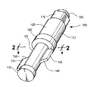
Description dune enclume pourvue dailes ayant une surface supplémentaire comparativement aux enclumes de clé à chocs de la technique antérieure. Les ailes viennent en contact avec des marteaux respectifs dans un sens radial et se chevauchent les unes les autres dans un sens axial en travers de linterface entre les deux marteaux. Chacun de ces derniers peut comprendre un évidement de manière quune aile ne puisse pas venir en contact avec le marteau associé à lautre aile. Dans un mode de réalisation, la surface de laile peut être inclinée pour augmenter la quantité de matière sétendant au-dessus de linterface des marteaux.


Abrégé anglais

An anvil is disclosed having wings with additional surface area compared to prior art impact wrench anvils. The wings engage respective hammers in a radial direction, and overlap with one another in an axial direction across the interface between the two hammers. The hammers can each include a recess so that one wing does not engage the hammer associated with the other wing. In an embodiment, the surface of the wing can be angled to increase the amount of material extending over the hammer interface.

Revendications

Note : Les revendications sont présentées dans la langue officielle dans laquelle elles ont été soumises.


Claims
What is claimed is:
1. A tool for applying an impact force to a work piece, the tool
comprising:
an anvil having an axial shaft rotatable about a longitudinal axis;
first and second hammers rotatable about the shaft and disposed proximate one
another along a hammer interface, each of the first and second hammers
including a
recess; and
first and second wings laterally disposed on and extending radially from the
shaft,
the first and second wings respectively having first and second surfaces
extending
diagonally in radial and axial directions relative to the shaft, wherein the
first and second
surfaces overlap one another along the hammer interface,
the first and second surfaces are adapted to be respectively disposed in the
recesses of the first and second hammers during rotation of the first and
second
hammers.
2. The tool of claim 1, further comprising a flange circumferentially
disposed around the shaft, wherein the first wing extends axially from the
flange along
the shaft.
3. The tool of claim 1, wherein the second wing extends axially along the
shaft from an end of thereof.
4. The tool of claim 1, further comprising an impact head disposed
proximate an end of the shaft and adapted to provide the impact force to the
work piece.
5. An anvil for applying an impact force to a work piece, the anvil
engageable by first and second hammers disposed proximate one another along a
hammer interface and rotating about the anvil, each of the first and second
hammers
including a recess, the anvil comprising:
8

an axial shaft rotatable about a longitudinal axis; and
first and second wings extending radially from the shaft in an axial direction
along the shaft, the first and second wings respectively having first and
second surfaces
extending diagonally in radial and axial directions relative to the shaft,
wherein the first
and second surfaces overlap one another along the hammer interface thereby
creating
respective first and second overlapping surfaces adapted to be respectively
disposed in
the recesses of the first and second hammers during rotation of the first and
second
hammers.
6. The anvil of claim 5, further comprising a flange circumferentially
disposed around the shaft, wherein the first wing axially extends from the
flange along
the shaft.
7. The anvil of claim 5, wherein the second wing extends axially along the
shaft from an end of thereof.
8. The anvil of claim 5, further comprising an impact head disposed
proximate an end of the shaft and adapted to provide the impact force to the
work piece.
9

Description

Note : Les descriptions sont présentées dans la langue officielle dans laquelle elles ont été soumises.


CA 02850899 2016-02-10
Impact Wrench Anvil
Technical Field of the Invention
The present application relates to anvils for impact wrenches. More
particularly,
the present application relates to an anvil having impact wings with increased
material to
improve resistance to fatigue.
Background of the Invention
Impact wrenches are commonly used to remove work pieces, such as threaded
fasteners, from a working material. A motor drives the hammer rotationally by
initiating
quick pulses of power, either through electrical, pneumatic or other means.
The anvil,
which is disposed interior of the impact wrench, includes wings that interact
with the
hammers and transfer the impacting force from the hammers to the work piece.
For
example, a first wing on the anvil can engage a first hammer, and a second
wing spaced
axially from the first wing can engage a second hammer. The wings each engage
their
respective hammer approximately every 360 degrees of rotation.
Current impact wrench anvils include wings with rectangular surfaces, such as
that shown in Fig. 7. The anvil 700 of Fig. 7 includes a first wing 705 with a
first surface
710, and a second wing 715 with a second surface 720. The two surfaces 710,
720 are
rectangular and do not overlap one another in a circumferential or axial
direction. In
other words, the first and second surfaces 710, 720 are diametrically opposed
and axially
spaced relative to each other. That is, the first wing 705 is adapted to
engage a first
hammer, and the second wing 715 is adapted to engage a second hammer. If the
wings
1

CA 02850899 2014-05-02
705, 715 axially overlapped with one another, the first wing would engage the
second
hammer, and the second wing would engage the first hammer which would prevent
the
hammers from rotating relative to the anvil.
Summary of the Invention
The present application discloses an anvil for an impact wrench with wings
having greater impact resistance to the current anvils, thus increasing the
tool's reliability
and usable life. To achieve this, the anvil of the present application
increases the amount
of material on the wing by overlapping the wings with one another across the
interface
between the two hammers. The hammers can each include a recess so that one
overlapping wing does not engage the other wing's hammer. In an embodiment,
the
surface of the wing can also be angled to increase the amount of material
extending over
the hammer interface to improve strength.
In particular, the present application discloses a tool for applying an impact
force
to a work piece, the tool including an anvil having a shaft extending in an
axial direction
and rotatable in a radial direction, first and second hammers each adapted
to rotate
about the shaft and being disposed proximate one another along a hammer
interface, and
first and second wings laterally disposed on the shaft and extending in the
axial direction,
the first and second wings overlapping one another in the axial direction
across the
hammer interface to define respective first and second overlapping portions,
wherein the
first and second hammers each defines a recess adapted to receive the first
and second
overlapping portions, respectively, during rotation of the first and second
hammers.
Also disclosed is an anvil for applying an impact force to a work piece, the
anvil
adapted to be engaged by first and second hammers disposed proximate one
another
along a hammer interface and rotating about the anvil, the anvil including a
shaft
extending in an axial direction and rotatable in a radial direction, first and
second wings
2

CA 02850899 2014-05-02
, =
disposed on the shaft and extending in the axial direction along the shaft,
the first and
second wings overlapping one another in the axial direction across the hammer
interface
to define respective first and second overlapping portions.
Brief Description of the Drawings
For the purpose of facilitating an understanding of the subject matter sought
to be
protected, there are illustrated in the accompanying drawings embodiments
thereof, from
an inspection of which, when considered in connection with the following
description,
the subject matter sought to be protected, its construction and operation, and
many of its
advantages should be readily understood and appreciated.
FIG. 1 is a perspective side view of an anvil for an impact wrench in
accordance
with an embodiment of the present application.
FIG. 2 is a magnified side view of a portion of an anvil in accordance with an
embodiment of the present application.
FIG. 3 is a side cross-sectional view of an anvil located within an impact
wrench
in accordance with an embodiment of the present application.
FIG. 4 is a top plan view of a hammer for use with an impact wrench in
accordance with an embodiment of the present application.
FIG. 5 is a top plan view of an anvil and hammers removed from an impact
wrench and disassembled in accordance with an embodiment of the present
application.
FIG. 6 is a side cross-sectional view of an anvil located within an impact
wrench
in accordance with an embodiment of the present application.
FIG. 7 is a perspective side view of a prior art anvil adapted for use with an
impact wrench.
It should be understood that the comments included in the notes as well as the
materials, dimensions and tolerances discussed therein are simply proposals
such that
3

CA 02850899 2014-05-02
= ,
one skilled in the art would be able to modify the proposals within the scope
of the
present application.
Detailed Description of the Embodiments
While this invention is susceptible of embodiments in many different forms,
there
is shown in the drawings, and will herein be described in detail, a preferred
embodiment
of the invention with the understanding that the present disclosure is to be
considered as
an exemplification of the principles of the invention and is not intended to
limit the broad
aspect of the invention to embodiments illustrated.
The present application discloses an anvil for an impact wrench having wings
with additional material as compared to current prior art wrench anvils. The
anvil of the
present application includes wings adapted to engage respective hammers in a
radial
direction, and that overlap with one another across the interface between the
two
hammers. The hammers can each include a recess where one overlapping wing does
not
engage the hammer associated with the other overlapping wing. In an
embodiment, the
surface of the wing can also be angled, thereby increasing the amount of
material
extending over the hammer interface to better absorb the impact force on the
wing.
As shown in FIGS. 1 and 2, the anvil 100 includes a first end 105 and a second
end 110 opposite the first end. An impact head 115 can be located proximate
the first
end 105 and can be coupled to a base 120 of the anvil 100 in an axial
direction. A shaft
125 can be disposed between the second end 110 and a circumferential flange
130. A
first wing 135 with a first surface 140 and a second wing 145 with a second
surface 150
can also be located along the shaft 125, for example, extending axially along
the shaft
125. In an embodiment, the first wing 135 can extend from the flange 130 and
the
second wing 145 can extend along the second end 110. As shown in FIG. 3, the
anvil
4

CA 02850899 2014-05-02
, *
100 can be disposed within a tool 300, such as an impact wrench, and be
axially and
rotatably movable within the tool 300.
The first and second wings 135, 145 can overlap with one another in the axial
direction. For example, as shown in FIG. 3, the first and second wings 135,
145 can be
disposed proximate the first and second hammers 155, 160, respectively, and
can receive
impacting force from the first and second hammers 155, 160 and transfer the
impacting
force to the work piece in a well-known manner. In an embodiment, the first
and second
hammers 155, 160 border each other at a hammer interface 165 and the first and
second
wings 135, 145 can extend across the hammer interface 165 to provide more
material for
the wings 135, 145 as compared to prior anvil wings. That is, prior art anvil
wings only
extend to the interface and have a flat or rectangular surface interface, and
therefore lack
the additional material that the present application provides to the first and
second wings
135, 145. This additional material provides added fatigue resistance to the
first and
second 135, 145 wings as compared to prior art anvil wings, by providing
better impact
force distribution. The portion of the wings 135, 145 extending across the
hammer
interface 165 can be herein referred to as the first and second overlapping
portions,
respectively.
To account for the added overlapping material, the first and second hammers
155,
160 can respectively include first and second recesses 170, 175. The recesses
170, 175
allow for the overlapping wings 135, 145 to extend across the hammer interface
165
without the overlapping portions simultaneously engaging the rotating hammers
155,
160. For example, as shown in FIG. 3, the first hammer 155 is adapted to
rotate relative
to the first wing 135 and engages the first wing 135 once per rotation.
However, even
though the second wing 145 crosses over the hammer interface 165, the first
recess 170
5

CA 02850899 2014-05-02
. j,
provides adequate clearance so that the second wing 145 does not engage the
first
hammer 155, and only engages the second hammer 160.
FIG. 4 illustrates a hammer 155, 160 in accordance with an embodiment of the
present application, and FIG. 5 illustrates the hammers 155, 160 in exploded
view
proximate the anvil, with the anvil 100 and hammer 155, 160 disassembled and
removed
from the tool. As shown, the hammers 155, 160 are similarly shaped and sized,
and can
include a recess 170, 175 adapted to receive the overlapping portions of the
first and
second wings 135, 145 that extend across the hammer interface 165 to provide
the wings
135, 145 with more material as compared to prior art anvil wings. The hammer
155, 160
can also include a perimeter 180 extending in an elliptical, circular, or
otherwise arcuate
manner, or in any other shape. The perimeter 180 and recess 170, 175
cooperatively
define an opening 185 having one or more receiving areas 190 for receiving the
wings
135, 145 when the hammers 155, 160 rotate about the wings 135, 145.
Although the first and second surfaces 140, 150 can be any shape, they are
shown
in FIGS. 1-5 as being angled or slanted relative to the shaft 125. It has been
discovered
that, many times, fatigue-related failure occurs at the root of the
rectangular-faced wings
in prior art anvils. However, the angled or slanted surfaces 140, 150 of the
present
application add additional material to the wings 135, 145 and, due to their
shape, are
stronger than prior art anvil wings.
FIG. 6 illustrates an embodiment of the present application similar to that
shown
in FIGS. 1-5, with like features represented by like numerals. As shown in
FIG. 6, the
surfaces 140, 150 of the present invention need not be slanted, but can be
surfaces 640,
650 that are orthogonal relative to the shaft 625 and that overlap a hammer
interface 665.
The hammers 655, 660 can include corresponding recesses to account for the
overlapping portion of the wings 635, 645. The rectangular surface 640, 650
shown in
6

CA 02850899 2014-05-02
4 = "
FIG. 6 is advantageous by allowing added material and mass to the wings 635,
645 as
compared to the angle embodiment of FIGS. 1-5.
The matter set forth in the foregoing description and accompanying drawings is
offered by way of illustration only and not as a limitation. While particular
embodiments
have been shown and described, it will be apparent to those skilled in the art
that changes
and modifications may be made without departing from the broader aspects of
applicants' contribution. The actual scope of the protection sought is
intended to be
defined in the following claims when viewed in their proper perspective based
on the
prior art.
7

Dessin représentatif
Une figure unique qui représente un dessin illustrant l'invention.
États administratifs

2024-08-01 : Dans le cadre de la transition vers les Brevets de nouvelle génération (BNG), la base de données sur les brevets canadiens (BDBC) contient désormais un Historique d'événement plus détaillé, qui reproduit le Journal des événements de notre nouvelle solution interne.

Veuillez noter que les événements débutant par « Inactive : » se réfèrent à des événements qui ne sont plus utilisés dans notre nouvelle solution interne.

Pour une meilleure compréhension de l'état de la demande ou brevet qui figure sur cette page, la rubrique Mise en garde , et les descriptions de Brevet , Historique d'événement , Taxes périodiques et Historique des paiements devraient être consultées.

Historique d'événement

Description Date
Représentant commun nommé 2019-10-30
Requête pour le changement d'adresse ou de mode de correspondance reçue 2018-01-12
Accordé par délivrance 2017-01-17
Inactive : Page couverture publiée 2017-01-16
Inactive : Taxe finale reçue 2016-12-06
Préoctroi 2016-12-06
Un avis d'acceptation est envoyé 2016-07-21
Lettre envoyée 2016-07-21
Un avis d'acceptation est envoyé 2016-07-21
Inactive : Approuvée aux fins d'acceptation (AFA) 2016-07-18
Inactive : Q2 réussi 2016-07-18
Modification reçue - modification volontaire 2016-02-10
Inactive : Dem. de l'examinateur par.30(2) Règles 2015-08-10
Inactive : Rapport - Aucun CQ 2015-08-07
Inactive : Page couverture publiée 2014-11-24
Demande publiée (accessible au public) 2014-11-17
Inactive : CIB attribuée 2014-06-03
Inactive : CIB en 1re position 2014-06-03
Lettre envoyée 2014-05-20
Inactive : Certificat de dépôt - RE (bilingue) 2014-05-20
Demande reçue - nationale ordinaire 2014-05-15
Toutes les exigences pour l'examen - jugée conforme 2014-05-02
Exigences pour une requête d'examen - jugée conforme 2014-05-02
Inactive : Pré-classement 2014-05-02

Historique d'abandonnement

Il n'y a pas d'historique d'abandonnement

Taxes périodiques

Le dernier paiement a été reçu le 2016-04-22

Avis : Si le paiement en totalité n'a pas été reçu au plus tard à la date indiquée, une taxe supplémentaire peut être imposée, soit une des taxes suivantes :

  • taxe de rétablissement ;
  • taxe pour paiement en souffrance ; ou
  • taxe additionnelle pour le renversement d'une péremption réputée.

Les taxes sur les brevets sont ajustées au 1er janvier de chaque année. Les montants ci-dessus sont les montants actuels s'ils sont reçus au plus tard le 31 décembre de l'année en cours.
Veuillez vous référer à la page web des taxes sur les brevets de l'OPIC pour voir tous les montants actuels des taxes.

Historique des taxes

Type de taxes Anniversaire Échéance Date payée
Requête d'examen - générale 2014-05-02
Taxe pour le dépôt - générale 2014-05-02
TM (demande, 2e anniv.) - générale 02 2016-05-02 2016-04-22
Taxe finale - générale 2016-12-06
TM (brevet, 3e anniv.) - générale 2017-05-02 2017-05-01
TM (brevet, 4e anniv.) - générale 2018-05-02 2018-04-30
TM (brevet, 5e anniv.) - générale 2019-05-02 2019-04-26
TM (brevet, 6e anniv.) - générale 2020-05-04 2020-04-24
TM (brevet, 7e anniv.) - générale 2021-05-03 2021-04-23
TM (brevet, 8e anniv.) - générale 2022-05-02 2022-04-22
TM (brevet, 9e anniv.) - générale 2023-05-02 2023-04-28
TM (brevet, 10e anniv.) - générale 2024-05-02 2024-04-26
Titulaires au dossier

Les titulaires actuels et antérieures au dossier sont affichés en ordre alphabétique.

Titulaires actuels au dossier
SNAP-ON INCORPORATED
Titulaires antérieures au dossier
RICH D. BOTHMANN
Les propriétaires antérieurs qui ne figurent pas dans la liste des « Propriétaires au dossier » apparaîtront dans d'autres documents au dossier.
Documents

Pour visionner les fichiers sélectionnés, entrer le code reCAPTCHA :


Pour visualiser une image, cliquer sur un lien dans la colonne description du document. Pour télécharger l'image (les images), cliquer l'une ou plusieurs cases à cocher dans la première colonne et ensuite cliquer sur le bouton "Télécharger sélection en format PDF (archive Zip)" ou le bouton "Télécharger sélection (en un fichier PDF fusionné)".

Liste des documents de brevet publiés et non publiés sur la BDBC .

Si vous avez des difficultés à accéder au contenu, veuillez communiquer avec le Centre de services à la clientèle au 1-866-997-1936, ou envoyer un courriel au Centre de service à la clientèle de l'OPIC.


Description du
Document 
Date
(aaaa-mm-jj) 
Nombre de pages   Taille de l'image (Ko) 
Dessin représentatif 2014-10-29 1 8
Abrégé 2014-05-01 1 13
Description 2014-05-01 7 282
Dessins 2014-05-01 4 85
Revendications 2014-05-01 2 65
Description 2016-02-09 7 273
Revendications 2016-02-09 2 53
Paiement de taxe périodique 2024-04-25 24 977
Accusé de réception de la requête d'examen 2014-05-19 1 175
Certificat de dépôt 2014-05-19 1 205
Rappel de taxe de maintien due 2016-01-04 1 111
Avis du commissaire - Demande jugée acceptable 2016-07-20 1 163
Demande de l'examinateur 2015-08-09 3 213
Modification / réponse à un rapport 2016-02-09 11 302
Taxe finale 2016-12-05 1 49