Note : Les descriptions sont présentées dans la langue officielle dans laquelle elles ont été soumises.
CA 02851183 2014-04-04
WO 2013/057613
PCT/1B2012/055304
WING LOCKING ASSEMBLY FOR AN AGRICULTURAL
IMPLEMENT
CROSS REFERENCE TO RELATED APPLICATION
[0001] This application claims priority from and the benefit of U.S. Patent
Application Serial No. 13/277,689, entitled "WING LOCKING ASSEMBLY FOR
AN AGRICULTURAL IMPLEMENT", filed October 20, 2011, which is hereby
incorporated by reference in its entirety.
BACKGROUND
[0002] The invention relates generally to an agricultural implement and,
more
particularly, to a wing locking assembly for an agricultural implement.
[0003] Certain agricultural implements (e.g., planters, seeders, etc.)
include a
center section and one or more wing sections extending laterally outward from
the
center section. In such implements, the wing sections may be pivotally coupled
to the
center section such that the wing sections may be transitioned between a
lowered
transport position and a raised working position. In certain configurations,
an
actuating cylinder extending between the center section and each wing section
facilitates movement of each wing section between the transport and working
positions. Specifically, a first end of the actuating cylinder is pivotally
coupled to a
frame of the wing section, and a second end of the actuating cylinder is
coupled to a
frame of the center section. In certain embodiments one of the couplings may
be
disposed within a slot on the wing or center section. The slot facilitates
free
movement of one end of the actuating cylinder, thereby enabling the wing
section to
pivot relative to the center section during field operation. Consequently, the
wing
sections may adjust to uneven ground surfaces while the implement is moving
through a field, even without active hydraulic control. Unfortunately, this
may allow
one end of the actuating cylinder to slip and fall a short distance while the
wing
section is being folded into or unfolded from transport position. For example,
when
the center of gravity of a wing section passes over a hinge line, the wing
section may
free fall for a short distance within the slot. Such a fall may cause
increased wear of
1
CA 02851183 2014-04-04
WO 2013/057613
PCT/1B2012/055304
the wing section components, or even structural harm. In certain
configurations it is
possible to geometrically orient the slot to prevent free fall, but this can
become
difficult or not feasible as the angle of wing fold increases (e.g., when the
implement
is designed to reduce its transport height).
BRIEF DESCRIPTION
[0004] In one embodiment, an agricultural implement includes a first frame
section
and a bracket mounted to the first frame section. The bracket includes a slot.
The
implement also includes a second frame section pivotally coupled to the first
frame
section and a cam mounted to the second frame section. The implement includes
an
actuating cylinder having a first end pivotally coupled to the second frame
section,
and a second end disposed within the slot. The actuating cylinder is
configured to
induce the second frame section to rotate between a raised transport position
and a
lowered working position. The implement also includes a locking mechanism
rotatably coupled to the bracket. The locking mechanism includes a first end
configured to engage the second end of the actuating cylinder, and a second
end
configured to abut the cam. The locking mechanism is configured to drive the
second
end of the actuating cylinder into a desired position within the slot upon
contact
between the cam and the second end of the locking mechanism.
[0005] In another embodiment, an agricultural implement includes a first
toolbar
and a second toolbar pivotally coupled to one another. The implement also
includes
an actuating cylinder having a first end pivotally coupled to the second
toolbar, and a
second end disposed within a slot in a bracket of the first toolbar. The
actuating
cylinder is configured to drive the second toolbar to rotate between a raised
transport
position and a lowered working position, and the second end of the actuating
cylinder
is configured to move within the slot. The implement includes a locking
mechanism
rotatably coupled to the bracket of the first toolbar, and configured to drive
the second
end of the actuating cylinder into a desired position within the slot upon
contact
between a cam of the second toolbar and the locking mechanism.
2
CA 02851183 2014-04-04
WO 2013/057613
PCT/1B2012/055304
[0006] In another embodiment, an agricultural implement includes a first
toolbar
having a slot and a second toolbar pivotally coupled to the first toolbar. The
implement also includes an actuating cylinder having a first end pivotally
coupled to
the second toolbar, and a second end disposed within the slot. The actuating
cylinder
is configured to induce the second toolbar to rotate between a raised
transport position
and a lowered working position. The implement includes a locking assembly
having
a cam coupled to the second toolbar, and a locking mechanism rotatably coupled
to
the first toolbar. The locking mechanism is configured to drive the second end
of the
actuating cylinder into a desired position within the slot upon contact
between the
cam and the locking mechanism.
DRAWINGS
[0007] These and other features, aspects, and advantages of the present
invention
will become better understood when the following detailed description is read
with
reference to the accompanying drawings in which like characters represent like
parts
throughout the drawings, wherein:
[0008] FIG. 1 is a perspective view of a towable agricultural implement
employing
an embodiment of a wing locking assembly;
[0009] FIG. 2 is a rear view of the towable agricultural implement of FIG.
1;
[0010] FIG. 3 is a detailed rear view of a first wing section of the
towable
agricultural implement of FIG. 1, illustrating an embodiment of a wing locking
assembly;
[0011] FIG. 4 is a detailed rear view of the first wing section of FIG. 3,
illustrating
the first wing section partially folded;
[0012] FIG. 5 is a detailed rear view of the first wing section of FIG. 3,
illustrating
the first wing section folded near a transport position; and
3
CA 02851183 2014-04-04
WO 2013/057613
PCT/1B2012/055304
[0013] FIG. 6 is a detailed rear view of a first wing section of the
towable
agricultural implement of FIG. 1, illustrating another embodiment of a wing
locking
assembly.
DETAILED DESCRIPTION
[0014] FIG. 1 is a perspective view of a towable agricultural implement 10
employing an embodiment of a wing locking assembly. The implement 10 includes
a
center section 12, a first wing section 14, and a second wing section 16. Each
section
is configured to support multiple ground engaging tools, such as openers, row
units
and/or coulters. In the illustrated embodiment, the center section 12 includes
a center
toolbar 18 that forms a portion of a frame for attaching the ground engaging
tools.
The first wing section 14 and the second wing section 16 are rotatably coupled
to the
center wing section 12, thereby enabling the wing sections 14 and 16 to follow
the
contours of a field while the wing sections are in the illustrated working
position. As
discussed in detail below, the first and second wing sections are also
configured to
transition to a transport portion that substantially decreases the width of
the
implement 10.
[0015] The first wing section 14 includes a first wing toolbar 20 that
forms a
portion of a frame for attaching ground engaging tools. As shown, an actuating
cylinder 22 extends between the first wing toolbar 20 and the center toolbar
18. The
actuating cylinder 22 includes a piston rod 24 that may be hydraulically or
pneumatically controlled, for example. A first end of the actuating cylinder
22 is
pivotally coupled to the first wing toolbar 20, and a second end is coupled to
the
center toolbar 18. In this configuration, the piston rod 24 may be extended to
drive
the first wing section 14 toward the illustrated working position, and
retracted to drive
the first wing section 14 toward a folded/raised transport position.
[0016] The second wing section 16 is configured much like the first wing
section
14. The second wing section 16 includes a second wing toolbar 26 that forms a
portion of a frame for attaching ground engaging tools. A second actuating
cylinder
28 extends between the second wing toolbar 26 and the center toolbar 18. The
4
CA 02851183 2014-04-04
WO 2013/057613
PCT/1B2012/055304
actuating cylinder 28 includes a piston rod 30 that may be hydraulically or
pneumatically controlled, for example. A first end of the actuating cylinder
28 is
pivotally coupled to the second wing toolbar 26, and a second end is coupled
to the
center toolbar 18. In this configuration, the piston rod 30 may be extended to
drive
the second wing section 16 toward the illustrated working position, and
refracted to
drive the second wing section 16 toward a folded/raised transport position. In
the
illustrated embodiment, the center section 12 is coupled to a tow bar 32,
including a
hitch 34. The hitch 34 may, in turn, be coupled to a tractor, or other tow
vehicle, such
that the towable agricultural implement 10 may be pulled through a field.
[0017] As discussed in detail below, each wing section 14 and 16 includes a
wing
locking assembly. The wing locking assemblies enable the wing sections 14 and
16
to rotate relative to the center section 12 while the wing sections 14 and 16
are in the
illustrated working position, thereby enabling the wing sections 14 and 16 to
follow
the contours of uneven surfaces of the field. To facilitate rotation of the
wing sections
14 and 16, the piston rods 24 and 30 are attached to slots within the center
section 12,
thereby enabling the second end of each actuating cylinder to move within a
respective slot. When the wing sections 14 and 16 are rotated from the
illustrated
working position to a raised transport position, each locking assembly blocks
movement of the second end of each actuating cylinder within the respective
slot,
thereby substantially reducing unwanted movement of the wing sections. Such a
locking mechanism blocks the wing sections 14 and 16 from free falling during
the
transition from the lowered working position to the raised transport position.
[0018] FIG. 2 is a rear view of the towable agricultural implement 10 of
FIG. 1
with an embodiment of a wing locking assembly. A first wing locking assembly
35
includes a locking mechanism which is located behind a first rear bracket 36.
The
first rear bracket 36 is coupled to the center toolbar 18, and includes a slot
38.
Although the slot 38 is curved in the illustrated embodiment, it should be
appreciated
that the slot 38 may be otherwise contoured in alternative embodiments. For
example, the slot 38 may be straight and horizontal, the slot 38 may be
straight and
vertical, the slot 38 may be straight and angled, the slot 38 may include
straight and/or
rounded portions, or the slot 38 may be any other suitable shape. As
illustrated, an
CA 02851183 2014-04-04
WO 2013/057613
PCT/1B2012/055304
end 40 of the piston rod 24 is disposed within to the slot 38. In this
configuration, the
end 40 of the piston rod 24 may move within the slot 38 as the implement 10
traverses
a field. As such, the first wing section 14 may rotate relative to the center
section 12
based on the terrain. The first wing locking assembly 35 includes a cam 42
coupled
to the first wing toolbar 20. The cam 42 is rotatably, or pivotally, coupled
to the first
rear bracket 36 via a fastener 44. Thus, the first wing section 14 may pivot
about the
fastener 44 as the end 40 of the piston rod 24 moves within the slot 38. In
alternative
embodiments, the actuating cylinder 22 may be pivotally coupled to the center
toolbar
18, and the slot 38 may be located within the first wing section 14. In such
embodiments, the cam 42 may be coupled to the center section 12.
[0019] As discussed in greater detail below, when the first wing section 14
is
rotated from the lowered working position to the raised transport position,
the first
wing locking assembly 35 controls the movement of the second end 40 of the
actuating cylinder 22 within the slot 38. Specifically, the first wing toolbar
20 and the
cam 42 rotate about the fastener 44 as the piston rod 24 retracts. The cam 42
then
engages a locking mechanism, thereby inducing the locking mechanism to hold
the
second end 40 of the actuating cylinder in a desired position within the slot
38. As a
result, rotation of the first wing section 14 relative to the center section
12 is blocked,
thereby substantially reducing the possibility of free fall that may otherwise
occur
when the center of gravity of the wing section passes over a hinge line.
[0020] Much like the first wing locking assembly 35, a second wing locking
assembly 45 includes a locking mechanism which is located behind a second rear
bracket 46. The second rear bracket 46 is coupled to the center toolbar 18,
and
includes a slot 48. As illustrated, an end 50 of the piston rod 30 is disposed
within the
slot 48. In this configuration, the end 50 of the piston rod 30 may move
within the
slot 48 as the implement 10 traverses a field. As such, the second wing
section 16
may rotate relative to the center section 12 based on the terrain. The second
wing
locking assembly 35 includes a cam 52 coupled to the second wing toolbar 26.
The
cam 52 is rotatably, or pivotally, coupled to the second rear bracket 46 via a
fastener
54. Thus, the second wing section 16 may pivot about the fastener 54 as the
end 50 of
the piston rod 30 moves within the slot 48. In alternative embodiments, the
actuating
6
CA 02851183 2014-04-04
WO 2013/057613
PCT/1B2012/055304
cylinder 28 may be coupled to the center toolbar 18, and the slot 48 may be
located
within the second wing section 16. In such embodiments, the cam 52 may be
coupled
to the center section 12.
[0021] Again, the second wing section 16 functions much like the first wing
section 14. For example, when the second wing section 16 is rotated from the
lowered working position to the raised transport position, the second wing
locking
assembly 45 controls the movement of the second end 50 of the actuating
cylinder in
a desired position within the slot 48. Specifically, the second wing toolbar
26 and the
cam 52 rotate about the fastener 54 as the piston rod 30 retracts. The cam 52
then
engages a locking mechanism, thereby inducing the locking mechanism to hold
the
second end 50 of the actuating cylinder in a desired position within the slot
48. As a
result, rotation of the second wing section 16 relative to the center section
12 is
blocked, thereby substantially reducing the possibility of free fall that may
otherwise
occur when the center of gravity of the wing section passes over a hinge line.
[0022] It should be noted that the term "toolbar" as used herein may be
interpreted
broadly to include the complete frame structure of a section. For example, the
center
section 12 includes the toolbar 18, the first wing section 14 includes the
first wing
toolbar 20, and the second wing section 16 includes the second wing toolbar
26. The
"toolbar" (e.g., toolbar 18, 20, and 26) may include one or more brackets
(e.g., rear
brackets 36 and 46), locking assemblies 35 and 45, cams 42 and 52, or any
other
similar structure. The tool bars may also form a portion of a frame of each
section.
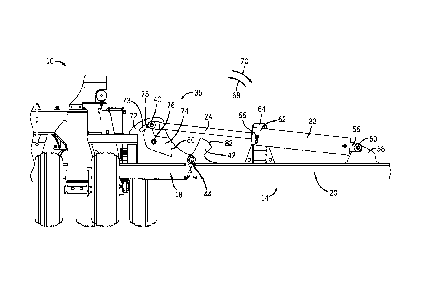
[0023] FIG. 3 is a detailed rear view of the first wing section 14 of the
towable
agricultural implement 10 of FIG. 1, illustrating an embodiment of the wing
locking
assembly 35. The actuating cylinder 22 includes a mounting end 56, which is
pivotally coupled to a bracket 58 by a fastener 60. The bracket 58 is attached
to the
first wing toolbar 20. In addition, the actuating cylinder 22 includes an end
62 located
on an opposite side from the mounting end 56, adjacent to support 64. At end
62, the
piston rod 24 is attached to the actuating cylinder 22 using a hydraulic
fitting 66. As
previously discussed, the piston rod 24 may extend and retract to facilitate
rotation of
the first wing toolbar 20 relative to the center toolbar 18. For example, the
piston rod
7
CA 02851183 2014-04-04
WO 2013/057613
PCT/1B2012/055304
24 may retract to drive the first wing section 14 to rotate in a direction 68
toward a
raised transport position. Conversely, the piston rod 24 may extend to drive
the first
wing section 14 to rotate in a direction 70 toward the illustrated working
position.
[0024] As illustrated, the first rear bracket 36 has been omitted from FIG.
3 to
show other parts of the first wing locking assembly 35. In particular, a front
bracket
72 is coupled to the center toolbar 18, and includes a slot 73. The end 40 of
the piston
rod 24 (i.e., second end of the actuating cylinder 22) is disposed within to
the slot 73,
and the slot 38 of the bracket 36, thereby enabling the piston rod 24 to move
relative
to the brackets 72 and 36. The first wing locking assembly 35 includes a
locking
mechanism or member 74. The locking mechanism 74 is rotatably coupled to the
front bracket 72 and to the first rear bracket 36 via a fastener 76. The
fastener 76
facilitates rotational motion of the locking mechanism 74, thereby enabling a
holding
end 78 of the locking mechanism to move along the slot 73. In certain
embodiments,
a bushing or bearing may be disposed about the fastener 76 to facilitate
rotation of the
locking mechanism 74. The holding end 78 is rotatably coupled to the end 40 of
the
piston rod 24 with a fastener. In the illustrated embodiment, the holding end
78 is
rounded, or o-shaped, to enable the fastener 76 to be inserted within the end
78.
However, in other embodiments, the holding end 78 may be c-shaped, u-shaped,
or
any other suitable shape. In such embodiments, the end 78 may cradle the end
40 of
the piston rod 24 without necessarily being fastened to it.
[0025] The locking mechanism 74 has a locking end 80 configured to abut an
end
82 of the cam 42. In certain embodiments, the locking end 80 may include
rollers to
enable smooth contact between the locking end 80 and the cam 42. In certain
embodiments, the locking end 80 may be substantially u-shaped and configured
to
engage a substantially c-shaped cam 42. When the first wing section 14 is
rotated
from the illustrated working position in the direction 68, the first wing
section 14
rotates around the fastener 44. As the first wing section 14 rotates, the cam
end 82
engages the locking end 80, thereby driving the locking mechanism 74 to hold
the end
40 of the piston rod 24 in a desired position (e.g., against the end of the
slot 73).
Thus, the end 40 of the piston rod 24 is blocked from free falling within the
slot 73
during the transition from the lowered working position to the raised
transport
8
CA 02851183 2014-04-04
WO 2013/057613
PCT/1B2012/055304
position, thereby substantially reducing wear and loading on the wing section
components.
[0026] FIG. 4 is a detailed rear view of the first wing section 14 of FIG.
3,
illustrating the first wing section 14 partially folded. As illustrated, the
first wing
toolbar 20 is rotated approximately 45 degrees from the working position
illustrated in
FIG. 3. The cam end 82 is near the locking end 80 but not abutting the locking
end
80. FIG. 5 is a detailed rear view of the first wing section 14 of FIG. 3,
illustrating
the first wing section 14 folded near a transport position. In this figure,
the first wing
toolbar 20 is rotated approximately 100 degrees from the working position
illustrated
in FIG. 3. The cam end 82 abuts the locking end 80, thereby holding the end 40
of the
piston rod 24 against the end of the slot 73. Therefore, the first wing
section 14 is
locked in place to inhibit the wing section 14 from free falling within the
slot 73.
[0027] As the piston rod 24 is retracted into the actuating cylinder 22,
the end 40
of the piston rod 24 is pulled to the end of the slot 73 closest to the first
wing section
14. As a result, the first wing toolbar 20 rotates from a generally horizontal
position
(i.e., approximately 0 degrees) toward a vertical position. (i.e.,
approximately 90
degrees). The first wing toolbar 20 rotates along a pivot, or hinge line,
created where
the fastener 44 couples the first wing toolbar 20 to the center toolbar 18.
When the
center of gravity of the wing section 14 passes over the hinge line, the
weight of the
wing section 14 drives the end 40 of the piston rod 24 to move within the slot
73.
Therefore, without the locking mechanism 74, the end 40 of the piston rod 24
may
move within the slot 73 (e.g., the first wing section 14 may free fall a short
distance).
However, in the illustrated embodiment, the locking mechanism 74 holds the end
40
of the piston rod 24 in a desired position (e.g., against the end of the slot
73), thereby
blocking movement of the frame section 14, and facilitating smooth wing
section 14
folding. Furthermore, the shape and size of the slot 73 allows the first wing
section
14 to have a wide range of movement over terrain while the first wing section
14 is in
the working position. While the illustrated configuration facilitates rotation
of the
first wing section through an angle of approximately 130 degrees from the
horizontal
position, it should be appreciated that alternative configurations may enable
the frame
section to rotate through a larger or smaller angle.
9
CA 02851183 2014-04-04
WO 2013/057613
PCT/1B2012/055304
[0028] FIG. 6 is a detailed rear view of the first wing section 14 of FIG.
1,
illustrating another embodiment of a wing locking assembly 35. In the
illustrated
embodiment, a locking mechanism 90 is rotatably coupled to the front bracket
72 by a
fastener 92. In certain embodiments, a bushing or bearing may be disposed
about the
fastener 92 to facilitate rotation of the locking mechanism 90. The locking
mechanism 90 has a holding end 94, which is c-shaped, or u-shaped, and
includes
fingers 96 and 98 to capture the end 40 of the piston rod 24. The locking
mechanism
90 also has a locking end 100 configured to abut the end 82 of the cam 42.
[0029] As the first frame section 14 rotates in the direction 68, the cam
end 82
engages the locking end 100. The force on the locking end 100 urges the
locking
mechanism 90 to rotate, thereby driving the holding end 94 to capture the end
40 of
the piston rod 24. The fingers 96 and 98 press against the end 40 to hold the
end 40 in
a desired position within the slot 73. Therefore, the locking mechanism 90
locks the
first wing section 14 in place to block movement of the first wing section 14
while the
wing section 14 is in the raised transport position. The locking mechanism 90
functions similar to the locking mechanism 74. However, when the first wing
section
14 is in the working position, as illustrated, the locking mechanism 90 does
not
generally interfere with movement of the end 40 of the piston rod 24 as it is
not
connected to the end 40.
[0030] As may be appreciated, the functionality of the first wing section
14
described above in relation to FIGS. 3 through 6 also applies to the second
wing
section 16. Further, while only certain features of the invention have been
illustrated
and described herein, many modifications and changes will occur to those
skilled in
the art. For example, a wing locking assembly may be used between an outer
secondary wing, and a primary inner wing, to allow for multi-fold implements
(e.g., in
an implement that has five sections instead of three). It is, therefore, to be
understood
that the appended claims are intended to cover all such modifications and
changes as
fall within the true spirit of the invention.