Note : Les descriptions sont présentées dans la langue officielle dans laquelle elles ont été soumises.
CA 02851584 2014-04-09
WO 2013/076602
PCT/1B2012/056023
PRESSURE ENHANCED FRACTIONAL TREATMENT AND DRUG
DELIVERY
TECHNICAL FIELD
The present invention relates to fractional tissue treatment and more
particularly, to pressure enhanced fractional treatment and drug delivery
devices.
BACKGROUND OF THE INVENTION
Ablative fractional laser devices have gained acceptance as a preferred method
for skin rejuvenation. Notable improvements in facial rhytides, photodamage,
acne
scarring, skin laxity, to name but a few conditions, are now well known. This
type of
invasive fractional tissue treatment is based on micro holes created (or
"drilled") in a
target tissue using an energy source, such as a laser. Other types of energy
sources are
known to be effective in producing micro holes. Among these sources are:
lasers, as
already mentioned above, micro needles, micro electrodes, cryogenically cooled
micro tips, ultrasound, radio-frequency and others. Each individual hole is
surrounded
by non-damaged tissue. Holes density, i.e. the number of holes per unit of
area, as
well as hole-depth and hole-surrounding coagulated tissue, within the target
tissue
may all vary according to the treatment protocol and clinical objectives.
Although it is relatively straight forward to create or "drill" such holes or
micro-holes for fluid communication, the micro holes tend to collapse after
the
ablation or there is fluid oozing out the micro holes. Therefore, in any of
the prior
art methods it is still a great challenge to control the micro hole dimension
or patency
during its creation and thereafter.
It is, therefore, an aim of the present invention to provide a method and a
device
to alleviate some of the problems of the prior art methods.
BRIEF SUMMARY
One aspect of the invention provides a method of fractional treatment of
tissue. The method comprising: creating at least one micro hole in a target
tissue; and
1
CA 02851584 2014-04-09
WO 2013/076602
PCT/1B2012/056023
either a) applying pressure on said target tissue to decrease the patency of
said at least
one micro hole; administering material and/or fluid and/or drug onto said
target tissue;
releasing said applied pressure on said target tissue to increase the patency
of said at
least one micro hole; and propelling said material and/or fluid and/or drug
into said at
least one micro hole; or b) administering material and/or fluid and/or drug
onto said
target tissue under sub-atmospheric pressure conditions, the patency of said
at least one
micro hole being decreased; increasing the atmospheric pressure to atmospheric
or
above atmospheric conditions to thereby increase the patency of said at least
one micro
hole; and propelling said material and/or fluid/ and/or drug into said at
least one micro
hole.
Another aspect of the invention provides a device for fractional treatment of
tissue, device for fractional treatment of tissue, said device comprising: an
energy
source, wherein said energy source is configured to create at least one micro
hole in a
target tissue; a pressure source, wherein said pressure source is configured
to exert and
release pressure on said target tissue; a reservoir, wherein said reservoir is
configured to
contain material and/or fluid and/or drug and controllably release said
material and/or
fluid and/or drug onto said target tissue; and a controller, wherein said
controller is
configured to control the activation of at least one of said energy source,
said pressure
source and said reservoir.
There is also provided a process or method for ultrasound enhanced fractional
treatment of tissue, the process or method comprising: drilling or creating at
least one
micro hole in a target tissue; allowing a fluid secreted by the target tissue
adjacent to
said at least one hole to penetrate into said at least one hole; applying
ultrasound energy
on said target tissue and secreted fluid, causing the formation of at least
one cavitation
bubble in said secreted fluid; and controlling said at least one hole patency
by
controlling said applied ultrasound characteristics affecting at least one of
the following:
bubble average size; bubbles density; bubble average formation pace; bubble
average
growing pace; bubble average shrinking pace; and bubble exploding pace.
A process or method for ultrasound enhanced fractional treatment of tissue,
may
comprise: drilling or creating at least one hole in a target tissue;
administering a fluid on
said target tissue and allowing said administered fluid to at least partially
penetrate said
2
CA 02851584 2014-04-09
WO 2013/076602
PCT/1B2012/056023
at least one hole; applying ultrasound energy on said target tissue and said
administered
fluid causing the formation of at least one cavitation bubble in said
administered fluid;
and controlling said at least one hole patency by controlling said applied
ultrasound
characteristics affecting at least one of the following: bubble average size;
bubbles
density; bubble average formation pace; bubble average growing pace; bubble
average
shrinking pace; and bubble exploding pace.
In the process, the ultrasound energy is applied approximately perpendicular
to
the surface of said target tissue.
Preferably the ultrasound energy is applied to create surface waves which are
approximately parallel to said surface of said target tissue.
The process may further comprise administering material onto said target
tissue.
In the process the administering of the material may further comprise
administering a fluid.
In the process, the administering of the fluid may further comprise
administering
a drug.
In the process, the administering fluid may further comprise administering a
cosmetic material.
The process may further comprise applying ultrasound energy so that at least
one
hole patency is changing over time and the administered material penetration
pace into
the at least one hole is increased.
The process may further comprise applying an ultrasound energy to cause
cavitation of at least one bubble.
The process may further comprise controlling the at least one bubble
cavitation
pace.
3
CA 02851584 2014-04-09
WO 2013/076602
PCT/1B2012/056023
The process may further comprise controlling the damage of the target tissue.
The process may further comprise administering of an abrasive material.
The process may further comprise applying ultrasound, electrical or optical
energy to activate the abrasive material or material to be delivered.
The abrasive material may be activated by the energy source.
An sonodynamic therapy process for ultrasound enhanced fractional treatment
of tissue, may comprise: drilling or creating at least one hole in a target
tissue;
administering a fluid onto the target tissue and allowing the administered
fluid to at
least partially penetrate the at least one hole; and applying ultrasound
energy on said
target tissue.
In the above process, the administered fluid may comprise a sonosensitizable
agent capable of undergoing an exothermic reaction. In this embodiment, the
fluid
comprises sub-micron particles which serve as cavitation grains. In this
embodiment
the fluid may comprise a silica derivative.
Alternatively the administered fluid may comprise an active ingredient, for
example Amino Levulenic acid or any other photo sensitizer. In this
embodiment, the
fluid causes oxidative impact in the hole and/or on the hole walls, thus
increasing the
patency of the hole.
A therapy process may be a combination of the application of pressure (as
detailed in the first method above) and further the application of ultrasound
energy for
further enhancement of the fractional treatment.
BRIEF DESCRIPTION OF THE DRAWINGS
For a better understanding of embodiments of the invention and to show how
the same may be carried into effect, reference will now be made, purely by way
of
example, to the accompanying drawings in which like numerals designate
4
CA 02851584 2014-04-09
WO 2013/076602
PCT/1B2012/056023
corresponding elements or sections throughout several views.
Figure lA illustrates one conceptual configuration of the present
invention.
Figure 1B illustrates an embodiment in which the energy delivery
mechanism, the pressure applicator and the pressure applicator aperture are
placed over
a target tissue.
Figure 1C illustrates one aspect of the present invention, wherein the
pressure
applicator applies negative pressure over the tissue causing the tissue to be
sucked into
the aperture and hole's patency to be decreased.
Figure 1D illustrates another embodiment of the present invention, once the
patency of the hole is reduced or decreased, the material dispensing element
releases
material into the pressure applicator aperture.
Figure lE depicts a further embodiment of the present invention.
Figures 2A and 2B illustrate one conceptual configuration of the
mechanical grid according to the present invention.
Figure 3 schematically illustrates a high level flowchart according to some
embodiments of the invention.
Figure 4 illustrates one conceptual cavitation bubble management system.
Figure 5 illustrates hole fragmentation (ablation) through bubble cavitation.
The drawings together with the following detailed description make apparent
to those skilled in the art how the invention may be embodied in practice.
DETAILED DESCRIPTION
Prior to setting forth the detailed description, it may be helpful to set
forth
definitions of certain terms that will be used hereinafter.
The term "laser", as used herein, refers to any type of laser ¨ for example:
CA 02851584 2014-04-09
WO 2013/076602
PCT/1B2012/056023
solid state (e.g. Neodymium YAG, Erbium YAG, Holmium YAG, Thulium
or Alexandrite); diode (e.g. in various wavelengths, such as in the range 532-
1600 nm);
gas (e.g. CO2, Argon); or fiber laser (e.g. Neodymium, Erbium, Holmium,
Thulium or
Alexandrite). Furthermore, laser beams referred to in the application may be:
continuous pulsed; long pulsed, short pulsed, Q-switched pulse; or any other
temporal
pattern.
The term "treatment beam", as used, herein, refers to an intense laser beam
transferred through an optical fiber or through air to treat a target tissue.
For example,
the treatment beam may be a pulsed laser beam or any other laser beam as
defined
above. The treatment may be ablative or non-ablative, as determined by the
beam
intensity in respect to a tissue ablation threshold.
The term "fractional treatment", as used herein, refers to a treatment of a
target
tissue or organ in which at least one treatment point, or rather, a micro hole
is created in
the tissue and is surrounded by a non-treated tissue. On a target tissue, one
or more
treatment points may be created in a variety of sizes, depths, patterns and
densities.
Fractional treatment may be invasive, non-invasive or any combination of the
two.
The term "energy source", as used, herein, refers to any energy source
which may create fractional treatment. As non limiting examples for such
energy
sources are: laser; non-coherent light sources; radio frequency generators;
microwave
generators; cryogenically cooled material; ultrasound etc.
The term "patency", as used herein, means the state or quality of being open,
expanded, or unblocked.
The term "cavitation", as used herein, is the formation and then immediate
implosion or explosion of cavities in a liquid ¨ i.e. small liquid-free zones
("bubbles") ¨
that are the consequence of forces acting upon the liquid. This usually occurs
when a
liquid is subjected to rapid changes of pressure that cause the formation of
cavities
where and when the pressure is relatively low.
With specific reference now to the drawings in detail, it is stressed that the
particulars shown are by way of example and for purposes of illustrative
discussion of
the preferred embodiments of the present invention only, and are presented in
the
6
CA 02851584 2014-04-09
WO 2013/076602
PCT/1B2012/056023
cause of providing what is believed to be the most useful and readily
understood
description of the principles and conceptual aspects of the invention. In this
regard, no
attempt is made to show structural details of the invention in more detail
than is
necessary for a fundamental understanding of the invention, the description
taken with
the drawings making apparent to those skilled in the art how the several forms
of the
invention may be embodied in practice.
Before explaining at least one embodiment of the invention in detail, it is to
be
understood that the invention is not limited in its application to the details
of
construction and the arrangement of the components set forth in the following
description or illustrated in the drawings. The invention is applicable to
other
embodiments or of being practiced or carried out in various ways. Also, it is
to be
understood that the phraseology and terminology employed herein is for the
purpose
of description and should not be regarded as limiting.
Figure lA illustrates a high level conceptual configuration of one
embodiment of the present invention. System 1 includes an energy source 20
which is
controlled by control unit 30. Control unit 30 has a user interface 40 which
allows the
user, among other things, to set the working parameters of the system for a
chosen
treatment. Energy delivery mechanism 50 is functionally connected to energy
source 20
and is configured to deliver treatment energy from the energy source 20 to the
target
tissue 60. Different energy sources may require different energy delivery
mechanisms.
Non limiting examples for energy delivery mechanisms are: optical fiber; free
beam
scanner; beam splitters; light guides; micro needles; micro electrodes;
cryogenically
cooled tips; micro transducers etc. All of these systems produce micro holes
in
the tissue that is being treated. Any of these systems, or a combination
thereof,
may be used in the present invention.
The energy delivery mechanism 50 is configured to be placed on or above the
target tissue 60 and to functionally deliver energy from energy source 20 onto
the target
tissue 60 to fractionally treat the tissue. That is, to create micro holes 71
in the tissue
that is to be treated, as shown in figure 1B. As mentioned above the energy
source 20
may comprise any of the systems described above, or a combination thereof.
A pressure applicator 70 contacts the target tissue 60. The pressure
applicator 70 is in fluid communication with a pressure source 75. The
pressure
7
CA 02851584 2014-04-09
WO 2013/076602
PCT/1B2012/056023
source 75 may also be controlled by control unit 30, or it may be controlled
by a separate
controller. It is the application of pressure onto the micro hole which allows
the patency
of the micro hole to be controlled. Energy delivery mechanism 50 and pressure
applicator 70 are configured to work independently and simultaneously on the
same
target tissue 60 so that different pressure levels can be applied on the
target tissue
before, during or after energy delivery mechanism 50 delivers energy to the
target
tissue 60.
In another embodiment of the present invention, the pressure applicator
can be a mechanical instrument which is configured to fold the target tissue
or to
apply lateral pressure which tends to close the at least one hole. Such a
mechanical instrument may be configured in a scissors like or tweezers like
configuration. According to another embodiment of the mechanical pressure
applicator a temperature conditioning mechanism may be integrated in or
coupled to the instrument. A temperature conditioning mechanism may cool or
heat the target tissue in order to affect its mechanical or chemo-kinetic of
the
target tissue.
In one embodiment of the present invention the energy source 20 is a
light source and energy delivery mechanism 50 may be, for example, a scanner,
a
fiber, a light guide or a beam splitter. In this configuration, pressure
applicator 70 may
be a transparent material for the treatment beam wavelength with an aperture
to
contact the target tissue 60. The aperture may apply positive or negative
pressure on
the target tissue.
Alternatively, the administering of the fluid takes place under sub-
atmospheric
pressure, thereafter the treatment tissue is subject to atmospheric or above
atmospheric
pressure, thereby increasing the patency of the hole or holes.
In yet another embodiment of the present invention the energy source may
be an array of micro needles which are configured to reach the target tissue
60 through
pressure applicator 70 while still allowing, simultaneously or consequently,
the
pressure applicator to apply negative or positive pressure on the target
tissue 60,
before, during or after the fractional treatment.
In yet another embodiment an array of cryogenically cooled tips may be
8
CA 02851584 2014-04-09
WO 2013/076602
PCT/1B2012/056023
applied on the target tissue through pressure applicator 70 to create the
micro holes. In
yet a further embodiment of the present invention an array of micro
transducers create
the micro holes in the target tissue.
In the present invention, the system may comprise a reservoir 90 configured
to hold at least one material. The material may be a cosmetic fluid, such as
anti-oxidant, hyaluronic acid or collagen, or other fluid such as a drug,
which
may be, for instance, BotoxTM, used either as a cosmetic treatment or medical
treatment. Reservoir 90 is in fluid communication with the aperture of
pressure applicator 76 through material dispensing element 91. The material
dispensing element 91 may also be controlled by control unit 30. The material
dispensing element may be micro needles, nozzles or other such delivery
system.
Control unit 30 may also control reservoir 90 and monitor its content through
at
least one sensor.
In yet another embodiment of the present invention, an excess fluid removal
unit 100 may be in fluid communication with pressure applicator aperture 76 of
fig. 1B.
In conditions of excess fluid accumulated in the pressure applicator aperture
76,
whether due to over flow from material reservoir 90 or spontaneous fluid
secretion from
the target tissue 60 or holes 71, excess material removal unit will remove
excess fluid.
This is particularly useful when, for instance, the treatment is used for the
removal of
acne spots or boils, where fluid may accumulate in the target treatment area.
Unit 100
may be controlled by control unit 30, or have a separate controller. A fluid
sensor
in the pressure applicator may be controlled by control unit 30, which may
activate
excess material removal unit when excess fluid is detected. A tissue
temperature
conditioning unit may be configured to affect spontaneous fluid secretion.
According to
one embodiment of the present invention the tissue temperature conditioning
unit may
cool the tissue in order to reduce spontaneous secretion.
Figure 1B illustrates an embodiment of the present invention, in which the
energy delivery mechanism 50, pressure applicator 70 and pressure applicator
aperture
76 are placed over the target tissue 60. In this embodiment, the system has
delivered
fractional treatment to underneath the target tissue 60 to create micro holes
71. The
pressure applicator maintains aperture 76 in a condition which allows micro
holes 71 to
be relatively open. In one embodiment, the pressure applicator 70 may comprise
of a
cooling element which reduces the target tissue temperature so that the module
of
9
CA 02851584 2014-04-09
WO 2013/076602
PCT/1B2012/056023
elasticity of the target tissue is effectively reduced, and therefore, the
micro holes do
not tend to collapse. Alternatively, mechanical support, for instance, by
means of a grid,
may be provided. In yet another embodiment of the present invention, the
pressure
applicator may maintain a certain degree of positive pressure over the tissue
so that
the pressure inside the holes is bigger than the pressure applied by the walls
of the
hole and therefore maintain its patency. That is, maintain the opening to the
size
required, such that the injection of the fluid is facilitated.
Referring now to figure 1C, in one embodiment of the present invention, the
pressure applicator applies negative pressure over the tissue, causing the
tissue to be
sucked and inserted into aperture 76 and holes 72 patency to be decreased. A
negative
pressure source 80 may be in fluid communication with pressure applicator
aperture 76.
This treatment may be useful also for the removal of oozing fluids from
ablated holes,
as well as for the treatment of such conditions as acne or boils, where fluid
exists and
further builds up in the target tissue.
In yet another embodiment of the present invention, the target tissue 60
may be pinched by pressure applicator with positive pressure from the sides
causing
similar effect of reducing holes patency. The pressure inside and outside the
holes
determines the degree of patency of the micro holes. As the pressure can be
finely controlled, the present invention is amenable for use in a variety of
tissue
conditions.
Referring now to figure 1D, in another embodiment of the present invention,
once holes patency is reduced, material dispensing element 91 releases
material into
the pressure applicator aperture 76 so that at least part of the target tissue
surface is
covered by the material 110. The material 110 has adequate viscosity level to
be effectively dispensed by dispensing element 91 and has adequate wetting
properties
to cover most of the target tissue surface. The material may incorporate a
therapeutic material or cosmetic material or a mix of different materials to
achieve a
certain physiological effect. The material may also be an inert material, for
example,
micro-fillers.
Referring now to figure 1E, in yet another embodiment of the present
invention, once the negative pressure has been released while the target
tissue surface is
covered, at least partially, by the administered material 110, the tissue
returns
CA 02851584 2014-04-09
WO 2013/076602
PCT/1B2012/056023
approximately to its original position, hole patency is increased and as a
result
material 110 is sucked and pushed into the hole volume 120. This has the
advantage
that, for example, when a cosmetic material is inserted into the target
tissue, for
example, collagen or Botox TM, the material is sucked in deeply through
capillary action
and is later diffused and absorbed by the surrounding tissue.
In yet another embodiment, hole patency may be increased, for example, by
cooling the tissue, or stretching the tissue, by the pressure applicator 70 or
by an
adjustable grid.
An increase in hole patency once the material has been administered onto the
tissue will create a force which sucks and pushes the material into the hole
volume so
that any active material will now have direct communication with inner layers
of the
tissue and through a larger surface area.
In yet another embodiment of the present invention, an adjustable grid may
be applied on the target tissue which may stabilize, stretch or compress the
tissue in
such a way that the hole patency may be manipulated (changed or kept the same,
as
required). The adjustable grid may comprise of a stretchable, flexible
material, so that
the micro holes are further apart, or a pre-stretched grid which is released
in tension so
that the distance between the micro holes is decreased. The grid may also be
used to
stabilize the target tissue. This has the advantage that an exact doze of
fluid can be
administered to the target tissue.
Referring now to figures 2A and 2B which conceptually illustrates one
embodiment of the adjustable grid 200. The adjustable grid 200 has at least a
length
dimension x, a width dimension y and a spacing dimension z. The grid is
configured to
be placed and be fixated on the target tissue 60 while fractional treatment is
delivered
onto the tissue through the grid spacing. In order to increase the hole
patency at
least one dimension of the grid may be adjustable as shown in figure 2B. Here
the
micro holes 71 are increased in size by stretching the grid if the grid is
made of a
flexible material. Different grid layouts and adjustable dimensions may be
applied to
change the micro hole patency before, during or after fractional treatment is
applied or
the material has been administered. In one embodiment of the present
invention,
the grid is made of a rigid material such as a medical grade plastic and is
fixated
onto the tissue by a medical grade sticker. In yet another embodiment, the
grid is made
11
CA 02851584 2014-04-09
WO 2013/076602
PCT/1B2012/056023
of a metal. In another embodiment the grid is only a partial grid. Changes of
hole
patency create suction forces which accelerate material penetration into the
hole volume
and overcome friction and capillary forces which may otherwise prevent the
material
from penetrating the hole. This is especially true for some fluids such as
medical fluids.
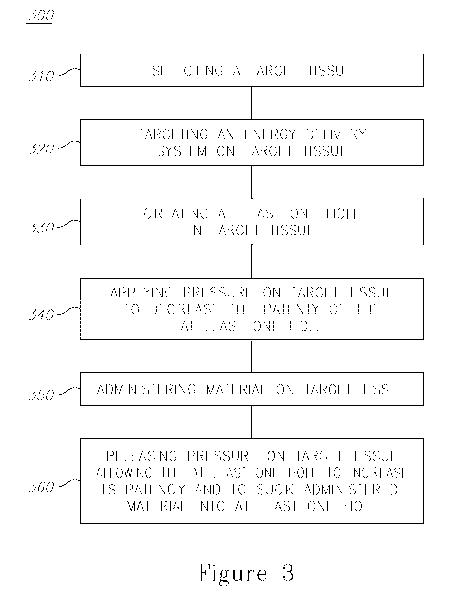
Referring now to figure 3, a high level flowchart describes one embodiment of
the present method. The method involves, at stage 310, selecting a target
tissue 60.
At stage 320, an energy delivery system 50 is selected for the target tissue
60. Stage
330 involves creating at least one hole 71 in the target tissue 60, whilst at
stage 340,
pressure is applied on the target tissue 60 to decrease the patency of the at
least one hole
71. A material 110 is administered on target tissue 60 at stage 350, and
finally at stage
360, the pressure on the target tissue 60 is released, allowing the at least
one hole 71 to
increase its patency and to suck the administered material 110 into the at
least one hole
71.
Referring now to figure 4 which illustrates target tissue 60 and an array of
holes
400 which are filled with fluid or material 410. The source of the fluid
inside the
holes may be internal or external. Interstitial fluid may diffuse into the
hole through the
hole wall as a result of the fractional treatment. In addition, fluid and
therapeutic
or cosmetic material may be administered onto the target tissue from the
material/fluid
reservoir. Administered material or fluid may be controlled by one or more
methods of the present invention so that it will fill the hole volume.
In this embodiment of the present invention, (figure 5), a transducer 450 is
in contact with the target tissue directly or through a coupling material. In
one
embodiment the coupling material is also administered from the material
reservoir 90
through the dispensing element 91. The transducer 450 is configured to deliver
ultrasound energy onto the target tissue and the fluid inside the holes 410 so
that micro
bubbles 420 are formed in the fluid 410. In one embodiment, the controller 30
is
configured to monitor the micro bubbles 420 formation, distribution, density,
size,
growth rate and shrinking rate and cavitation through at least one acoustical
sensor or at
least one optical sensor. The sensors are configured to detect signals which
are related
to at least one of the following: bubble formation, bubble distribution,
bubble density,
bubble size, bubble growing pace, bubble shrinking pace and bubble cavitation.
Sensors are coupled with their relevant energy sources to detect these related
signals.
12
CA 02851584 2014-04-09
WO 2013/076602
PCT/1B2012/056023
In one embodiment of the present invention, a light source probes the target
tissue and an optical sensor is configured to detect at least one of the
following
changes which are related to the target tissue or the fluid inside the hole:
changes in
light absorption characteristics; backscattered light intensity changes;
spectral changes;
or reflection changes. In yet another embodiment of the present invention an
ultrasonic transducer probes the target tissue and an ultrasonic sensor is
configured to
detect at least one of the following changes which are related to the target
tissue or the
fluid inside the hole: changes in reflected signals; changes in sound
velocity; and
changes in sound intensity. In yet another embodiment of the present invention
RF
electrodes are used to detect changes in the target tissue impedance or
electrical conductivity.
Monitoring the bubble's dynamic characteristics by sensors and a processing
unit serves as a feedback to the control unit 30 and transducer 450 is such a
way that
hole patency is controlled. The internal pressure inside the hole is increased
by an
increase in the average bubble size; bubble density or bubble distribution.
This
facilitates to overcome forces, such as pressure external to the hole, which
tend to
collapse the hole.
Figure 5 illustrates cavitation of bubbles in the fluid inside the hole,
according to an embodiment of the present invention. Cavitation energy (where
the bubbles implode or explode), facilitates further ablation and
fragmentation
of the hole from its internal volume and in a non- homogeneous way. As a
result, the cavitation increases both hole volume and its internal surface
area.
In yet another embodiment, when therapeutic or cosmetic material is
delivered into the hole, an increased hole volume and internal surface area of
the hole
may increase bioavailability of the active material; increase its diffusion
pace into the
target tissue and/or more intensely activate healing response of the tissue.
The ultrasound transducer 450 may be configured to deliver ultrasound waves
onto the tissue which are approximately perpendicular to the tissue surface,
according
to one embodiment of the present invention. In yet another embodiment,
transducer 450
may deliver surface waves to the tissue which propagate in the tissue
approximately parallel to the target tissue surface. In a further embodiment,
the
transducer 450 is located away from the target tissue and is configured to
delivers
13
CA 02851584 2014-04-09
WO 2013/076602
PCT/1B2012/056023
energy through surface waves. In yet a further embodiment, the transducer 450
delivers
ultrasound energy to cause the average bubble size to fluctuate so that the
hole patency
is pulsating. A pulsating hole patency increases fluid circulation inside and
outside
the hole and allows more efficient active material distribution and
absorbance. This is
highly desirable, particularly when therapeutic or cosmetic materials or
fluids are
dispensed onto the target tissue.
In another embodiment, an abrasive material is supplied into the hole from the
material reservoir. The abrasive material per-se interacts with the ultrasound
energy or
with light energy causing the abrasive material to absorb more energy and
explode
toward the hole wall and therefore increase the ablation rate and hole growth.
This
increases the internal surface area of the micro hole, enabling more fluid to
enter the
hole, which may prove an advantage during the use of therapeutic or cosmetic
fluids.
In the above description, an embodiment is an example or implementation of
the invention. The various appearances of "one embodiment", "an embodiment" or
"some embodiments" or "embodiments" do not necessarily all refer to the same
embodiments.
Although various features of the invention may be described in the context of
a single embodiment, the features may also be provided separately or in any
suitable
combination. Conversely, although the invention may be described herein in the
context of separate embodiments for clarity, the invention may also be
implemented
in a single embodiment.
Furthermore, it is to be understood that the invention can be carried out or
practiced in various ways and that the invention can be implemented in
embodiments
other than the ones outlined in the description above.
The invention is not limited to those diagrams or to the corresponding
descriptions. For example, flow need not move through each illustrated box or
state,
or in exactly the same order as illustrated and described.
Meanings of technical and scientific terms used herein are to be commonly
understood as by one of ordinary skill in the art to which the invention
belongs, unless
otherwise defined.
14
CA 02851584 2014-04-09
WO 2013/076602
PCT/1B2012/056023
While the invention has been described with respect to a limited number of
embodiments, these should not be construed as limitations on the scope of the
invention, but rather as exemplifications of some of the preferred
embodiments. Other
possible variations, modifications, and applications are also within the scope
of the
invention.