Note : Les descriptions sont présentées dans la langue officielle dans laquelle elles ont été soumises.
CA 02851682 2014-04-09
WO 2013/057306 PCT/EP2012/070848
APPARATUS FOR MONITORING ONE OR MORE PARAMETERS
OF THE EYE
FIELD OF THE INVENTION
This Invention relates to an apparatus for monitoring one or more parameters
of the eye.
BACKGROUND OF THE INVENTION
The invention refers to the field of ophthalmology, specifically refractive
eye diagnostic and
eye surgery. For most refractive eye treatments
(1) pre-surgery diagnostic information of the patient's eye is determined to
choose the
adequate procedure (e.g. implant vs. laser) and define the individual
treatment steps
(e.g. where to cut or how to align the implant),
(2) the individual surgery treatment is performed inserting refraction
correcting
implants (e.g. IOUs, corneal inlays) or executing surgery actions (e.g. cut
incisions,
apply laser shot patterns) and
(3) post-surgery diagnostic information of the patient's eye including implant
and/or
surgery action is determined.
(1) and (3) are typically performed outside the operation room using
diagnostic devices like
keratometer, topographer, wavefront analyzer, scheimflug devices,
interferometer or slit
lamps. (2) is typically performed in the operation room using a general
purpose surgical
microscope and adequate tools to support the surgeons manual work (e.g.
knifes, phaco
machine) or using dedicated devices for partial or full automation of surgical
steps (e.g.
refractive excimer laser treatment, cataract laser treatment).
Currently there is a wide range of diagnostic devices that measure properties
of the eye. A
topograph or keratometer determines the shape and curvature of the patient's
cornea (e.g.
Zeiss Atlas), a wavefront device determines the full refraction of the
patient's eye optics (e.g.
AMO Wavefront Sciences COAS), an interferometer measures the axial length of
the
patient's eye ball (e.g. Haag-Streit LenStar LS900), a scheimflug device
measures the front-
side and back-side of the corneal refraction as well as the thickness (e.g.
Oculus Pentacam)
and a slit lamp provides an image of the patient's front of the eye for manual
examination by
the doctor.
All different diagnostic approaches and associated devices evolved to accurate
tools with a
high repeatability for single eye measurements and therefore are applied pre-
surgery as well
as post-surgery for examination to verify clinical outcome.
There are further approaches appearing on the ophthalmology landscape for
intra-surgery
measurement of the eye. An intra-surgery keratometry hand tool (e.g.
astigmatic ruler by
STORZ) can be used to roughly measure the corneal shape and its changes during
the
surgery, an intra-surgery wavefront device - in principle ¨ allows the
determination of the
required power and astigmatism of an artificial lens after the removal of the
natural lens (e.g.
Wavetec ORange). All intra-surgery refraction measurement tools suffer from
the moment of
taking the measurement: The moment of eye surgery. Intra-surgery the eye
properties are
changed compared to the natural no-surgery condition. The intra ocular
pressure might be
1
SUBSTITUTE SHEET (RULE 26)
CA 02851682 2016-08-03
higher, the cornea might be deformed due to mechanical impacts, the refraction
of eye
fluids changed due to partial exchange of fluids, etc. But independent from
this general
drawback, the repeatability of those devices in one moment on one specific eye
is
reasonable.
All named devices and tools in this section above have in common the
availability of a
more or less consistent intra-device coordinate system ("device-consistent"
which
means that the tool or device provides from a patient X measured at one moment
T
multiple times a consistent output) but they all lack a full process covering
consistent
coordinate system ("process-consistent"). With a process-consistent coordinate
system every process step (measurement or treatment) where the patient's eye
is
visually acquired, can be matched and transformed to an initially defined
reference
coordinate system.
Due to the lack of a process-consistent coordinate system, systematic errors
that
occur between different steps are directly impacting the overall treatment
error. Some
examples:
a) Sit-to-Sit-Error: Current practice is making all diagnostic measurements
with
the patients head is in an upright position. The assumption of 99% of surgeons
is that the gravitation keeps the eye in the exact orientation for every
measurement. This way a combination of measurement results from different
devices can easily be performed. Unfortunately this assumption is wrong. The
eye can rotate up to 7 from one sitting position to another.
b) Marker-Error: Current practice is the use of ink markers or ink marker
tools for
marking axes or positions on the cornea or the limbus border. The accuracy for
using ink markers is limited due to the size of the marker (e.g. can be a 50
thick
mark), the unknown coordinate system while the surgeon is doing the marking
(see a)) as well as the accuracy of reading a marker. The errors can easily
sum
up to 6 or more.
c) Surgeons-Error: Till now e.g. the cataract surgeon is doing most surgery
steps
that require special accuracy fully manual: They position incisions or align
implants based on the marks they did previously. Besides the Marker Error the
mechanical precision of the surgeon fingers needs to be taken into account.
d) Implant-Error: Depending on the type of implant different post-surgery
movements of the implant are likely to occur. For example early toric IOL
2
CA 02851682 2016-08-03
designs tend to move post-operatively up to 100 based on slit lamp
assessment.
Deriving guidelines, nomograms or new implant designs and tool designs from
the
overall clinical outcome a separation of different systematic error influences
like a)-d)
could not be determined or distinguished.
With the high optical complexity of latest generation implants or latest
generation laser
systems this demand for more diagnostic and surgery accuracy is already
present, but
with existing tools only overall errors can be determined but no error
propagation
addressing every single diagnostic step or surgery step.
SUMMARY
Certain exemplary embodiments provide an apparatus for monitoring one or more
parameters of the eye of a patient over multiple sessions which are temporally
spaced
apart and between which the eye of the patient can have moved, said apparatus
comprising: a camera for taking one or more images of the eye; an illumination
unit for
illuminating the eye by a ring-shaped light pattern to generate corneal
reflections; a
module for determining during a first session the location of the corneal
reflections in
the image of the eye; a module for determining during said first session based
on said
determined location of the corneal reflections, at least one further parameter
of the eye
and its coordinates in a first coordinate system based on a geometrical model
representing the eye as a spherical eyeball having a spherically shaped cornea
mounted thereon; a module for determining during a second session temporally
spaced apart from said first session said location of said corneal reflections
of the eye
and based thereon said further eye parameter and its coordinates in a second
coordinate system; a module for determining the eye motion in six degrees of
freedom
between said first and said second session and for determining a coordinate
transformation based thereon; a module for transforming based on said
determined
eye motion said further eye parameter and its coordinates from said first
coordinate
system into said second coordinate system; a module for quantifying the change
of
said further eye parameter, visualizing the change, or a combination thereof,
between
said first and said second session based on said further parameter and its
coordinates
measured during said second session and said transformed parameter and its
coordinates measured during said first session.
2a
CA 02851682 2016-08-03
In view of the foregoing situation, according to one embodiment there is
provided a
process-consistent coordinate system every process step (measurement or
treatment)
where the patient's eye is visually acquired, can be matched and transformed
to an
initially defined reference coordinate system. This overcomes the
disadvantages of the
lack of a coherent process coordinate system over multiple sessions which may
comprise pre-surgery, surgery and post surgery.
2b
CA 02851682 2014-04-09
WO 2013/057306
PCT/EP2012/070848
According to one embodiment there is provided an apparatus for monitoring one
or more
parameters of the eye of a patient over multiple sessions which are temporally
spaced apart
and between which the eye of the patient can have moved, said apparatus
comprising:
a camera for taking one or more images of the eye;
an illumination unit for illuminating the eye by a ring-shaped light pattern
to generate corneal
reflections, said illumination unit being preferably located such that the
center of the ring is
coaxial with the optical axis of the camera;
a module for determining during a first session the location of the corneal
reflections in the
image of the eye;
a module for determining during said first session based on said determined
location of the
corneal reflections, at least one further parameter of the eye and its
coordinates in a first
coordinate system based on a geometrical model representing the eye as a
spherical eyeball
having a spherically shaped cornea mounted thereon;
a module for determining during a second session temporally spaced apart from
said first
session said location of said corneal reflections of the eye and based thereon
said further
eye parameter and its coordinates in a second coordinate system;
a module for determining the eye motion in six degrees of freedom between said
first and
said second session and for determining a coordinate transformation based
thereon;
a module for transforming based on said determined eye motion said further eye
parameter
and its coordinates from said first coordinate system into said second
coordinate system;
a module for quantifying and/or visualizing the change of said further eye
parameter between
said first and said second session based on said further parameter and its
coordinates
measured during said second session and said transformed parameter and its
coordinates
measured during said first session.
Such an arrangement allows to monitor eye parameters which are determined
based on the
corneal reflections even over multiple sessions which are temporally spaced
apart.
According to one embodiment said at least one further parameter is determined
based on an
eye model which represents the shape and location of the eye by a spherical
eyeball and a
cornea mounted thereon and having a spherical shape or the shape of an
ellipsoid to thereby
enable the calculation of said at least one further parameter using the
measured location of
said corneal reflections and said the eye model.
This enables the determination of eye parameters which are not directly
measurable but
which can be determined using the aye model and which can then be monitored
over time.
According to one embodiment said at least one further eye parameter comprises
one or
more of the following:
a) the k-readings which define the shape of the cornea in terms of rotation
ellipsoid
parameters;
b) the line of sight as the line connecting the pupil center and a fixation
point of
known location;
c) the corneal chamber depth;
d) the visual axis of the eye;
3
SUBSTITUTE SHEET (RULE 26)
CA 02851682 2014-04-09
WO 2013/057306
PCT/EP2012/070848
e) the determination whether the eye is the left eye or the right eye.
These are examples of further eye parameters which are of interest to be
monitored even
over sessions which are temporally spaced apart and between which a movement
of the eye
has occurred which is then compensated by the proposed approach.
According to one embodiment said module for quantifying and/or displaying the
change of
said further eye parameter comprises:
A module for displaying said further parameter measured during said second
session and
said transformed parameter measured during said first session in the image of
the eye taken
during said second session; and/or
a module for calculating the difference between said further parameter
measured during said
second session and said transformed parameter measured during said first
session and for
visualizing said difference in said image of the eye taken during said second
session.
This enables the comparison of the development of an eye parameter over time,
e.g. by
comparing a post-surgical change with the situation during surgery, or by
comparing two
different post-surgical instances in time while the eye movement between the
two
measurements is compensated. The eye parameter as determined at the two
instances of
time may be directly visualized by displaying it in the image with the eye
motion being
compensated, or there may be calculated a difference (like a difference in x-,
y- or rotation
parameters) and just the difference being displayed in the image.
According to one embodiment said at least one further eye parameter comprises
the k-
readings which are measured by determining a best fit ellipse to the corneal
reflections and
determining the major axis, the minor axis and the orientation of the ellipse.
This enables the determination of astigmatism including the length of the
steep and flat axis
of the cornea as well as the orientation of the astigmatism. The diameter of
the best fit
cornea sphere can be approximated by the mean of flat and steep axis..
According to one embodiment said apparatus further comprises a fixation target
at known
coordinates, preferably on the optical axis of the camera, and said at least
one further eye
parameter comprises the visual axis which is determined as the vector
connecting the
cornea center and the known fixation target, where the cornea center is
determined based on
the location of the corneal reflections.
This enables the determination of the visual axis.
According to one embodiment said at least one further eye parameter comprises
the angle
kappa between the visual axis and the pupil axis, or
said further parameter is the intersection point between the visual axis and
the cornea
surface, where the cornea radius is determined based on the location of said
corneal
reflections.
4
SUBSTITUTE SHEET (RULE 26)
CA 02851682 2014-04-09
WO 2013/057306 PCT/EP2012/070848
This allows the determination of further parameters which are interesting for
the surgeon.
According to one embodiment said at least one further eye parameter comprises
the anterior
chamber depth which is determined based on determining the radius of the
limbus RI and
assuming it to be a circle of latitude on the best fit cornea sphere with
radius Rc which is
determined based on the corneal light reflections such that the corneal
chamber depth CD is
derived by
CD = Rc - sqrt(RcA2 ¨ RIA2).
The anterior chamber depth is an interesting information for the surgeon,
According to one embodiment said at least one further eye parameter comprises
the line of
sight which is determined as the vector connecting the pupil center and said
fixation point of
known location, with the z-coordinate of the pupil center being determined
based on a known
distance between camera and the eye and the x- and y-coordinates of the pupil
being
determined based on measuring the pupil location in the image, and/or.
said at least one further eye parameter comprises the pupillary axis being the
line going
through the center of the pupil and being orthogonal to the cornea surface.
Line of sight and pupillary axis may be determined in this way.
According to one embodiment said at least one further eye parameter comprises
the
determination of whether the center of the limbus or the center of the cornea
is closer to the
optical axis of the camera when the patient fixates a known fixation point
lying on the optical
axis of the camera.
This enables the determination whether the eye is the left eye or the right
eye. It may be
used as a safeguard mechanism to prevent the surgery or diagnosis being
performed on the
wrong eye.
According to one embodiment said first session is a pre-surgery session and
said second
session is an intra surgery session or a post surgery session, or
said first session is an intra-surgery session and said second session is a
post surgery
session, or
said first session is a post-surgery session and said second session is
another post surgery
session performed at a later time.
These are suitable examples of sessions at different instances of time for
which the eye
parameters may be compared while compensating for the eye motion between the
sessions.
According to one embodiment the apparatus further comprises:
5
SUBSTITUTE SHEET (RULE 26)
CA 02851682 2014-04-09
WO 2013/057306 PCT/EP2012/070848
A module for measuring and recording said at least one further eye parameter
during
multiple sessions over time in order to record the change of said at least one
further eye
parameter over time.
This enables the recording and monitoring of the development of further eye
parameters and
thereby of the surgical result or impact over an arbitrarily long time period
in a consistent
coordinate system by compensating the eye motion. In this way e.g. studies
regarding the
long term success or failure of surgical techniques may be carried out which
so far are not
possible.
According to one embodiment said at least one further parameter comprises a
surgical or
implant related parameter which comprises one or more of the following:
the position and/or orientation of an implant in the eye, and/or
the location and/or contour of corneal or limbal or sclera! incisions
the location and/or contour of the rhexis;
and/or the overlap between the rhexis and the implanted lens.
Such an arrangement allows to monitor surgical parameters even after the
surgery has been
performed to check whether there has been any temporal change of the surgical
parameters
like implant-related eye parameters or the location or contour of incisions.
This is an
important diagnostic information for monitoring the success or failure of
surgery during the
post-surgical phase.
According to one embodiment the apparatus further comprises:
A module for visualizing an arbitrary combination of said at least one or more
further eye
parameters determined during said first session and a possibly different
arbitrary
combination of said at least one or more further eye parameters determined
during said
second session in the same image such that the eye motion between said first
and second
session is compensated.
This allows the visualization of any surgical or other parameters in any
combination which
are of interest while compensating for the eye motion between different
sessions.
DESCRIPTION OF THE DRAWINGS
Figures 1 to 15 illustrate embodiments of the invention.
DETAILED DESCRIPTION
According to one embodiment there is provided an apparatus which enables a
solution for
monitoring eye properties related to eye surgery over time, between any two of
the following:
= pre surgery
6
SUBSTITUTE SHEET (RULE 26)
CA 02851682 2014-04-09
WO 2013/057306
PCT/EP2012/070848
= intra surgery
= post surgery
In the following there will be referred to spatial and refractive eye
properties as "eye
parameters".
For intra surgery measurements the solution according to one embodiment
requires a
microscope camera that is connected to a PC.
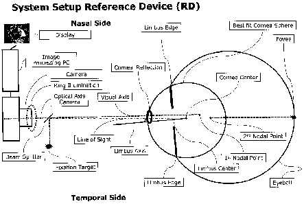
For pre and post surgery measurements according to one embodiment the solution
described here uses a specific apparatus hereinafter called a 'Reference
Device' (RD) which
consists of a PC connected to a digital camera and an illumination system on a
cross table
which allows capturing a high resolution color image of a patients eye in a
defined position.
The apparatus according to one embodiment and its use in connection with an
eye is
schematically illustrated in Fig. 1.
The illumination system of the RD generates a ring-shaped illumination pattern
and may e.g.
consist of a concentric ring of LEDs around the optical axis of the camera and
a fixation LED
which is injected on the optical axis of the camera. Preferably the ring of
LEDs is coaxial with
the optical axis of the camera and the optical axis of the camera is
orthogonal to the area of
the ring.
The acquired images are processed on the PC and can be used to automatically
or manually
measure either absolute eye parameters as they are at the time of image
acquisition or
changes of eye parameters relative to a reference image of a previous
measurement
session.
According to one embodiment the apparatus allows determining the spatial
relation of the
measured parameters with respect to each other within and between measurement
sessions
by actively measuring how the eye did move in 6 degrees of freedom between 2
measurement sessions.
The eye motion in 6 degrees of freedom is according to one embodiment measured
based
on registration of scleral blood vessel features or limbus, iris features and
corneal reflections
of a defined illumination system between 2 sessions.
One initial (usually pre surgery, but post-surgery is also possible) reference
measurement
serves as a reference coordinate system for all subsequent measurement
sessions (pre or
post surgery) of the same eye.
All parameters measured in subsequent sessions can be transformed into the
reference (or
vice versa) coordinate system by applying a spatial similarity transformation
that accounts for
the eye motion between the current measurement and the reference measurement.
Once
transformed to the reference coordinate system the parameters from different
measurements
, can be compared and the influence of eye motion is eliminated.
This approach is used in one embodiment for analyzing parameters like the
position and the
orientation of eye implants (e.g. 10Ls) in the eye. This way it can be
monitored how stable
the implant is located and oriented in the eye over time without being limited
in accuracy to
the amount of eye motion between measurement sessions.
Typical eye parameters that may be measured with the RD in a pre surgery
reference
measurement session are:
1) Pupil position, shape and size (photopic, scotopic, mesopic)
2) Limbus position shape and size
3) K-readings
7
SUBSTITUTE SHEET (RULE 26)
CA 02851682 2014-04-09
WO 2013/057306
PCT/EP2012/070848
4) Line of sight (LOS)
5) Approximation of corneal chamber depth
6) Intersection of LOS with cornea surface and angle kappa
7) OD/OS classification
These eye parameters may be measured in a pre-surgery session and then later
in intra-
surgery or a post-surgery session, and their change or development over time
may then be
determined and visualized.
The eye motion which then enables the transformation of the eye parameters
from one
session to another according to one embodiment is determined by measuring the
following:
8) Relative eye motion with respect to the reference measurement by measuring
a) Relative translations in X and Y
b) Relative translation in Z
c) Relative cyclotorsion (around Z axis)
d) Relative roll and tilt (around X and Y axis)
Other parameters which relate to ophthalmic surgery and the placement of
implants may be
measured as well.
In a (subsequent) intra or post surgery measurement session the following eye
parameters
may be measured in addition to (or instead of) the aforementioned eye
parameters:
9) Orientation and Position of implants in the eye
a) Location of the implant markings in the eye (toric marks or multifocal
rings)
b) Rotational orientation of implants
c) Roll and Tilt of implants
d) Implant contour
e) XY-Position of the implant center
f) Location of the implant haptics in the eye
Moreover, another type of parameters which is also related to implants may be
measured,
namely
10) The Rhexis in the capsular bag, specifically
a) Contour
b) Diameter
c) XY Position in the eye.
d) Overlap with lens
In an alternative instance the RD contains an additional Scheimpflug or
interferometer setup
that allows to measure inside the cornea and
lens tissue.
In such a setup in addition to the parameters mentioned above, corneal
incisions can be
8
SUBSTITUTE SHEET (RULE 26)
CA 02851682 2014-04-09
WO 2013/057306
PCT/EP2012/070848
measured in terms of location in the eye, width and depth as well as the
distance of the
implant to the cornea.
In a second alternative instance the RD also contains a placido ring
illumination that allows to
analyze the topography of the cornea. In such a setup the exact changes in
corneal
topography e.g. before and after LASIK laser treatment can be assessed. By
applying the
spatial similarity transformation to the topography data it is possible to
ensure that the
topography data is correctly aligned and changes in the topography of the
cornea are being
calculated correctly.
In a third alternative instance the RD also contains a wavefront analyzer
(Hartmann-Shack-
Sensor) that allows to analyze the full refraction of the eye.
In yet another alternative instance a registration of the image from the RD is
performed to
other dedicated eye diagnosis devices allowing to transform the dedicated
parameters
measured by these devices to the reference coordinate system provided by the
RD.
In this instance changes in these additional spatial eye parameters can also
be monitored
over time in the consistent reference coordinate system provided by the RD.
In the following embodiments of an apparatus according to the invention (a
reference device)
will be described and its operation and function will be explained.
The main functionality of the apparatus according to one embodiment is to:
= measure multiple eye parameters or parameter sets in different
measurement
sessions.
= determine the eye motion between the measurement sessions.
= apply a spatial similarity transformation to transform each eye parameter
or
parameter set to the reference coordinate system defined by the initial
reference
measurement.
= quantify and display changes in eye parameters or eye parameter sets
between
measurement sessions pre-, intra- and post-surgery.
= quantify and display differences between surgery plan and post surgery
outcome.
The eye parameters in one embodiment are measured by combining image
processing with
a generic eye model. For example, according to one embodiment the model
represents the
eyeball as a sphere with the cornea being also spherical (or in one embodiment
having an
ellipsoid shape) being mounted thereon. Using such an eye model allows to
'indirectly
measure properties like the corneal chamber depth which is not directly
visible in the image.
Now it will be explained how according to embodiments eye parameters are
determined
which may then be transformed from one session to the other using the detected
eye motion
1) Pupil position, shape and size (photopic, scotopic, mesopic)
Pupil detection is a classic image processing task. A classic threshold based
approach is
used here. By varying the illumination intensity the pupil of the patient can
be brought into
a photopic, scotopic and mesopic condition (pupil size changes).
9
SUBSTITUTE SHEET (RULE 26)
CA 02851682 2014-04-09
WO 2013/057306
PCT/EP2012/070848
2) Limbus position shape and size
Similar as for pupil detection a standard approach using limbal edge detection
and a
circular fit is used here.
3) K-readings:
The k-readings define the shape of the cornea in terms of rotation ellipsoid
parameters as
minor axis (steep axis in ophthalmology) major axis (flat axis in
ophthalmology) and axis
orientation. Also here in one embodiment a well known keratometry approach is
being
applied by detecting the corneal reflections of the coaxial ring of LEDs of
the RD. The
best fit ellipse into these reflections gives the parameters of the k-
readings.
4) Line of sight (LOS)
The Line of sight connects the fixation point with the center of the eye's
entrance pupil.
The RD takes an image from a defined distance Zp to the eye. By design the
imaging
geometry of the camera is known as well as the position of the fixation target
with respect
to the projection center of the camera. The pupil can therefore be measured in
3
dimensions with its coordinates Xp ,Yp and Zp. The 3d vector connecting the
entrance
pupil and the fixation target gives the LOS. This is schematically illustrated
in Fig. 2.
5) Approximation of corneal chamber depth
The radius Rc of the best fit sphere resembling the cornea surface is the mean
of flat and
steep axis as determined from the
k-readings.
Assuming the limbus with radius RI to be a circle of latitude on the best fit
cornea sphere
with radius Rc, an approximation of the corneal chamber depth CD can be
derived by
CD = Rc - sgrt(RcA2 ¨ RIA2). This is schematically illustrated in Fig. 3.
6) Intersection of LOS or visual axis with cornea surface
The intersection is a valid reference point for implanting corneal inlays and
for centering
laser treatments. It can be approximated by intersecting the best fit cornea
sphere with
the LOS.
The lateral coordinates of the center of this sphere Xc and Yc are well
approximated by
the center of the corneal reflections of the ring of LEDs. The Z coordinate of
the sphere
center is modeled by Zc = Zp ¨ CD + Rc.
Using simple vector algebra the intersection between the LOS and the sphere
defined by
its center [Xc,Yc,Zel and its radius Re can be calculated.
Implicitly this intersection is also a representation for the often cited
angle kappa or
lambda. In the literature angle kappa is referred to as the angle between the
Visual Axis
(VA see definition in section below) and the Pupillary axis (PA) connecting
the pupil
center [Xp,Yp,Zp] to the cornea center [Xc,Yc,Zc].The PA is therefore a normal
to the
cornea surface. This and its determination is illustrated in Fig. 4. The
determination of the
PA may in one embodiment the carried out as follows:
1. Detect Pupil center in image to get pupil XY
2. Detect corneal reflections
3. Calculate cornea center XYZ and Cornea radius from CRs
4. Detect Limbus size in image
SUBSTITUTE SHEET (RULE 26)
CA 02851682 2014-04-09
WO 2013/057306 PCT/EP2012/070848
5. Use limbus size and cornea radius to calculate anterior chamber depth
6. Use anterior chamber depth and cornea center XYZ to calculate pupil Z
7. PA is vector through pupil XYZ and cornea center XYZ
Since an objective measurement of the VA is not trivial often the LOS is used
instead, its
determination has already been described above. The angle between PA and LOS
is
referred to as angle lambda in the literature (see Fig. 5). In practical terms
lambda =
kappa (up to 0.2 ).
However, according to one embodiment the actual visual axis may be determined.
For
that purpose it is in one embodiment assumed that the cornea center matches
with the
first nodal point. Then the visual axis can be determined as the line
connecting the
fixation point and the center of the cornea. This is illustrated in Fig. 6.
Fig. 7 then
illustrates the determination of the angle kappa. The determination in one
embodiment
may be carried out using the following steps:
1. Detect corneal reflections
2. Calculate cornea center XYZ and Cornea radius from CRs
3. Use model assumption cornea center = 1st nodal point
4. Use given XYZ coordinates of fixation target
5. VA is vector through 1st nodal point XYZ and fixation target XYZ
7) OD/OS
classification:
Another parameter that can be derived from images acquired with the RD is
whether the
current image shows a left or a right eye. This parameter is rather
interesting for usability
purposes and gross error
prevention.
It is well known in the literature that the Visual Axis (VA) (ray of light
that connects the
fixation point with the fovea through the first and second nodal point of the
eye) has an
inclination towards the nasal side compared to the Optical Axis of the Eye
(OAE) (see
image below). The angle between the OAE and the VA is referred to as angle
ALPHA in
the literature and has a magnitude of about
50.
The OAE is the best fit line through the centers of curvature of the best fit
spheres to the
refractive surfaces of the eye. The refractive surfaces are the front and back
surface of
the cornea and the front and back surface of the lens.
By centering the patient's eye in the camera image and by asking the patient
to fixate on
the target, the patient roughly aligns the VA to the Optical Axis of the
Camera (OAC).
Hence the OAE has an angle of about 5 to the OAC.
The center of the corneal reflection(s) resembles a very good approximation of
the image
position of the cornea center which by definition of the OAE lies on, or very
close to the
OAE.
A new aspect utilized in this embodiment is that an axis connecting the limbus
center and
the cornea center, which will be referred to as Limbus Axis (LA), also
provides a very
reliable and stable reference to quantify the inclination of the VA towards
the nasal side.
The OD/ OS classification based on the cornea center and the limbus center is
reliable
since:
= The patient is fixating and aligns the VA to the OAC.
= Both, the center of the cornea and the center of the limbus do lie on the
LA and very
close to the OAE.
= The limbus center is always closer to the camera than the cornea center.
= The VA points to the nasal side.
11
SUBSTITUTE SHEET (RULE 26)
CA 02851682 2014-04-09
WO 2013/057306
PCT/EP2012/070848
This is illustrated in Fig. 8.
It follows that in the camera image the cornea center appears left of the
limbus center for
the left eye and right of the limbus center for the right eye. This is
illustrated in Fig. 9.
In the following there will be explained in somewhat more detail how according
to one
embodiment the eye motion is measured and the coordinated transformation is
determined.
According to one embodiment there is determined the relative eye motion with
respect to the
reference measurement in 6 degrees of
freedom.
This is the basis for the link between measurements taken during different
measurement
sessions that may be minutes, days, months or years apart and may be performed
on
different diagnostic devices. US 7,600,873 B2 teaches how to utilize eye
features like sclera
blood vessels, pupil, limbus, iris features and/or corneal reflections for
recovering eye motion
in 6 degrees of freedom.
The 6 recovered parameters (translations in X,Y, Z and rotations around X,Y
and Z-axes)
describe a transformation ¨ a spatial similarity transformation - that may be
applied to any
derived coordinates on the eye or in the eye. In one embodiment the same
feature based
approach as described in US 7,600,873 B2 is used.
In the foregoing there have been described embodiments where eye parameters
which relate
to the shape or location of the eye or its optical properties are determined
by using an image
of the eye and of corneal reflections of a ring shaped illumination source and
eye model
which represents the eye itself by a geometrical model. In addition to the
corneal reflections
which are directly determined, one or more of such "further eye parameters are
determined
using the eye model: the determined setting of the camera, the illumination
source, and in
some embodiments also comprises a known fixation point. These parameters are
determined over multiple sessions to monitor and record the change of these
parameters
over time between different sessions by using a coordinate transformation
which is based on
the determination of the eye movement in six dimensions. It should be noted
that the
described "further parameters of the eye" may be measured alone or in an
arbitrary
combination in a measurement session.
Now embodiments will be described in which further surgical eye parameters,
e.g. eye
parameters which relate to implants are determined, such as e.g. the
orientation and/or
position of implants. These parameters may be measured in addition to the
"further eye
parameters" described before, or they may be measured alone or alternatively
to them during
one session. Like with the "further eye parameters" described before these
implant related
parameters are measured during multiple sessions which are temporally spaced
and
between which the patient ¨ and the eye ¨ typically has moved. Also for these
"implant-
related parameters" the movement of the eye between different sessions in six
degrees of
freedom is determined to obtain a transformation which enables the
transformation of the
measured parameters into a consistent coordinate system which is consistent
over the
multiple sessions. This enables then to compare and monitor how these implant
related
parameters change over time which is very important information for the
doctor. For that
purpose these parameters may be compared with their corresponding implant-
related
12
SUBSTITUTE SHEET (RULE 26)
CA 02851682 2014-04-09
WO 2013/057306
PCT/EP2012/070848
parameters as determined in previous sessions, or with the "further" non-
implant related
parameters. The parameters of different sessions (non-implant related ones,
implant related
ones or any combination of both of them) which are to be compared may be
visualized within
the same image by using the coordinate transformation obtained by the eye
movement
determination which enables the doctor to judge the development of these
parameters over
time in a consistent coordinate system which compensates or eliminates the
effect of the
movement of the eye between different sessions.
Other surgical eye parameters which may be determined are e.g. the location
and/or contour
of corneal or timbal or scleral incisions. These parameters may have a
relation with an
implant (and may therefore in some embodiments be "implant-related
parameters"),
however, there are also surgical techniques like e.g. the LRI (limbus
relaxation incision)
where incisions are made without an implant being placed. For such surgical
techniques the
relevant parameters like the location and/or contour of corneal or timbal or
scleral incisions
may be determined over multiple sessions.
In the following embodiments will be described where implant-related eye
parameters are
determined. The implant related eye parameters may in one embodiment belong to
one of
two categories, the first one being the position and/or orientation of an
implant in the eye,
and the second one being related to the position and/or orientation of the
rhexis.
Both may also be combined, for example the position of the rhexis and the
location or shape
of a lens implant.
In the following some embodiments will be described in more detail.
First some embodiments measuring the orientation and/or position of implants
in the eye will
be described.
a) Location of the implant markings in the eye (toric marks or multifocal
marks)
Different eye implants like toric 10Ls or Multifocal 10Ls do have distinct
markers.
According to one embodiment these markers are automatically detected using
image
processing techniques, e.g. edge detection and/or template based feature
detection.
This way basically any man made feature on or in an inlay or implant can be
detected
and their lateral position in the eye can be monitored over time.
In the case of toric 10Ls e.g. the markings do show either the steep or the
flat axis of
the toric lens and they are used by the surgeon to accurately align the lens
in the eye.
In case of multifocal 10Ls, concentric rings in the lens are visible which are
used by
the surgeon to laterally position the lens. Fig. 10 illustrates these markings
and their
determination in an eye image.
b) Cyclotorsion orientation of implants
As mentioned above the cyclotorsional orientation of a toric IOL can be
recovered by
detecting the toric marks on the lens that resemble either the flat, the steep
or
implantation axis of the IOL (depending on the type). This is also illustrated
in Fig. 10
13
SUBSTITUTE SHEET (RULE 26)
CA 02851682 2014-04-09
WO 2013/057306 PCT/EP2012/070848
by the axis that is overlaid over the steep or the flat axis of the toric lens
and which
have been determined based on the location of these markings.
c) Roll and Tilt orientation of implants
The exact shape and refraction of the implant (for example an 10L) is known.
This
allows for a model based ray tracing approach to recover roll, tilt
orientation and
lateral position of the IOL in the eye, which is used according to one
embodiment to
determine the roll and tilt of an implant.
The known coaxial illumination system of the RD creates reflections on the
front side
and backside of the IOL ( 3rd and 4th order purkinje images), as illustrated
in Fig. 11.
If the lens rolls or tilts, the 3rd and 4th order purkinjes will move with
respect to each
other. In the special case in which the 31d and 4th order purkinje
superimpose, the
optical axis of the IOL is aligned with the optical axis of the camera. The
locations of
the 3rd and 4th order purkinje images can be used to determine the roll and
tilt of the
implant, e.g. by using an approach as described in "Reproducibility of
intraocular
lens decentration and tilt measurement using a clinical Purkinje meter",
Yutaro Nishi et. al. J Cataract Refract Surg 2010; 36:1529-1535 Q 2010 ASCRS
and ESCRS. Reference is in this context also made to Fig. 12 which illustrates
the
determination of the determination of the orientation of the intraocular lens
based on
the 3rd and 4th order purkinje reflections. Like in the usage of the reference
device
before a circular illumination is applied which is coaxial with the camera
axis. The
orientation determination method in one embodiment then may comprise the
following steps:
1. Detect center of purkinje 3rd
2.Detect center of purkinje 4th
3.Use the IOL shape information including distance between anterior and
posterior
centers of curvature = DCC
4. Recover optical axis of lens using distance between 3rd and 4th purkinje
centers,
camera parameters and DCC.
d) Implant contour
The implant contour is clearly visible in the RD images if it is not
obstructed by iris
tissue. The unobstructed parts can be recovered with standard image processing
techniques like edge detection. By fitting a known edge shape model of the
inlay in
the detected contour parts or detected implant markings in one embodiment it
is also
possible to recover the obstructed parts of the inlay contour. This is
illustrated in Fig.
13.
e) XY-Position of the implant center
Since the shape of the implant is known a variety of techniques can be used to
recover the lateral position of the implant center. According to one
embodiment,
detecting the location of the implant marks, using the implant contour to
recover the
center or the ray tracing approach described under c) can be used.
f) Location of the implant haptics in the eye
For detecting the haptics according to one embodiment the same approach as for
the
implant contour is employed. The haptics have a well defined shape and are
basically
part of the implant contour.
14
SUBSTITUTE SHEET (RULE 26)
CA 02851682 2014-04-09
WO 2013/057306
PCT/EP2012/070848
Now some embodiments where the implant related parameter relates to the rhexis
will be
described.
g) Contour
Using edge detection techniques can recover the clearly visible rhexis in the
RD
images. Alternatively it can also be measured by manually selecting a polygon
that
best resembles the contour of the rhexis. The rhexis contour is illustrated in
Fig. 14.
h) Diameter
The diameter can be retrieved by least squares fitting of a circle or ellipse
into the
contour of the rhexis.
i) XY Position in the eye.
The XY position of the rhexis according to one embodiment can be defined and
determined as the center of the best fit circle or ellipse into the contour of
the rhexis.
j) Overlap with lens
Superimposing the contour of the rhexis with the contour of the lens. The area
inside
the contour of the lens implant and outside the contour of the rhexis is the
overlap.
This is illustrated in Fig. 15. This is an important measure to determine how
stable the
lens implant is in the eye. If the overlap on one side becomes too small
chances are
the implant will be instable.
In the foregoing several embodiments of the invention have been described
which come
along with several advantages.
E.g. by being able to spatially transform all measurements to an initial
reference frame (or
any arbitrary reference frame chosen in one of the sessions), any influence
due to a potential
eye motion can be eliminated and all measured parameters can be normalized
with respect
to the reference frame.
This allows a continuous monitoring of all measured eye parameters. A truly
measurement
driven approach to investigate the post surgery behavior of implants and
surgical cuts in the
eye becomes possible without being limited in accuracy to the amount of eye
motion
inherently present in all multi session diagnostic data collection trials.
The skilled person will recognize that the modules or units of the embodiments
of the
invention described before may be implemented by software or hardware or a
combination
thereof. In particular, the hardware may comprise a camera and a computer
which is
programmed to perform the tasks as described in connection with the
embodiments of the
invention, in particular such tasks as image processing to determine eye
parameters or
displaying for displaying eye parameters in addition to the eye image.
SUBSTITUTE SHEET (RULE 26)