Note : Les descriptions sont présentées dans la langue officielle dans laquelle elles ont été soumises.
CA 02851811 2014-04-10
DESCRI PTION
APPARATUS FOR CONTROLLING IN-VEHICLE HEATER
TECHNICAL FIELD
[0001] The
present invention relates to an apparatus for controlling an in-vehicle
heater that heats a heating medium for heating.
BACKGROUND ART
[0002] Electric vehicles and hybrid vehicles are provided with a hot-water
heating
device for heating the passenger compartment. Specifically, they are provided
with
a water circulation passage, at one position of which water is heated to be
hot water
by a heater (water-heating heater) and at another position (downstream side)
of
which heat exchange is performed by a heat exchanger between the hot water and
air blown to the passenger compartment, to thereby obtain hot air for heating
the
passenger compartment.
[0003] The power supply of such a heater is a high-voltage power supply, and
thus,
the heater is used at high voltage and high current. Therefore, there is a
possibility
that abnormal overheating is generated in the heater for some reason, and
thus,
overheating protection is required.
[0004] In Patent
Document 1, the temperature of a heater (including the
temperature of hot water obtained by the heater) is measured, and if the
temperature of the heater exceeds a predetermined value, forcibly turn off a
switch
for ON and OFF of the voltage supplying to the heater and maintain such an OFF-
state.
[0005] In Patent
Document 2, a temperature fuse is disposed in the heater
energizing circuit so as to be in series with the heater, and the temperature
fuse is
- 1 -
CA 02851811 2014-04-10
melted when the heater is abnormally overheated. When high power is applied
thereto, the temperature fuse does not have sufficient reliability, and thus,
multiple
heaters are connected in parallel, and the temperature fuse is provided for
each
heater so as to operate the temperature fuses at low power (low current).
CITATION LIST
PATENT DOCUMENTS
[0006] [Patent Document 1] Japanese Patent No. 3369881
[Patent Document 2] Japanese Laid-open (Kokai) Patent Application
Publication No. 2002-324653
SUMMARY OF THE INVENTION
PROBLEMS TO BE SOLVED BY THE INVENTION
[0007] In the technique disclosed in Patent Document 1, an occurrence of
abnormal overheating is determined by measuring the temperature of the heater
(including the temperature of hot water obtained by the heater). In the case
of
controlling energization of the heater using a switching device such as an
IGBT,
such a switching device may be abnormally overheated prior to the detection of
abnormal overheat of the heater, and thus, countermeasure for this is further
required.
In the case of detecting abnormal overheating of the heater and controlling
the heater to forcibly turn-off by a microprocessor, if control of the
microprocessor is
lost for some reason, no means is available for turning off the heater.
[0008] In the technique disclosed in Patent Document 2, a temperature fuse
operates under a low-power (low current) condition, and thus, it is necessary
to
choose a heater with a low-power density and a heater with a high-power
density
cannot be used. This causes a disadvantage when upscaling the heater, and
- 2 -
CA 02851811 2014-04-10
accordingly upscaling of a casing to accommodate the heater.
[0009] In view of the abovementioned problems, it is an object of the present
invention to provide an apparatus for controlling an in-vehicle heater to
further deal
with overheating protection when the microprocessor malfunctions.
MEANS FOR SOLVING THE PROBLEMS
[0010] An apparatus for controlling an in-vehicle heater according to the
present
invention includes, as a prerequisite, a heater that generates heat by
energization to
heat a heating medium for heating; a switching device that is disposed in an
energization circuit for the heater to be in series with the heater, the
switching device
being capable of turning energization ON and OFF; a driver that drives ON and
OFF the switching device; and a microprocessor that generates an instruction
signal
to the driver in response to a heating request.
[0011] Then, the apparatus for controlling in-vehicle heater further includes:
a first
temperature sensor that measures temperature of the switching device; and a
comparator that receives a signal from the first temperature sensor and
transmits a
signal when temperature of the switching devices is equal to or greater than a
predetermined temperature, and the device for controlling an in-vehicle heater
is
configured so that the switching device is forcibly turned OFF via the driver
in
response to the signal from the comparator.
EFFECT OF THE INVENTION
[0012] The present invention is configured to measure temperature of the
switching device, and in a case in which the switching device is overheated,
the
switching device is forcibly turned off to protect a switching device
requiring more
stringent protection, which can be protected preferentially (immediately).
Needless
to say, overheat protection for the switching device is performed, and at the
same
- 3 -
CA 02851811 2015-08-28
95839-8
time, overheat protection for the heater can be performed.
[0013] Since the comparator is provided as a separate circuit
configuration from
the microprocessor, even when control of the microprocessor is lost for some
reason,
overheating protection is enabled.
[0013a] In an aspect, there is provided an apparatus for controlling in-
vehicle heater,
which includes: a heater that generates heat by energization to heat a heating
medium for heating; a switching device that is disposed in an energization
circuit for
the heater to be in series with the heater, the switching device being capable
of
turning energization ON and OFF; a driver that drives ON and OFF the switching
device; and a microprocessor that generates an instruction signal to the
driver in
response to a heating request, the apparatus for controlling in-vehicle
heater,
comprising: a first temperature sensor that measures the temperature of the
switching
device; and a comparator that receives a signal from the first temperature
sensor and
transmits a signal when temperature of the switching devices is equal to or
greater
than a predetermined temperature, wherein the switching device is forcibly
turned
OFF via the driver in response to the signal from the comparator, wherein the
two
switching devices are provided in series with the heater on a power-supply
side and
on a ground side of the heater, wherein the single first temperature sensor is
provided
at a position at which temperature of the two switching devices can be
measured, and
wherein the single comparator is provided so as to correspond to the single
first
temperature sensor.
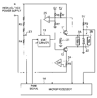
BRIEF DESCRIPTION OF THE DRAWINGS
[0014] Fig. 1 is a conceptual view of an in-vehicle heater including a
water-heating
heater according to one embodiment of the present invention.
- 4 -
CA 02851811 2015-08-28
95839-8
Fig. 2 is a circuit configuration view of an apparatus for controlling a water-
heating heater according to one embodiment of the present invention.
Fig. 3 is a view illustrating a specific example of a forcibly stopping port
part
of an IGBT driver.
MODE FOR CARRYING OUT THE INVENTION
[0015] Hereinbelow, embodiments of the present invention will be
described in
detail.
An in-vehicle heater according to the present invention is configured to
generate heat by energization to heat a heating medium for heating. As the
heat
medium, water (including water mixed with antifreeze or the like) is typically
used. In
the following embodiments, water is used as a heating medium.
[0016] Fig. 1 is a conceptual view of an in-vehicle heater including a
water-heating
heater according to one embodiment of the present invention.
A circulation passage 1 of water as a heating medium is provided, and
water is circulated by a pump 2.
[0017] At one position of the circulation passage 1, a heater (water-
heating heater)
3 is provided. The heater 3 heats water flowing through the circulation
passage 1,
thus yielding hot water. The heater 3 of the present embodiment includes two
- 4a -
CA 02851811 2014-04-10
=
heaters 3A and 3B electrically connected in parallel.
[0018] At another position (downstream side of the heater 3) of the
circulation
passage 1, a heat exchanger 4 is provided. The heat exchanger 4 is disposed in
an
airflow duct 5 from which conditioned air is blown into the passenger
compartment,
and performs heat exchange between hot water and air to thereby warm air, thus
yielding hot air for heating the passenger compartment. The airflow duct 5
internally
includes a bypass passage 6 to bypass the heat exchanger 4, and includes an
air
mix damper 7 to control the flow of air.
[0019] Fig. 2 is a circuit configuration view of an apparatus for controlling
a water-
heating heater according to one embodiment of the present invention.
An energization circuit for the heater 3 (3A, 3B) applies voltage from a
high-voltage power supply to the two heaters 3A and 3B connected in parallel.
[0020] This energization circuit includes, in series with the heater 3 (3A,
3B),
insulated-gate bipolar transistors (IGBTs) 11 and 12 as switching devices that
are
disposed closer to the power supply than the heater 3 and closer to the ground
than
the heater 3, respectively. Upon receiving a signal at their gates, the IGBTs
11 and
12 can turn energization ON and OFF, and the gates of the IGBTs 11 and 12 are
connected to two output terminals of an IGBT driver 13, respectively.
[0021] The IGBT driver 13 has two input terminals and two output terminals,
and is
capable of driving ON and OFF the two IGBTs 11 and 12 individually in response
to
output signals based on corresponding input signals. The two input terminals
of the
IGBT driver 13 are connected to two output terminals of a microprocessor (CPU)
14,
respectively.
[0022] The microprocessor 14 generates an instruction signal to the IGBT
driver
13 in response to a heating request. That is, the microprocessor 14 determines
the
ON-duration ratio of the heater 3 based on the heating request and outputs a
PWM
signal which corresponds to the ON-duration ratio, and thus, controls the ON-
- 5 -
CA 02851811 2014-04-10
duration ratio of the IGBT transistors 11 and 12 via the IGBT driver 13 and
controls
the temperature (temperature of the resulting hot water) of the heater 3.
[0023] In order
to perform heating control based on the heating request,
overheating protection, and the like, the microprocessor 14 receives signals
from
various sensors (a first temperature sensor, a second temperature sensor, a
voltage
sensor and a current sensor).
[0024] A first temperature sensor 21 measures the temperature of the switching
devices 11 and 12, and a single first temperature sensor 21 is provided for
the two
switching devices 11 and 12 at a position at which the temperature can be
measured.
Specifically the first temperature sensor 21 includes a first thermistor (21)
so that a
resistor R1 and the first thermistor 21 are disposed in series between a
constant
voltage power supply (denoted as "5V" in FIG. 2) and the ground. Then terminal
voltage V1 of the first thermistor 21 is input into the microprocessor 14 as
voltage
corresponding to the temperatures.
[0025] A second temperature sensor 22 measures the temperature of the heater 3
(including temperature of hot water obtained by the heater 3), and a single
second
temperature sensor 22 is provided for the two heaters 3A and 3B at a position
at
which these temperatures are measured (for example, between the two heaters 3A
and 3B, at an outlet part for hot water of a casing which accommodates these
heaters 3A and 3B). Specifically, the second temperature sensor 22 includes a
second thermistor (22) so that a resistor R2 and the second thermistor 22 are
disposed in series between the constant voltage power supply and the ground.
Then terminal voltage V2 of the second thermistor 22 is input into the
microprocessor 14 as voltage corresponding to the temperatures.
[0026] A voltage sensor 23 measures voltage (power supply voltage) applied to
the heater 3 (3A, 3B), and includes voltage-dividing resistors R3 and R4 that
are
disposed in series between the power supply and the ground of the high-voltage
- 6 -
CA 02851811 2014-04-10
power supply. Terminal voltage V3 of the resistor R4 on the ground side is
input into
the microprocessor 14 as a value corresponding to power-supply voltage.
Needless
to say, the voltage-dividing resistors R3 and R4 have the relationship R3>>R4.
[0027] A current sensor 24 measures current flowing through the heater 3
(IGBTs
11, 12), and includes a resistor R5 that is disposed in series and is closer
to the
ground than the IGBT 12 of the energization circuit of the heater 3, and an
operational amplifier OP which measures a potential difference across the
resistor
R5. Output (potential difference AV) of the operational amplifier OP is input
into the
microprocessor 14. The microprocessor 14 can measure current i= AV/R5 based on
the potential difference AV and the resistance value of the resistor R5.
[0028] The microprocessor 14 has a function (forcibly turning OFF
instruction
means or forcibly turning OFF instruction unit) by software to issue an
instruction to
forcibly turn OFF the IGBT driver 13 if any one of the temperature of the
IGBTs 11,
12, the temperature of the heater 3 and the voltage and the current to the
heater 3
exceeds their corresponding predetermined values.
[0029] That is, the microprocessor 14 measures the temperature of the IGBTs
11,
12, the temperature of the heater 3 and the voltage and the current to the
heater 3
based on signals input from the first temperature sensor (first thermistor)
21, the
second temperature sensor (second thermistor) 22, the voltage sensor 23 and
the
current sensor 24.
[0030] Then, if the temperature of the IGBTs 11, 12 exceeds a predetermined
value, the temperature of the heater 3 exceeds a predetermined value, the
voltage
applied to the heater 3 exceeds a predetermined value, or the current flowing
through the heater 3 exceeds a predetermined value, the microprocessor 14
issues
a forcibly turning OFF instruction to the IGBT driver 13. That is, the output
of a PWM
signal is stopped. As a result, the IGBTs 11, 12 are forcibly turned OFF, so
that
energization to the heater 3 (3A, 3B) is stopped. Thus, overheating protection
for
- 7 -
CA 02851811 2014-04-10
the IGBTs 11, 12 and the heater can be performed.
[0031] Such overheating protection, however, is performed by the
microprocessor
14, and thus, if the microprocessor 14 malfunctions, the desired object cannot
be
achieved. Then, the following countermeasure is taken.
[0032] Referring to Fig. 2, a comparator (comparison circuit) 25 is
provided, to
which a signal from the first temperature sensor (first thermistor) 21 for
measuring
temperature of the IGBTs 11, 12 as switching devices is input, and the
comparator
25 generates a signal when the temperature of the IGBTs 11, 12 exceeds a
predetermined temperature.
[0033] The comparator 25 has two input terminals, and one of the input
terminals
is a positive side input terminal, to which terminal voltage (voltage-dividing
voltage
between the resistor R1 and the thermistor 21) V1 of the first thermistor 21
is input,
and the other terminal is a negative side input terminal, to which
predetermined
voltage V4 obtained by voltage-dividing by resistors R6, R7 is input.
[0034] The comparator 25 has an output terminal that is connected to a
forcibly
stopping port of the IGBT driver 13, and is configured so that a signal from
the
comparator 25 forcibly turns OFF the IGBTs 11, 12 via the IGBT driver 13.
[0035] Therefore, if the temperature of the IGBTs 11, 12 rises abnormally,
the
resistance value of the first thermistor 21 decreases. As a result, the
terminal
voltage V1 of the first thermistor 21 that is input to the positive side input
terminal of
the comparator 25 drops to fall below the predetermined voltage input to the
negative side input terminal. Accordingly, the output of the comparator 25
reaches
the L level.
Since the output terminal of the comparator 25 is connected to the
forcibly stopping port of the IGBT driver 13, the IGBT driver 13 stops driving
of the
IGBTs 11, 12 in response to the L level signal.
[0036] Fig. 3 illustrates a specific example of a forcibly stopping port
part of the
- 8 -
CA 02851811 2014-04-10
IGBT driver 13, which is configured to transmit a PWM signal from the
microprocessor 14 side to the IGBTs 11, 12 side via AND circuits, AND1, AND2
(one
input terminal of AND1 and AND2). The output terminal of the comparator 25 is
connected to the other input terminal of the AND circuits AND1, AND2.
Therefore,
when the output of the comparator 25 reaches the L level, the output of the
AND
circuits AND1, AND2 reaches the L level, so that the transmission of a PWM
signal
to the IGBTs 11, 12 side is stopped, and the driving of the IGBTs 11, 12 is
stopped.
[0037]
Therefore, the IGBTs 11, 12 are forcibly turned OFF, and energization to
the heater 3 (3A, 3B) is stopped. In this way, it is possible to perform
overheat
protection for the IGBTs 11, 12 and the heater 3. Even when the microprocessor
14
malfunctions, overheat protection can be securely executed.
[0038] The
present embodiment is configured to measure temperature of the
IGBTs 11, 12 as switching devices that drive the heater 3 at high voltage and
high
current, and when the switching devices is overheated, forcibly turning off is
performed. In this way, the IGBTs 11, 12 requiring more stringent protection
can be
protected preferentially (immediately). Needless to say, overheating
protection for
the IGBTs 11, 12 is performed, and at the same time, overheating protection
for the
heater 3 can be performed.
[0039] Since the comparator 25 is provided as a separate circuit configuration
from
the microprocessor 14, even when the microprocessor 14 malfunctions for some
reason, overheating protection is enabled. That is, in the case of using the
microprocessor 14, if the microprocessor 14 outputs an erroneous signal or if
the
microprocessor 14 itself is out of control due to a breakdown or malfunction,
there is
a possibility that the switching device cannot be turned OFF. Even in such a
case,
the switching device can be securely turned off. Since the circuit is
configured with
a versatile device including the comparator 25, it can be achieved at
relatively low
cost.
- 9 -
CA 02851811 2014-04-10
[0040] The following advantageous effects can be obtained as compared with the
case of using a temperature fuse. Instead of the device to shut off physically
as in a
temperature fuse, an electronic circuit is used, and thus, has low malfunction
probability and has high precision. Although the temperature fuse has
difficulty in
resumption after shut-off performed once, it is possible to repeatedly shut
off the
electronic circuit. Since the heater can be used under high voltage and high
current
conditions, a heater with a high-power density can be chosen, and thus, the
heater
can be reduced in size.
[0041] According
to the present embodiment, when the microprocessor 14
operates normally, if the temperature of the IGBTs 11, 12, as switching
devices,
exceeds a predetermined value, the temperature of the heater 3 exceeds a
predetermined value, the voltage (power supply voltage) applied to the heater
3
exceeds a predetermined value, or the current flowing through the heater 3 (or
IGBTs 11, 12) exceeds a predetermined value, a forcibly turning OFF
instruction can
be issued to the IGBT driver 13 for overheating protection.
[0042] In the present embodiment, the two IGBTs 11, 12, as switching devices,
are
disposed in series with the heater 3 on the power-supply side and the ground
side of
the heater 3, the single first temperature sensor (first thermistor) 21 is
provided at a
position at which temperature of the two IGBTs 11, 12 can be measured, and the
single comparator 25 is provided which corresponds to the single first
temperature
sensor 21. In this way, it is sufficient to add the single comparator 25 for
the two
IGBTs 11, 12, and thus, an increase in cost can be reduced.
[0043] Since the energization circuit includes the two switching devices
(IGBTs 11,
12), the following control is enabled. First, one of the switching devices
(IGBT 11)
may be used for PWM control and the other switching device (IGBT 12) may be
used for shut-off. Alternatively, both of the switching devices (IGBTs 11, 12)
may be
used for PWM control and for shut-off, whereby a double system can be
configured.
-10-
CA 02851811 2014-04-10
In the latter case, one of them may be turned ON at the OFF timing of the
original
PWM control, whereby failure diagnosis can be performed.
[0044] The following describes a modified embodiment.
The embodiment described above includes the heater 3 made up of the
two heaters 3A, 3B that are connected in parallel, and the heater 3 may
include one
heater. In the case of including the two heaters 3A, 3B that are connected in
parallel,
a switching device (IGBT) is provided for each of the heaters 3A and 3B, and a
first
temperature sensor (first thermistor) and a comparator may be provided for
each
switching device (IGBT).
[0045]
Alternatively, two first temperature sensors (first thermistors) 21, two
second temperature sensors (second thermistors) 22, two voltage sensors 23,
two
current sensors 24 and the like may be provided for a double system, so that
sensor
values from them can be compared to perform failure diagnosis of each sensor.
When two first temperature sensors (first thermistors) 21 are provided for a
double
system, a comparator may be provided corresponding to each of the sensors, and
forcibly turning OFF may be performed based on a signal from one of the
comparators.
[0046] A latch circuit may be provided on the output side of the comparator
25, and
after the output of the comparator 25 turns OFF, the OFF state may be held
until the
microprocessor 14 resets. In that case, if the microprocessor 14 malfunctions,
the
OFF state can be held without resetting, and thus, the control can be
performed
more safely.
[0047] As mentioned above, while only a select embodiment has been chosen to
illustrate and describe the present invention, it will be apparent to those
skilled in the
art from this disclosure that various changes and modifications can be made
herein
without departing from the scope of the invention as defined in the appended
claims.
-11-
CA 02851811 2014-04-10
REFERENCE SIGNS LIST
[0048]
1 Water circulation passage
2 Pump
3 (3A, 3B) Heater
4 Heat exchanger
Airflow duct
6 Bypass passage
7 Air mix damper
11, 12 IGBTs as switching devices
13 IGBT driver
14 Microprocessor
21 First temperature sensor (first thermistor)
22 Second temperature sensor (second thermistor)
23 Voltage sensor
24 Current sensor
25 Comparator
- 12-