Note : Les descriptions sont présentées dans la langue officielle dans laquelle elles ont été soumises.
CA 02852140 2014-04-14
WO 2013/053399
PCT/EP2011/067949
A multilevel converter and a method for controlling multilevel converter
including balancing
cell voltages
Technical Field
The invention relates to multilevel converters that are used in electrical
power systems to ex-
change power, and which includes switching cells consisting of semiconductor
switching cir-
cuits and energy storage elements, such as capacitors. Especially, the
invention relates to mul-
tilevel inverters having a single phase or multilevel inverters having three
phases that are star-
or wye-connected, and which multilevel inverter is equipped with means
arranged and
adapted to counteract DC unbalances in such single phase or wye-connected
three phase mul-
tilevel converters.
Background and prior art
The invention relates to the field of voltage source converters and especially
multilevel con-
verters. Voltage source converters (VSC) has changed power transmission and
distribution
and using power electronics including semiconductor switching elements that
can be turned
off, such as IGBTs (Insulated Gate Bipolar Transistors) have found great use
for DC trans-
mission, reactive power compensation, control of active as well as reactive
power, being able
to create AC voltage out of DC voltage by means of switching control, and for
converting AC
to DC etcetera.
The multilevel converter technique, employing many voltage levels, wherein
each voltage
level being individually switched, can be used to create AC voltage from DC in
small voltage
steps providing a stepped voltage curve much closer to a sinus curve than the
previous use of
two level and three level converters. Often, the energy storage means used
consists of capaci-
tors but may also be batteries.
A problem that may arise is that voltages over individual energy storage means
become too
large or too low.
US 5532575 (Dl) describes a multilevel converter with means for balancing
voltages of ca-
pacitors of the converter. D1 describes a multilevel converter primarily
intended for use as a
static VAr compensator (column 1, line 5-8). The multilevel converter includes
three legs, one
for each phase, of switching elements (GTO's 30, see figure 1), which
switching elements
CA 02852140 2014-04-14
WO 2013/053399
PCT/EP2011/067949
2
(GTO' s) are connected to tapping points of capacitors 20 (column 1, line 28-
34). The multi-
level converter also includes a control system 60 (column 7, line 48-65) that
controls the
switching of the GTO's. The control system monitors the voltages of the
capacitors and (see
column 8 line 32-64) if a voltage level of a capacitor is too high or too low,
the control system
(see abstract) adjusts the timing of the switching of those capacitors that
have too low or too
high voltage level, but do not change the switching timing of those capacitors
that do not de-
viate. In this way the voltages of those capacitors that do not deviate is not
affected (column
8, line 39), whereas the voltages of the deviating capacitors are balanced.
A document that describes a similar topology and switching control in a
multilevel converter
for a different purpose is US 6088245 (D2). D2 describes a switching control
arrangement for
multilevel converters that counteract the harmonic content of the converter
voltage or current
by controlling the switching pattern of the switching devices, e.g. GTO' s
(see abstract). Espe-
cially, the switching pattern is changed by modifying the timing of the
switching of the
switching devices (see claim 2 in column 13).
Thus, document D1 and D2 describes two different goals achieved by adjusting
the timing of
the switching of the switching devices of a multilevel converter, i.e.
balancing capacitor volt-
ages and reducing harmonics, respectively. In the multilevel converters
described in D1 and
D4, the three phases have common energy storage elements, i.e. the three phase
share capaci-
tors.
Another known type of multilevel converters, are converters having a
semiconductor switch-
ing element in a switching cell circuit having a half bridge or full bridge
configuration. For
example, two IGBTs are used in each switching cell in a half bridge
configuration with a DC
capacitor as energy storage element, and each IGBT is arranged in anti-
parallel with its own
diode.
In such multilevel converters that have separate energy storage elements for
each phase, e.g.
capacitors that belong to one phase, sharing of energy between the capacitors
within a phase
leg, or between capacitors of different phase legs, is difficult to achieve
without affecting the
power that is transferred to the power network.
CA 02852140 2014-04-14
WO 2013/053399
PCT/EP2011/067949
3
Document W02010/145706 (D3) provides a solution for balancing voltages of the
energy
storage elements of a delta connected multilevel converter, having serially
connected switch-
ing cells with a corresponding energy storage element, arranged in three phase
legs. In more
detail, D3 describes a multilevel converter having delta connected phase legs
and wherein the
DC voltages of the switching cells of each of the phase legs are balanced by
means of a bal-
ancing current circulating between the phase legs, and distributing energy
between the energy
storage elements of the phase legs. D3 describes an arrangement for exchanging
power in a
shunt connection with a three phase power network, which arrangement comprises
a voltage
source converter having three phase legs in a delta connection, wherein each
leg comprises a
series of switching cells (see abstract of D3). The electrical conditions of
the three phases of
the power network and the converter are measured and a control unit (19) is
configured to de-
termine if the phases are unbalanced. The control unit (19) determines a zero
sequence current
that indicates such an unbalance and uses this determined zero sequence
current to control the
switching cells to add a circulating current to the currents in the phase legs
to counteract such
an unbalance (see claim 1 of D3). The circulated current is driven inside the
delta of the con-
verter legs and moves energy inside the delta, between the legs without
negatively affecting
the power network, and avoids creating harmonics in the power network (see D3
page 4, lines
24-29).
In such a delta connected multilevel converter the phase legs handles the
phase voltage and
comprises a sufficient number of levels to handle the voltage level between
the phases. A
multilevel converter having phase legs connected in a star- or wye-topology,
would only need
a sufficient number of levels to handle the line voltage, between ground and
the phase. Thus,
a disadvantage with a delta topology compared to a wye-topology is that the
number of levels
needed is larger for handling the higher voltage differences. On the other
hand, a disadvantage
of making a wye connected converter legs in a multilevel converter having
switching cells
and corresponding energy storing elements is that using currents to move
energy between the
energy storing elements affects the power transmission network, since the
three legs do not
provide a closed circuit as in a delta connected multilevel converter.
Summary of invention
It is an object of the invention to overcome the shortcomings of the prior art
and provide a
multilevel converter with wye connected phase legs being able to move energy
between ener-
CA 02852140 2015-12-01
4
gy storage devices of the phase legs to balance the voltage levels of
individual energy storage
elements without negatively affecting the power transmission network by, for
example, intro-
ducing harmonics.
It is also an object to provide a single phase converter, wherein the voltage
levels of the ener-
gy storage elements of the switching cells can be balanced without affecting
the power trans-
mission.
It is therefore an object of the invention of creating a multilevel converter
with a single phase
leg or three phase legs comprising serially connected switching cells and
accompanying en-
ergy storage elements, which three phase legs are connected in a star- or wye-
connection,
wherein balancing of the voltage levels in the energy storage elements can be
provided with-
out affecting the energy transfer between the multilevel converter and the
transmission net-
work to which the multilevel converter are connected, or provided to be
connected.
For these purposes, the present invention provides a multilevel converter
being:
a single phase converter with one phase leg, or a three phase converter with
three phase legs
being interconnected in a star- or wye-configuration; wherein
the phase leg, or each phase leg, comprises switching cells in many levels,
e.g. more than
three levels, each switching cell comprises semi-conductor switching elements,
such as IG-
BTs, arranged to selectively provide a connection to a corresponding energy
storage element,
preferably at least one dedicated storage element per switching cell. The
converter also in-
cludes a controller, which is provided to monitor the DC voltage of the energy
storage ele-
ments, and the controller is provided to control the switching, by means of
firing commands
to semiconducting switches of the cells. The multilevel converter is
characterized in that: the
phase leg of the single phase converter, or each phase leg of the three phase
converter, com-
prises two parallel branches of serially connected switching cells, and which
the branches are
configured in a closed circuit.
According to an aspect of the present invention, there is also provided a
multilevel
converter comprising:
a single phase converter with one phase leg connected to a power network, or a
three phase converter with three phase legs each connected to the power
network, the
phase legs of the three phase converter being interconnected in a star-
configuration,
CA 02852140 2015-12-01
4a
the single phase converter with one phase leg, or each three phase converter
with
three phase legs having switching cells, each switching cell having semi-
conductor
switches arranged to selectively provide a connection to a corresponding
energy storage
element,
the converter also includes a controller, which is provided to monitor the DC
voltage of the energy storage elements,
the controller is provided to control the switching of each switching cell,
wherein
the phase leg of the single phase converter, or each phase leg of the three
phase converter,
comprises two parallel branches of switching cells, the branches being
configured in a
closed circuit;
wherein the controller is adapted to monitor the voltage levels of each energy
storage element and to monitor phase voltages and phase currents of the power
network,
the controller transferring energy between the energy storage elements by
controlling the
switching of the switching cells in dependence of the voltage levels of each
energy storage
element to compensate for voltage unbalances the switching of the switching
cells in each
of the two branches causing a circulating current in the two branches without
contributing
to the phase current of the phase leg.
According to another aspect of the present invention, there is also provided a
method for
controlling a multilevel converter having a single or three phases, the
multilevel converter
including one phase leg, or three phase legs interconnected in a star-
configuration, the one
phase leg, or each of three phase legs having switching cells, each switching
cell having
semi-conductor switches arranged to selectively provide a connection to a
corresponding
energy storage element, the method including the steps of:
monitoring the voltage levels of each of the energy storage elements, wherein
the one phase leg, or each of three phase legs of the multilevel converter
having
two parallel branches of switching cells, wherein the branches are configured
in a closed
circuit and the method further includes the step of:
balancing the voltages of the energy storage elements by circulating a current
within the closed circuit of the two branches of the one phase leg, or each of
the three
phase legs without contributing to the phase current of the phase leg by
controlling the
switching of the switching cells in dependence of the voltage levels of each
energy storage
element to compensate for voltage unbalances.
CA 02852140 2015-12-01
4b
Preferably, each phase leg comprises a phase connection for connection to a
power network,
each branch having an end at the phase connection, and the branches being
interconnected at
the phase connection. Each phase leg of the three phase converter also
comprises a neutral
connection, preferably to a neutral floating ground or alternatively the
neutral is connected to
CA 02852140 2014-04-14
WO 2013/053399
PCT/EP2011/067949
ground, and the branches are interconnected at the neutral connection, so that
a closed circuit
is created by the neutral, the first branch, the phase connection and the
second branch.
The single phase leg preferably comprises a ground connection where the two
branches are
joined, providing a closed circuit from ground, through the first branch, the
phase connection,
5 through the second branch back to the ground connection.
Having to parallel branches in every phase leg makes it possible to balance
the voltages of the
energy storage devices in each phase by means of circulating a current in the
two branches of
the phase leg without affecting the power that is supplied to the power
network.
In a preferred embodiment, the converter is adapted to monitor the voltage
levels of each en-
ergy storage element and is adapted to transfer energy between the energy
storage devices by
controlling the switching of the switching cells in dependence of the voltage
levels to com-
pensate for voltage unbalances. More preferably, the controller is adapted to
create a circulat-
ing current (Jo) in the branches of each phase leg for effectuating the energy
transfer.
In an embodiment, the circulating current is created as an idle current and is
kept circulating
also when no unbalances exist. The circulating current is created by means of
switching the
switching cells, and the transfer of energy being effectuated by individually
varying the
switching of the switching cells. Especially, the controller is adapted to
effectuate the transfer
of energy by individually varying the switching of the switching cells, and
keeping the circu-
lating current circulating simultaneously.
Preferably, the multilevel converter is adapted to supply power to a power
network and is
adapted to maintain the supply of power during transfer of energy to
compensate for voltage
unbalances. The power network is a transmission or distribution network. Thus,
by circulating
current in the branches, the power supplied to the network remains unaffected
during the en-
ergy balancing being performed. Preferably also, the current supplied to the
power network is
monitored and also the circulating current is monitored by means of monitoring
the current of
each branch of each phase leg, or the current of each branch of the single
phase leg.
CA 02852140 2014-04-14
WO 2013/053399
PCT/EP2011/067949
6
In an embodiment, the converter is a three phase converter which phase legs of
the three
phase converter are star-connected (or "wye-connected"), and especially the
three phases have
a floating neutral point without grounding connection.
Alternatively, in another also preferred embodiment, the converter is a single
phase converter
being adapted for rail way application, especially being arranged at a rail
way for power con-
version in a rail way application.
Two phase multilevel converters are also envisaged having two phase legs, each
having two
branches, and each having a phase connection, the two phase legs being joined
at a neutral
ground at the respective opposite end of each phase leg, and the branches of
each leg being
interconnected at the phase connection and at the neutral ground providing a
closed circuit so
that a circulating current can be provided in each phase leg which is utilized
for transferring
energy and thereby balance the energy storage elements of the switching cells.
In an embodiment, the energy storage devices are capacitors, or the energy
storage devices of
a majority of the switching cells of each branch are capacitors and at least
one being a battery.
Alternatively, the energy storage devices are batteries, or at least a
majority of the energy
storage devices are batteries.
In an embodiment, each switching cell comprises a full H-bridge with four
semiconductor
switching elements, preferably IGBTs, connected to the energy storage element.
In an alternative embodiment, each switching cell comprises a half-bridge with
four semicon-
ductor switches, preferably IGBTs, connected to the energy storage element
(52).
The invention also provides a method for controlling a multilevel converter
having either one
single phase or three phases, the multilevel converter comprising one phase
leg, or
three phase legs interconnected in a star-configuration. The, or each, phase
leg comprises
switching cells in more than three levels, each switching cell comprising semi-
conductor
switches arranged to selectively provide a connection to a corresponding
energy storage ele-
ment, at least one dedicated storage element per switching cell. The method
includes
CA 02852140 2014-04-14
WO 2013/053399
PCT/EP2011/067949
7
monitoring the voltage levels of each of the energy storage elements, and the
the multilevel converter comprises two parallel branches of switching cells in
the, or each,
phase leg, which branches are configured in a closed circuit, and the method
is characterized
in balancing the voltages of the energy storage elements, and wherein the
balancing includes
circulating a current within the two branches.
In an embodiment, the multilevel converter, further includes supplying a
current (Ii) to a
power network. Preferably, the supplying of a current (Ii) to the network
being maintained
and unaffected during the balancing. Basically, the control signals to the
switching cells are
adapted so that the supplied current (Ii) and the circulating current (Jo) are
superimposed.
In an embodiment, the method further includes creating a circulating current
(JO) in the two
branches, and the balancing includes modifying the circulated current (J0) to
transfer energy
between the storage elements of at least two switching cells. Especially, the
balancing is per-
formed upon detecting, during the monitoring of voltages that at least one
voltage deviates. A
fast balancing can be achieved by circulating a current during normal
operation and when un-
balances occur the switching is adjusted whereby the circulating current is
adjusted to balance
the energy storage elements by a net transfer of energy to or from the
deviating element.
Short description of the figures
The invention will in the following be described in more detail with reference
to the accom-
panying drawings, which are illustrating the invention for facilitating
performing the inven-
tion and therefore are simplified. The figures are not drawn to scale.
Figure 1 illustrates a three phase multilevel voltage source converter in
accordance with the
invention;
figure 2 illustrates a single phase multilevel voltage source converter in
accordance with the
invention;
figure 3 illustrates switching circuits including semiconductor switching
elements, such as
IGBTs, and energy storage devices in the form of capacitors;
figure 4 illustrates a method for controlling a multilevel converter according
to the invention.
CA 02852140 2014-04-14
WO 2013/053399
PCT/EP2011/067949
8
Description of embodiments
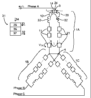
Figure 1 illustrates an embodiment of a multilevel converter according to the
invention. The
multilevel converter of this embodiment is adapted for connecting to a three
phase system and
comprises three legs 1A, 1B, 1C, one leg for each phase A B C, which legs are
connected to-
gether in a star- (or wye-) configuration. Each phase leg 1A-C has one end 3
for connection to
a corresponding phase A-C of a power network, and each phase leg 1A-C has an
opposite end
connected to a common neutral ground point 4, i.e. the phase legs 1A-C share a
common
ground. The neutral ground point 4 is a floating ground and is not connected
to the ground.
Each phase leg, for example 1A, consists of two branches, for example 10 , 20.
For clarity
only the reference numerals for phase leg 1A for phase A have been added to
the figure, but
phases leg 1B and 1C includes the same objects as phase leg 1A. The two
branches 10, 20, of
each phase leg 1A-C are interconnected in its ends, at the first end 3 facing
the power network
and in the second opposite end facing the neutral point 4. Each branch
comprises a series of
switching cells 11, 21. Each branch 10, 20 extends from the neutral 4 to the
phase connection
3, where the two branches of each phase leg 1A-C are joined. Each branch of
each phase leg
is also provided with a reactor 12, 22 arranged at the first end towards the
phase connection 3.
Each reactor 12, 22 functions as a smoothening reactor 12, 22 to even out the
voltage steps of
the power from the branches 10, 20 of each phase leg 1A-C.
The converter also includes a controller 31 operatively connected to the phase
legs, especially
operatively connected (indicated by arrows 32, 33) to the switching cells 11,
21 and includes
means 33 for receiving information from and means 32 for transferring control
signals to each
switching cell 11, 21 individually. The controller 31 is adapted for
monitoring the voltage
(VDc) of each switching cell 11, 21 and adapted for controlling 32 the
switching of each cell
11, 21. The controller 31 is also arranged to monitor 34 the power network,
especially moni-
toring the phase voltages and phase currents.
The controller 31 is adapted to control each phase leg to supply a current II
to the power net-
work by means of switching commands 32 transferred to the switching cells. The
controller is
also adapted to control the phase legs (of each phase) to create a circulating
current Jo in the
phase leg, which circulating current circulates in both branches, from branch
to branch via the
neutral connection 4 and the phase connection 3, without contributing to the
phase current
CA 02852140 2014-04-14
WO 2013/053399
PCT/EP2011/067949
9
The controller comprises a combination of hardware and software to perform its
functions in-
cluding receiving and transferring signals, analysing the signals and
determine voltage levels
and whether a voltage level deviates from nominal ranges. For illustrating the
main character-
istics of the invention, the controller 31 is simplified in the figures 1 and
2. The controller 31
is exemplified as including a current and voltage monitoring part 35, an
analysing part 36 and
a switching cell controlling part 37. The controller 31 receives 34 the phase
voltages and cur-
rents in the power network by means of the monitoring part 35. The controller
31 also re-
ceives 33 the cell voltages and currents in each branch of the converter legs
by means of the
monitoring part 35. The analyser 36 determines if an adjustment is needed, in
which case the
controller 31 starts transferring energy between the energy storage elements
11, 21. The con-
troller 31 performs the switching cells by means of the switching controller
37, and if at least
one voltage should be adjusted, the switching controller 37 adjusts the
switching signals that
are transferred to at least one of the switching cells 11, 21.
The monitoring includes measuring the capacitor voltage VDC of each switching
cell 11, 21,
and the currents created in each phase leg branch Ii0 and 120 respectively.
From the measured
currents Ii0, and 120, the controller 31 is adapted to determine the current
hi provided to the
phase A-C of each respective phase leg 10, 20, and also the circulating
current L. Each phase
leg includes means for monitoring the voltages and currents, such as current
transformers 14,
24 for monitoring each of the branch currents I10, 120, and voltage
transformers for monitoring
each voltage level VDc of each energy storage element. The power exchange with
the power
network is monitored by means of voltage and current measuring devices such as
current
transformers for measuring the phase currents hi of each of the phases and
voltage transform-
ers (not illustrated) for measuring the phase voltages.
Figure 2 illustrates a one phase multilevel converter comprising one single
phase leg 1, which
phase leg has the same topology as each of the three phase legs of the three
phase converter of
figure 1. Thus, the single phase leg comprises two branches 10, 20, each
branch comprising
serially arranged switching cells 11, 21. Each switching cell being
individually controlled by a
controller 31, said controller is provided with means for monitoring 33 and
controlling 32 the
converter, especially controlling the switching of the switching cells 11, 21,
so as to create a
phase current h supplied to the power network and for creating a circulating
current I() that is
not supplied to the power network and instead circulates in the two branches
10, 20 of the
CA 02852140 2014-04-14
WO 2013/053399
PCT/EP2011/067949
single phase leg 1. Each branch 10, 20 of the phase leg 1 also includes a
reactor 12 and 22,
respectively, which reactor 12, 22 is arranged in the network end of the
corresponding branch.
The controller 31 of figure 2 corresponds to the controller of figure 1 and
comprises a combi-
5 nation of hardware and software to perform its functions including
receiving and transferring
signals, analysing the signals and determine voltage levels and whether a
voltage level devi-
ates from nominal ranges. The controller 31 receives 34 the voltage and
current in the power
network by means of the monitoring part 35. The controller 31 also receives 33
the cell volt-
ages (VDC) and currents in each branch of the converter leg 1 by means of the
monitoring
10 part 35. The analyser 36 determines if an adjustment is needed, in which
case the controller
31 starts transfer of energy between the energy storage elements 11, 21. The
controller 31 per-
forms the switching cells by means of the switching controller 37, and if at
least one voltage
should be adjusted, the switching controller 37 adjusts the switching signals
that are trans-
ferred to at least one of the switching cells 11, 21.
Figures 3a and 3b illustrates two embodiments of switching cells (11, 21) and
corresponding
energy storage elements that are suitable for any of the multilevel converter
arrangements of
figures 1 and 2.
Figure 3a illustrates a H-bridge (also referred to as a full bridge) switching
cell. The H-bridge
switching cell includes four IGBTs 41 including freewheeling diodes in anti-
parallel relation-
ship to each respective IGBT. Each cell includes input and output terminals
43, 44 for serial
connection of switching cells to make up a branch of serially connected
switching cells. A
capacitor 42 is arranged as energy storage element, which is selectively
connected to the input
and output terminals 43, 44 by means of the IGBTs.
Figure 3b illustrates a half bridge (also referred to as a half H-bridge)
switching cell. It in-
cludes a capacitor 52 as energy storage element and two IGBTs 51 for selective
connection of
the energy storage element 52 to the terminals 53, 54 of the half bridge
switching cell. Each
switching cell of figures 3a and 3b comprises its own energy storage element
42, 52, the volt-
age of which is monitored for deviations and subsequently adjusted by means of
change of the
switching signal pattern.
CA 02852140 2014-04-14
WO 2013/053399
PCT/EP2011/067949
11
Figure 4 illustrates a method for controlling a multilevel converter. The
method is mainly in-
tended for balancing the DC voltages of the switching cells of the three phase
multilevel con-
verter illustrated in figure 1 and the single phase multilevel converter of
figure 2. The method
includes primarily two main functions illustrated as two parallel sequences.
The method in-
cludes a first sequence including controlling the multilevel converter to
interact with the pow-
er network by supplying power to the network, in steps 101-102, and a second
sequence in-
cluding adjusting the DC voltages of the energy storage elements, in steps 103-
106.
Especially, the method of the invention includes monitoring 105 the voltages
of each energy
storage element, and as a response to the monitoring transferring 107 energy
to, or from, an
energy storage element whose voltage level deviates from predetermined voltage
levels. In
this way the voltage level of every energy storage element can be kept within
suitable limits.
A main function of the multilevel converter is to interact with the power
network; steps 101
and 102 describe this interaction. The method interacts with the power network
by monitoring
the power network, in step 101, which includes monitoring the voltage and
current of each
phase and especially includes monitoring the power supplied to the network.
Also, the interac-
tion includes, in step 102, controlling the power that is supplied from the
converter to the
power network.
The other main function includes the balancing of the DC voltages of the
energy storage ele-
ments of the switching cells. This balancing function is provided by
monitoring the voltage
levels of the energy storage elements in step 105, determining if any of the
voltage levels de-
viates from a nominal voltage level in step 106, and if one or more of the
voltage levels devi-
ate more than a predefined threshold, the method includes the step of
transferring energy to or
from the deviating energy storage element in step 107. This balancing is
performed without
interacting with the power network, so the balancing is performed without
affecting the sup-
ply to the power network. Instead of affecting the interaction with the power
network steps
101, 102 of the method include monitoring and controlling respectively the
interaction with
the power network and maintaining the supply to the power network. Thus, the
energy being
transferred in step 107 is transferred only in the branches within each phase
leg and do not
enter into anyone of the phases of the power network. The embodiment of the
method in fig-
ure 4 also includes monitoring the currents in the branches of each leg in
step 103, especially
monitoring that the energy being transferred by a current in the branches
circulates in the
CA 02852140 2014-04-14
WO 2013/053399
PCT/EP2011/067949
12
closed circuit provided by the two branches of each phase leg. In step 104 the
method in-
cludes controlling the switching elements to create and provide a circulating
current in the
two branches of each phase leg. This circulating current may suitably be
provided as an idling
current circulating in the branches, without adding or subtracting energy from
any of the stor-
age elements unless any of the storage elements should be balanced, i.e. upon
detecting that
an energy storage element deviates and, as a response to the detected
deviation, balancing the
energy storage element in question. The energy transfer step 107 is performed
by adjusting
the already circulating current to add or remove energy from a deviating
switching cell so that
the voltage levels of the energy storage elements are balanced.
The invention has been described mainly by a single phase and a three phase
converter em-
bodiment, and how voltage levels over individual energy storage means can be
kept within
limits so that they do not become too large or too low. The invention can be
used for adjusting
voltage unbalances in a wide range of different multilevel converters acting
for controlling
transmission and distribution of electric power in networks, especially in
multilevel convert-
ers that utilize switching cells with dedicated energy storage elements for
controlling the
power transmission and distribution. Such multilevel converters may be used
for providing
functions including, but not limited to, DC transmission, controlling active
and/or reactive
power, such as reactive power compensation, or for converting AC to DC and DC
to AC.