Sélection de la langue

Search

Sommaire du brevet 2853057 

Énoncé de désistement de responsabilité concernant l'information provenant de tiers

Une partie des informations de ce site Web a été fournie par des sources externes. Le gouvernement du Canada n'assume aucune responsabilité concernant la précision, l'actualité ou la fiabilité des informations fournies par les sources externes. Les utilisateurs qui désirent employer cette information devraient consulter directement la source des informations. Le contenu fourni par les sources externes n'est pas assujetti aux exigences sur les langues officielles, la protection des renseignements personnels et l'accessibilité.

Disponibilité de l'Abrégé et des Revendications

L'apparition de différences dans le texte et l'image des Revendications et de l'Abrégé dépend du moment auquel le document est publié. Les textes des Revendications et de l'Abrégé sont affichés :

  • lorsque la demande peut être examinée par le public;
  • lorsque le brevet est émis (délivrance).
(12) Brevet: (11) CA 2853057
(54) Titre français: COLLECTEUR D'ENERGIE
(54) Titre anglais: ENERGY COLLECTOR
Statut: Périmé et au-delà du délai pour l’annulation
Données bibliographiques
Abrégés

Abrégé français

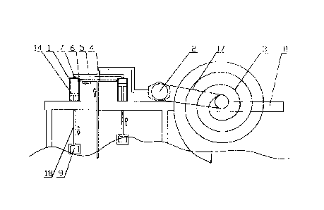
La présente invention a trait à un collecteur d'énergie qui comprend : un vérin hydraulique, un moteur hydraulique et une roue de transport d'eau. Un piston dans le vérin hydraulique est connecté à un dispositif animé d'un mouvement de va-et-vient. Un tuyau d'alimentation en eau et un tuyau de sortie d'eau sont montés sur le vérin hydraulique, un clapet de retenue a est agencé dans le tuyau d'alimentation en eau, un clapet de retenue b est agencé dans le tuyau de sortie d'eau, le tuyau de sortie d'eau est connecté au moteur hydraulique, le moteur hydraulique est connecté à la roue de transport d'eau de manière à assurer la transmission et un tuyau de transport d'eau est monté au centre de la roue de transport d'eau. Une pièce flottante métallique ou un aéromoteur et un disque de rotation sont utilisés de manière à entraîner le vérin hydraulique afin qu'il fonctionne et, par ailleurs, le vérin hydraulique entraîne le moteur hydraulique de sorte que l'eau de mer est transportée au moyen de la roue de transport d'eau et l'énergie potentielle de l'onde ou l'énergie éolienne est convertie en énergie potentielle utilisable de l'eau ; une fois que l'eau de mer entre dans un dispositif de stockage d'eau au moyen de la roue de transport d'eau, l'énergie potentielle de l'eau peut être davantage convertie en énergie mécanique, en énergie pneumatique ou en énergie électrique, ce qui permet de la sorte de convertir l'énergie naturelle en énergie mécanique, en énergie pneumatique ou en énergie électrique en partant du principe qu'aucun gaz à effet de serre n'est émis et que le milieu écologique n'est pas modifié.


Abrégé anglais


The utility model discloses an energy collector, which comprises a hydraulic
cylinder, a hydraulic
motor and a water carrying wheel. A piston in the hydraulic cylinder is
connected with a reciprocating
type running gear; a water inlet pipe and a water outlet pipe are installed on
the hydraulic cylinder; a
one-way valve a is arranged in the water inlet pipe; a one-way valve b is
arranged in the water outlet
pipe; the water outlet pipe is connected with the hydraulic motor; the
hydraulic motor is connected
with the water carrying wheel in a transmission manner; and a water carrying
pipe is installed in the
middle of the water carrying wheel. A metal floating block or a wind wheel and
a turnplate are adopted
in the energy collector to drive the hydraulic cylinder to work; meanwhile,
the hydraulic cylinder
drives the hydraulic motor, and carries seawater out through the water
carrying wheel, and converts
potential energy or wind energy of waves into utilizable potential energy of
water; the seawater after
entering a water storage device can be further converted into mechanical
energy, pneumatic energy or
electric energy, thus realizing to convert natural energy into mechanical
energy, pneumatic energy or
electric energy under the premise of not emitting any greenhouse gases and not
changing the
ecological environment.

Revendications

Note : Les revendications sont présentées dans la langue officielle dans laquelle elles ont été soumises.


CLAIMS
What is claimed is:
1. An energy collector, comprising a hydraulic cylinder (1), a hydraulic motor
(2), a water
carrying wheel (3) and a driving belt (17), wherein a piston (14) in the
hydraulic cylinder (1) is
connected with a reciprocating type running gear; a water inlet pipe (4) and a
water outlet pipe
(5) are installed on the hydraulic cylinder (1); a one-way valve a (6) is
arranged in the water inlet
pipe (4); a one-way valve b (7) is arranged in the water outlet pipe (5); the
water outlet pipe (5) is
connected with the hydraulic motor (2); the hydraulic motor (2) is connected
with the water
carrying wheel (3) through the driving belt (17); and a water carrying pipe
(8) is installed in the
center of the water carrying wheel (3), the water carrying wheel (3) is
provided with a spiral
pipeline, the spiral pipeline having a planar spiral shape with a variable
diameter; the pipeline
connected with the water carrying pipe (8), so that the seawater in the spiral
pipeline is poured
into the water carrying pipe (8) in a planar spiral manner during a rotating
process of the water
carrying wheel (3), thus improving a water level.
2. The energy collector according to Claim 1, wherein the reciprocating type
running gear is
a metal floating block (9); the metal floating block (9) is arranged on a sea
surface and is
connected with the piston (14) through a linkage (18).
3. The energy collector according to Claim 1, wherein the reciprocating type
running gear is
a wind wheel (10) and a turnplate (11); the wind wheel (10) is connected with
a drive rod (13)
through a transmission (12); the turnplate (11) is installed on the bottom of
the drive rod (13); the
piston (14) is hinged with the linkage (18); and the linkage (18) is hinged at
the edge of the
turnplate (11).
4.
The energy collector according to Claim 1, wherein the hydraulic cylinder (1)
is a sleeve
type hydraulic cylinder; the piston (14) is sleeved in a sleeve piston (15);
and the sleeve piston
(15) is sleeved in a cylinder body (16).
6

Description

Note : Les descriptions sont présentées dans la langue officielle dans laquelle elles ont été soumises.


CA 02853057 2014-04-22
ENERGY COLLECTOR
TECHNICAL FIELD
The utility model relates to an energy collector.
BACKGROUND ART
Nowadays, our energy of economy seems to be operated like a perpetuum mobile.
Billions of people
enjoy an unprecedented level of life and countries float in a river of assets,
which are mostly because
that energy industry has established a hugeous network in the whole world that
continuously converts
petroleum and gas hydrocarbon homologies, natural gas and coal into heat and
energy, and endows
mobility of modern civilization. For hundreds of years, utilization of fossil
energy has reached a
saturation state. However, with the gradual depletion of fossil energy
exploitation, development of
human society and industry will stagnate and even hold back. At present,
people start in development
and utilization of new energy, for example, water power plant, tidal power
generation, wind power
generation and the like, most of which convert natural energy into electric
energy; moreover, such a
facility like the water power plant will change the ecology and unknown risks
are hidden. Therefore, it
is in badly need of a device converting natural energy into energy that can be
utilized by people under
the premise of not destroying the environment.
SUMMARY
The utility model aims at providing an energy collector, which adopts maximum
efficiency and
smaller cost to convert natural energy into mechanical energy, pneumatic
energy or electric energy
under the premise of not emitting any greenhouse gas and not changing the
ecological environment.
The objective of the utility model is realized through the following technical
solution.
An energy collector comprises a hydraulic cylinder, a hydraulic motor and a
water carrying wheel. A
piston in the hydraulic cylinder is connected with a reciprocating type
running gear. A water inlet pipe
and a water outlet pipe are installed on the hydraulic cylinder. A one-way
valve a is arranged in the
water inlet pipe, and a one-way valve b is arranged in the water outlet pipe.
The water outlet pipe is
connected with the hydraulic motor. The hydraulic motor is connected with the
water carrying wheel
in a transmission manner. A water carrying pipe is installed in the middle of
the water carrying wheel.
Further, the water carrying wheel is provided with a spiral pipeline. One end
of the pipeline is
connected with the water carrying pipe so that the seawater in the pipeline is
poured into the end of the
water carrying pipe connected with the water carrying pipe in a spiral manner
during a rotating process
of the water carrying wheel, thus improving a water level.
1

CA 02853057 2014-04-22
Further, the reciprocating type running gear is a metal floating block. The
metal floating block is
arranged on a sea surface and is connected with the piston through a linkage.
Further, the reciprocating type running gear is a wind wheel and a turnplate.
The wind wheel is
connected with a drive rod through a transmission. The turnplate is installed
on the bottom of the drive
rod. The piston is hinged with the linkage. The linkage is hinged at the edge
of the turnplate.
Further, the hydraulic cylinder is a sleeve type hydraulic cylinder. The
piston is sleeved in a sleeve
piston. The sleeve piston is sleeved in a cylinder body.
Further, the hydraulic motor is connected with the water carrying wheel
through a driving belt.
The utility model has the advantageous effects that the metal floating block
or the wind wheel and the
turnplate are adopted in the energy collector to drive the hydraulic cylinder
to work; meanwhile, the
hydraulic cylinder drives the hydraulic moto., ¨1.- carries seawater out
through the water carrying
wheel, and converts potential energy or wind energy of waves into utilizable
potential energy of water;
the seawater after entering a water storage device can be further converted
into mechanical energy,
pneumatic energy or electric energy, thus realizing to convert natural energy
into mechanical energy,
pneumatic energy or electric energy under the premise of not emitting any
greenhouse gases and not
changing the ecological environment. A spiral structure is adopted on water
carrying wheel, during
rotating, seawater is collected through a pipeline part at the outermost side,
and the seawater is carried
to the middle of the water carrying wheel through a pipeline the inside of
which retracts to the center in
a spiral manner, thus improving a water level and increasing the seawater
carrying efficiency.
Meanwhile, a telescoping type sleeve hydraulic cylinder is adopted, which
improves the utilization
rate of hydraulic pressure. Meanwhile, an entire system device has simple
elements and high
standardization degree, which effectively reduces the cost, and is convenient
for application and
popularization.
BRIEF DESCRIPTION OF DRAWINGS
The utility model is further detailed hereinafter with reference to the
drawings and embodiments.
FIG. 1 is a structural schematic view of a wave potential energy collector in
an energy collector
according to the utility model;
FIG. 2 is a structural schematic view of a wind energy collector in the energy
collector according to the
utility model;
FIG. 3 is a structural schematic view of installing a piston of the wind
energy collector in FIG. 2;
2

CA 02853057 2014-04-22
s , .
FIG. 4 is a structural schematic view of a telescoping type sleeve hydraulic
cylinder while stretching in
the energy collector according to the utility model; and
FIG. 5 is a structural schematic view of the telescoping type sleeve hydraulic
cylinder while retracting
in the energy collector according to the utility model.
In the FIGs:
1 refers to hydraulic cylinder, 2 refers to hydraulic motor, 3 refers to water
carrying wheel, 4 refers to
water inlet pipe, 5 refers to water outlet pipe, 6 refers to one-way valve a,
7 refers to one-way valve b,
8 refers to water carrying pipe, 9 refers to metal floating block, 10 refers
to wind wheel, 11 refers to
turnplate, 12 refers to transmission, 13 refers to a drive rod, 14 refers to a
piston, 15 refers to a sleeve
piston, 16 refers to a cylinder body, 17 refers to a driving belt, and 18
refers to a linkage
DETAILED DESCRIPTION OF THE EMBODIMENTS
As shown in FIG. 1, the energy collector in the embodiment comprises a
hydraulic cylinder 1, a
hydraulic motor 2 and a water carrying wheel 3. A piston 14 in the hydraulic
cylinder 1 is connected
with a reciprocating type running gear. A water inlet pipe 4 and a water
outlet pipe 5 are installed on
the hydraulic cylinder 1. A one-way valve a6 is arranged in the water inlet
pipe 4, and a one-way valve
b7 is arranged in the water outlet pipe 5. The water outlet pipe 5 is
connected with the hydraulic motor
2. The hydraulic motor 2 is connected with the water carrying wheel 3 through
a driving belt 17. A
water carrying pipe 8 is installed in the middle of the water carrying wheel
3.The water carrying wheel
3 is provided with a spiral pipeline. One end of the pipeline is connected
with the water carrying pipe 8
so that the seawater in the pipeline is poured into the end of the water
carrying pipe connected with the
water carrying pipe in a spiral manner during a rotating process of the water
carrying wheel 3, thus
improving a water level. The reciprocating type running gear is a metal
floating block 9. The metal
floating block 9 is arranged on a sea surface and is connected with the piston
14 through a linkage 18.
As shown in FIG. 2 and FIG. 3, in the embodiment, the reciprocating type
running gear is a wind wheel
and a turnplate 11. The wind wheel 10 is connected with a drive rod 13 through
a transmission 12.
The turnplate 11 is installed on the bottom of the drive rod 13. The piston 14
is hinged with the linkage
18. The linkage 18 is hinged at the edge of the turnplate 11.
As shown in FIG. 4 and FIG. 5, in the foregoing two embodiments, the hydraulic
cylinder 1 is a sleeve
type hydraulic cylinder. The piston 14 is sleeved in a sleeve piston IS. The
sleeve piston 15 is sleeved
in a cylinder body 16.
While working:
3

CA 02853057 2014-04-22
As shown in FIG. 1, in the embodiment, sea wave heaves and drives the metal
floating block 9 to
reciprocate up and down, and enables the piston 14 to reciprocate up and down
in the hydraulic
cylinder 1 through the linkage 18. When the seawater rises, the piston 14
suffers a buoyancy through
the metal floating block 9 and moves upwards. At this time, the one-way valve
b7 is turned on; the
seawater in the hydraulic cylinder 1 enters the water outlet pipe 5.
Meanwhile, the one-way valve a6 is
turned off, and the seawater in the hydraulic cylinder 1 flows back to the
water inlet pipe 4. When the
seawater drops, the piston 14 moves downwards through the gravity of the metal
floating block 9. At
this time, the one-way valve a6 is turned on, and the seawater enters the
hydraulic cylinder 1 through
the water inlet pipe 4. Meanwhile, the one-way valve b7 is turned off, so that
the seawater in the water
outlet pipe 5 will not flow back into the hydraulic cylinder 1.The hydraulic
motor 2 operates through
the seawater outputted from the inside of the water outlet pipe 5, drives the
water carrying wheel 3 to
pour in the seawater through the driving belt 17, enables the seawater to flow
into the middle of the
water carrying wheel 3 through a pipeline inside the water carrying wheel 3
and retracting to the center
in a spiral manner, and enables the seawater to finally flow into a water
storage device through the
water carrying pipe 8.
As shown in FIG. 2, and FIG. 3, in the embodiment, the wind wheel 10 is driven
by wind to rotate, and
is matched with the drive rod 13 through the transmission 12 to transmit
rotation to the turnplate 11.
The turnplate 11 rotates and drives the hinged linkage 18 to rotate
centrifugally. The linkage 18 drives
the piston 14 to reciprocate. When the turnplate 11 rotates and enables the
piston 14 to move upwards,
the one-way valve b7 is turned on at this time, and the seawater in the
hydraulic cylinder 1 enters the
water outlet pipe 5. Meanwhile, the one-way valve a6 is turned off to prevent
the seawater in the
hydraulic cylinder 1 from flowing back into the water inlet pipe 4. When the
turnplate 11 rotates and
enables the piston 14 to move downwards, the one-way valve a6 is turned on at
this time, and the
seawater enters the inside of the hydraulic cylinder 1 through the water inlet
pipe 4. Meanwhile, the
one-way valve b7 is turned off, so that the sea 3 n the water outlet pipe 5
cannot flow back into the
hydraulic cylinder 1. The water outlet pipe 5 is connected with the hydraulic
motor 2 in FIG. 1. The
hydraulic motor 2 operates through the seawater outputted from the water
outlet pipe 5, drives the
water carrying wheel 3 to pure in the seawater through the driving belt 17,
enables the seawater to flow
into the middle of the water carrying wheel 3 through a pipeline inside the
water carrying wheel 3 and
retracting to the center in a spiral manner, and enables the seawater to
finally flow into a water storage
device through the water carrying pipe 8.
4

. CA 02853057 2014-04-22
,
. .
As shown in FIG. 4 and FIG. 5, in the foregoing two embodiments, when the
piston 14 moves upwards,
the piston firstly extrudes the sleeve piston 15 to the inside and then
continuously extrudes the cylinder
body 16 to the inside.
The energy collector adopts maximum efficiency and smaller cost to convert
natural energy into
mechanical energy, pneumatic energy or electric energy under the premise of
not emitting any
greenhouse gas and not changing the ecological environment.

Dessin représentatif
Une figure unique qui représente un dessin illustrant l'invention.
États administratifs

2024-08-01 : Dans le cadre de la transition vers les Brevets de nouvelle génération (BNG), la base de données sur les brevets canadiens (BDBC) contient désormais un Historique d'événement plus détaillé, qui reproduit le Journal des événements de notre nouvelle solution interne.

Veuillez noter que les événements débutant par « Inactive : » se réfèrent à des événements qui ne sont plus utilisés dans notre nouvelle solution interne.

Pour une meilleure compréhension de l'état de la demande ou brevet qui figure sur cette page, la rubrique Mise en garde , et les descriptions de Brevet , Historique d'événement , Taxes périodiques et Historique des paiements devraient être consultées.

Historique d'événement

Description Date
Le délai pour l'annulation est expiré 2018-08-06
Lettre envoyée 2017-08-07
Accordé par délivrance 2016-09-13
Inactive : Page couverture publiée 2016-09-12
Inactive : Taxe finale reçue 2016-06-22
Préoctroi 2016-06-22
Un avis d'acceptation est envoyé 2016-01-20
Lettre envoyée 2016-01-20
Un avis d'acceptation est envoyé 2016-01-20
Inactive : Approuvée aux fins d'acceptation (AFA) 2016-01-18
Inactive : Q2 réussi 2016-01-18
Modification reçue - modification volontaire 2015-10-22
Inactive : Dem. de l'examinateur par.30(2) Règles 2015-04-23
Inactive : Rapport - Aucun CQ 2015-04-22
Inactive : Lettre officielle 2015-03-11
Demande de priorité reçue 2014-07-17
Inactive : Page couverture publiée 2014-07-04
Lettre envoyée 2014-06-19
Requête d'examen reçue 2014-06-16
Exigences pour une requête d'examen - jugée conforme 2014-06-16
Toutes les exigences pour l'examen - jugée conforme 2014-06-16
Inactive : Notice - Entrée phase nat. - Pas de RE 2014-06-06
Inactive : CIB en 1re position 2014-06-05
Inactive : CIB attribuée 2014-06-05
Demande reçue - PCT 2014-06-05
Exigences pour l'entrée dans la phase nationale - jugée conforme 2014-04-22
Déclaration du statut de petite entité jugée conforme 2014-04-22
Demande publiée (accessible au public) 2013-04-25

Historique d'abandonnement

Il n'y a pas d'historique d'abandonnement

Taxes périodiques

Le dernier paiement a été reçu le 2016-07-22

Avis : Si le paiement en totalité n'a pas été reçu au plus tard à la date indiquée, une taxe supplémentaire peut être imposée, soit une des taxes suivantes :

  • taxe de rétablissement ;
  • taxe pour paiement en souffrance ; ou
  • taxe additionnelle pour le renversement d'une péremption réputée.

Les taxes sur les brevets sont ajustées au 1er janvier de chaque année. Les montants ci-dessus sont les montants actuels s'ils sont reçus au plus tard le 31 décembre de l'année en cours.
Veuillez vous référer à la page web des taxes sur les brevets de l'OPIC pour voir tous les montants actuels des taxes.

Historique des taxes

Type de taxes Anniversaire Échéance Date payée
Taxe nationale de base - petite 2014-04-22
Requête d'examen - petite 2014-06-16
TM (demande, 2e anniv.) - petite 02 2014-08-06 2014-08-06
TM (demande, 3e anniv.) - petite 03 2015-08-06 2015-07-06
Taxe finale - petite 2016-06-22
TM (demande, 4e anniv.) - petite 04 2016-08-08 2016-07-22
Titulaires au dossier

Les titulaires actuels et antérieures au dossier sont affichés en ordre alphabétique.

Titulaires actuels au dossier
KAM WA TAI
Titulaires antérieures au dossier
S.O.
Les propriétaires antérieurs qui ne figurent pas dans la liste des « Propriétaires au dossier » apparaîtront dans d'autres documents au dossier.
Documents

Pour visionner les fichiers sélectionnés, entrer le code reCAPTCHA :


Pour visualiser une image, cliquer sur un lien dans la colonne description du document. Pour télécharger l'image (les images), cliquer l'une ou plusieurs cases à cocher dans la première colonne et ensuite cliquer sur le bouton "Télécharger sélection en format PDF (archive Zip)" ou le bouton "Télécharger sélection (en un fichier PDF fusionné)".

Liste des documents de brevet publiés et non publiés sur la BDBC .

Si vous avez des difficultés à accéder au contenu, veuillez communiquer avec le Centre de services à la clientèle au 1-866-997-1936, ou envoyer un courriel au Centre de service à la clientèle de l'OPIC.


Description du
Document 
Date
(aaaa-mm-jj) 
Nombre de pages   Taille de l'image (Ko) 
Dessin représentatif 2014-04-21 1 12
Abrégé 2014-04-21 1 32
Description 2014-04-21 5 266
Dessins 2014-04-21 4 60
Revendications 2014-04-21 1 50
Revendications 2015-10-21 1 46
Dessin représentatif 2016-08-15 1 19
Rappel de taxe de maintien due 2014-06-08 1 111
Avis d'entree dans la phase nationale 2014-06-05 1 192
Accusé de réception de la requête d'examen 2014-06-18 1 175
Avis du commissaire - Demande jugée acceptable 2016-01-19 1 160
Avis concernant la taxe de maintien 2017-09-17 1 178
PCT 2014-04-21 15 600
Correspondance 2014-07-16 3 151
Taxes 2014-08-05 1 25
Correspondance 2015-03-10 1 20
Taxes 2015-07-05 1 25
Modification / réponse à un rapport 2015-10-21 7 316
Taxe finale 2016-06-21 1 44
Taxes 2016-07-21 1 25