Note : Les descriptions sont présentées dans la langue officielle dans laquelle elles ont été soumises.
CA 02854002 2014-04-29
WO 2013/067352 PCT/US2012/063323
ADJUSTABLE VACUUM PAN ASSEMBLIES FOR BELT FILTERS
CROSS-REFERENCE TO RELATED APPLICATIONS
This application claims priority to US Provisional Patent Application Serial
No.
61/555,040 filed on 3 November 2011.
BACKGROUND OF THE INVENTION
This invention relates to filtration processes and equipment, and more
particularly to
horizontal belt filter apparatus, particularly for use in minerals processing.
FIGS. 1, 2, and 4 show a horizontal belt filter 900 having a conventional
vacuum pan
assembly 990. Horizontal belt filter 900 comprises a frame 930, a plurality of
return rollers 920
and a drainage belt 910 having a number of pores 912 provided therein which
are configured to
pass fluid and moisture from a slurry (not shown) to the conventional vacuum
pan assembly 990
positioned below the belt 910. Belt 910 supports filter media 914 such as a
filter cloth.
Conventional vacuum pan assembly 990 comprises a swing arm 940 which is
pivotally attached
to said frame 930 by way of a pivot bracket 941 having a first pivot member
946, and a second
pivot member 936 provided to the frame 930. A vacuum pan 950 having an
elongated inlet 951
and a channel 952 is mounted to the swing arm 940 via a number of fasteners
953 passing
through at least one mount 957 on the pan 150. A wear plate 959 having a
number of apertures
955 may serve as a sacrificial interface between the pan 150 and the belt 910.
Apertures 955 in
the wear plate 959 allow fluid and moisture from slurry passing through pores
912 to enter the
conventional vacuum pan assembly 990 positioned below the belt 910. A first
securing portion
944 is provided to a distal end of the swing arm 940, opposite the pivot
bracket 941 and the first
pivot member 946. The first securing portion 944 is configured to mate with a
complementary
second securing portion (not shown) provided at a predetermined location on
the frame 930 of
the filter 900. Engagement between the first securing portion 944 and the
second securing
1
CA 02854002 2014-04-29
WO 2013/067352 PCT/US2012/063323
portion (not shown) serves to keep vacuum pan 950 and wear plate 959 in close
communication
with belt 910.
As best shown in FIGS. 2 and 3, at least one shim 960 is typically placed
between the
swing arm 940 and mount 957 to better align the inlet 951 of the pan 950 with
the pores 912 in
the belt 910 and sometimes to adjust the tilt of the pan 950 to match an
inclination of the belt
910. The exact number and/or configuration of shims 960 may vary between each
swing arm
940 and mount 957 along the length of the filter 900, and will frequently
change as portions of
wear plate 959 dimensionally change (e.g., in thickness) due to continued
friction with the belt
910.
A significant disadvantage of using shims 960 is that when used wear plates
959 are
replaced with thicker new wear plates (or when any portion of the conventional
vacuum pan
assembly 990 such as the pan 950 itself needs to be removed for routine
maintenance or
cleaning), there is no simple way to restore the position of the pan 950 to a
"factory default"
alignment configuration with respect to the swing arm 940. In other words,
shims 960 necessary
for use with thin worn wear plates 959, which are removed from the assembly
990 to
accommodate thick new wear plates 959, will need to be replaced in a new
configuration in a
lesser number in order to bring the pan 950 into proper re-alignment with the
belt 910. Such re-
configuring and adjustment steps require unnecessary downtime and labor.
To add to the abovementioned problem, shims are typically custom-fabricated at
each
shim location. Multiple shims of varying thickness are required at each shim
point to achieve the
desired elevation required for belt-to-pan alignment and proper vacuum seal
between the belt
910 and vacuum pan assembly 990. Shims 960 are frequently lost, mixed up or
accidentally
2
CA 02854002 2014-04-29
WO 2013/067352 PCT/US2012/063323
confused with other shims 960, and additional shims 960 may need to be quickly
fabricated and
provided in the field in order to adjust the positioning of the vacuum pan 950
during routine
maintenance.
Jack screws often "seize" in place after a short time in operation, thereby
resulting in the
inability to adjust the elevation or removal of vacuum pan 950 during routine
maintenance.
Neither shims 960 or jack screws (not shown) provide a quick and efficient way
to re-establish
"factory-set elevation points" for a vacuum pan 950 after maintenance
adjustments are
.performed.
Conventionally, the horizontal adjustment of vacuum pans 950 typically
involves
welding an adjusting plate (not shown) to the swing arm in-situ during
assembly. As a result of
in-situ welding, additional cleaning of the weld area and protective
repainting is required. These
extra steps add to the total commissioning time and cost. Moreover, welding
exposes expensive
components (e.g., belt 910) to potential damage.
OBJECTS OF THE INVENTION
It is, therefore, an object of the invention to provide a vacuum pan assembly
which
reduces down time for users during routine maintenance.
It is also an object of the invention to provide a vacuum pan assembly which
requires less
shop assembly time and does not require welding and subsequent protective
painting.
It is also an object of the invention to provide a vacuum pan assembly
adjustment
mechanism which is easily adapted for and configured to be used with current
filters using shims
and jacks, thereby providing a valuable aftermarket conversion kit.
3
CA 02854002 2014-04-29
WO 2013/067352 PCT/US2012/063323
It is also an object of the invention to provide a device which enables a user
of a filter to
adjust a vacuum pan both vertically and horizontally using a single mechanism.
It is also an object of the invention to provide adjustment means to a vacuum
pan which
allows horizontal adjustment without the need for a providing a separately-
welded adjusting
plate, and welding in assembly.
These and many other objects of the invention will be apparent from the
drawings and
description herein. Although every object of the invention is believed to be
attained by at least
one embodiment of the invention, there is not necessarily any one embodiment
of the invention
that achieves all of the objects of the invention.
SUMMARY OF THE INVENTION
An adjustable vacuum pan assembly for a belt filter is disclosed. The
adjustable vacuum
pan assembly comprises an arm configured to be attached to a frame portion of
the filter, a
vacuum pan adjustably connected to the arm, and a cam operatively coupled to
the arm. The arm
may comprise a swing arm which is pivotally attached to said frame portion of
the belt filter.
The cam is rotatable with respect to the arm and has a peripheral surface
which contacts a
portion of the vacuum pan. The assembly further comprises a locking member
which serves to
hold the cam against rotation with respect to the arm. Varying an angular
rotational position of
the cam effectively varies a spacing between the vacuum pan and the arm,
thereby providing an
amount of misalignment compensation therebetween. In some embodiments, the cam
is
operatively coupled to the arm via a bracket which may be adjustably
positionable with respect
to the arm in at least one direction. In some embodiments, the locking member
selectively
4
CA 02854002 2014-04-29
WO 2013/067352 PCT/US2012/063323
engages one of a plurality of engagement surfaces on the cam to maintain a
spacing between the
vacuum pan and the arm. In some embodiments, means for applying a torque to
the cam is
provided. In some embodiments, the cam rotates about an axis defined by a pin,
and the
position of the cam along said axis may be adjusted and then limited or
maintained by a stop one
or more retainers.
A belt filter is also disclosed, wherein the belt filter comprises an
adjustable vacuum pan
assembly as described above.
A retrofit kit for a filter is also disclosed. The kit comprises a bracket
configured to be
mounted to an arm or other frame portion of a filter, a cam configured to be
operatively coupled
to said bracket, and a locking member configured to hold the cam against
rotation with respect to
the bracket. The arm may comprise a swing arm which is pivotally attached to
said frame
portion of the belt filter. The cam is rotatable with respect to the bracket
and has a peripheral
surface which is configured to contact a portion of a vacuum pan or other
component. In use,
varying an angular rotational position of the cam effectively varies a spacing
between a vacuum
pan and said bracket, thereby providing an amount of misalignment compensation
therebetween.
Also disclosed is a method of providing increased adjustability to a
conventional vacuum
pan assembly in a filter. The method comprises the steps of providing a cam to
an arm or frame
portion of a filter, providing a locking member to hold the cam against
rotation with respect to
the arm or frame portion, varying an angular rotational position of the cam to
effectively vary a
spacing between a vacuum pan and the arm or frame portion, thereby providing
an appropriate
amount of misalignment compensation therebetween, locking the cam from
rotation using the
CA 02854002 2015-03-23
54408-37
locking member, and maintaining an appropriate spacing between a vacuum pan
and said arm
or frame portion during operation of said filter.
According to one aspect of the present invention, there is provided a belt
filter
having an adjustable vacuum pan assembly, the adjustable vacuum pan assembly
comprising:
an arm attached to a frame portion of the belt filter; a vacuum pan adjustably
connected to the
arm; a cam operatively coupled to the arm, the cam being rotatable with
respect to the arm
and having a peripheral surface which contacts a portion of the vacuum pan;
and a locking
member configured to hold the cam against rotation with respect to the arm;
wherein varying
an angular rotational position of the cam effectively varies a spacing between
the vacuum pan
and the arm thereby providing an amount of misalignment compensation
therebetween.
According to another aspect of the present invention, there is provided an
adjustable vacuum pan assembly comprising: an arm configured to be attached to
a frame
portion of a filter; a vacuum pan adjustably connected to the arm; a cam
operatively coupled
to the arm, the cam being rotatable with respect to the arm and having a
peripheral surface
which contacts a portion of the vacuum pan; and a locking member configured to
hold the
cam against rotation with respect to the arm; wherein varying an angular
rotational position of
the cam effectively varies a spacing between the vacuum pan and the arm
thereby providing
an amount of misalignment compensation therebetween.
According to another aspect of the present invention, there is provided a kit
for
providing increased adjustability to a conventional vacuum pan assembly the
kit comprising: a
bracket configured to be mounted to an arm or frame portion of a filter; a cam
configured to
be operatively coupled to said bracket, the cam being rotatable with respect
to the bracket and
having a peripheral surface which is configured to contact a portion of a
vacuum pan; and a
locking member configured to hold the cam against rotation with respect to the
bracket;
wherein in use, varying an angular rotational position of the cam effectively
varies a spacing
between a vacuum pan and said bracket, thereby providing an amount of
misalignment
compensation therebetween.
6
CA 02854002 2015-03-23
54408-37
According to another aspect of the present invention, there is provided a
method of providing increased adjustability to a conventional vacuum pan
assembly in a filter
comprising: providing a cam to an arm or frame portion of the filter, the cam
being rotatable
with respect to the swing arm or frame portion and having a peripheral surface
which is
configured to contact a portion, component, or adapter of a preexisting
conventional vacuum
pan; providing a locking member to hold the cam against rotation with respect
to the arm or
frame portion ; varying an angular rotational position of the cam to
effectively vary a spacing
between a vacuum pan and the arm or frame portion, thereby providing an
appropriate amount
of misalignment compensation therebetween; locking the cam from rotation using
the locking
member; and maintaining an appropriate spacing between a vacuum pan and said
arm or
frame portion.
BRIEF DESCRIPTION OF THE DRAWINGS
FIG. 1 is an end cross-sectional view of a conventional horizontal belt
filter;
FIG. 2 is a detailed end view of a vacuum pan of the belt filter shown in
FIG. 1;
FIG. 3 shows an adjustable vacuum pan according to some embodiments;
FIG. 4 is a side view of the conventional vacuum pan shown in FIG. 1;
FIG. 5 is a side view of the adjustable vacuum pan shown in FIG. 3;
FIG. 6 is a detailed exploded view of the adjustable vacuum pan shown in
FIG. 3;
FIG. 7 is an isometric cross-sectional view of the adjustable vacuum pan
shown in FIG. 3; and,
FIG. 8 is broad isometric view of the adjustable vacuum pan shown in FIG. 3.
6a
CA 02854002 2015-03-23
54408-37
DETAILED DESCRIPTION OF THE INVENTION
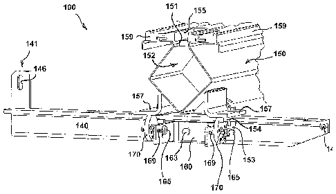
FIGS. 3 and 5-8 show an improved adjustable vacuum pan assembly 190. The
vacuum pan assembly 190 comprises a swing arm 140 which is pivotally attached
to a frame
portion of a filter 900 (e.g., a horizontal belt filter). Swing arm 140
comprises a pivot bracket
141 having a first pivot member 146 configured to communicate with a second
pivot member
936 such as a pin, dowel, hinge, fulcrum, or other equivalent device provided
to the frame 930
of the filter 900. In the exemplary embodiment shown, first pivot member 146
is provided as
an aperture suitable
6b
CA 02854002 2014-04-29
WO 2013/067352 PCT/US2012/063323
for receiving a pin or rod; however, the first pivot member 146 may equally be
a portion of a
hinge or other pivoting mechanism without limitation. A vacuum pan 150 having
one or more
effluent ports 158, an elongated inlet 151, and a channel 152 suitable for
collecting, retaining,
and delivering fluid and moisture is mounted to the swing arm 140 via at least
one fastener 153
passing through at least one mount 157 on the pan 150. One or more wear plates
159 having a
number of apertures 155 may serve as a sacrificial interface between the pan
150 and a belt 910.
Apertures 155 in each wear plate 159 allow fluid and moisture passing through
pores 912 of a
belt 910 to enter the vacuum pan assembly 190 positioned below the belt 910.
While not shown,
it is envisaged that each wear plate 159 may alternatively comprise two
parallel wear plates
having therebetween, a spacing which similarly allows fluid to pass. A first
securing portion 144
is provided to a distal end of the swing arm 140, opposite the pivot bracket
141 and first pivot
member 146. The first securing portion 144 is configured to mate with a
complementary second
securing portion (not shown) provided at a predetermined location on the frame
930 of a filter
900. Engagement between the first securing portion 144 and the second securing
portion (not
shown) serves to keep vacuum pan 150 and wear plate 159 in close communication
with belt
910.
Fine adjustability of spacing between the pan 150 and the swing arm 140 is
achieved through
the use of at least one cam 170 which initially supports the mount 157 of the
pan 150 in at least a
Z-axis direction extending between an upper and lower portion of the filter
900. Cam 170 is
rotatable through a range of motion in at least one rotational degree of
freedom. The at least one
rotational degree of freedom is shown to be about an axis which is generally
parallel with a long
axis of the swing arm 140 extending between the pivot bracket 141 and first
securing portion
7
CA 02854002 2014-04-29
WO 2013/067352 PCT/US2012/063323
144. However, while not shown, said at least one rotational degree of freedom
may alternatively
be about an axis which is generally perpendicular with respect to a long axis
of the swing arm
140 as will be described in more detail below. In some preferred embodiments,
the cam 170 is
round and allows independent vertical adjustment of the pan 150 in the Z-axis
direction in 0.5-
5mm increments, and even more preferably between lmm and 3mm increments - for
example,
1.5mm increments.
Swing arm 140 comprises a set of one or more oblong openings 142 which may
extend
longitudinally in an X-axis direction within an X-Z plane which is generally
transverse to the
filter 900. One or more fasteners 163 extend through said oblong openings 142
and hold a
bracket 160 to the swing arm 140. The elongated nature of the oblong openings
142 allows
bracket 160 to be mounted to the swing arm 140 with some amount of positional
adjustability in
at least said X-axis direction. In the embodiment shown, bracket 160 comprises
a set of one or
more openings 161 which are configured to receive the fasteners 163. However,
it is
contemplated that while not shown, oblong openings 142 may instead be provided
on the bracket
160, and openings 161 may be provided to the swing arm 140. Moreover, other
means for X-
axis positional adjustment may be provided, including, but not limited to:
tracks, channels,
sliding dovetail joints, linear bearings, or the like.
Swing arm 140 further comprises a set of one or more oblong openings 143 which
may
extend longitudinally in an X-axis direction within an X-Y plane which is
generally parallel to
belt 910. One or more fasteners 153 extend through said oblong openings 143
and hold mount
157 to the swing arm 140. The elongated nature of the oblong openings 143
allows pan 150 to
be mounted to the swing arm 140 with some amount of positional adjustability
in at least the X-
8
CA 02854002 2014-04-29
WO 2013/067352 PCT/US2012/063323
axis direction. Similarly, one or more mounts 157 provided to the vacuum pan
150 may
comprise a set of one or more oblong openings 156 which may extend
longitudinally in a Y-axis
direction within said X-Y plane. Fasteners 153 extend through said oblong
openings 143, 156
and secure the mount 157 (and therefore, pan 150) to the swing arm 140. The
elongated nature
of the oblong openings 156 allows pan 150 to be mounted to the swing arm 140
with some
amount of positional adjustability in at least the Y-axis direction. While not
shown, it is
contemplated that oblong opening sets 143 and 156 may be interchanged without
negatively
affecting function. Moreover, oblong openings 143, 156 may be collectively
replaced with other
means for X-Y planar positional adjustment including, but not limited to:
perpendicular tracks,
perpendicular channels, perpendicular sliding dovetail joints, planar
bearings, etc. While
specifically shown as nuts and bolts, it should be noted that fasteners 153,
163 according to the
invention may be of any suitable type including, but not limited to: headed
rivets, clevis pins,
weld studs, and the like.
Bracket 160 comprises a pin 165 which is configured to receive a cam 170 via
an
aperture 177 provided to said cam 170 which is offset of center (i.e., the cam
170 is eccentric).
Pin 165 may be modular (e.g., provided as a bolt secured to the bracket 160
with a nut), or pin
165 may be permanently attached to the bracket (e.g., a weld stud).
A torque boss 171 may be provided to the cam 170. In some embodiments, torque
boss
171 is concentric or otherwise co-axial with said aperture 177. Cam 170
further comprises a
plurality of engagement surfaces 178 which are displaced various distances
from said aperture
177 and are positioned at different locations relative to the aperture 177.
The engagement
surfaces 178 are configured to accept a locking member 169 which is adapted to
fix the cam 170
9
CA 02854002 2014-04-29
WO 2013/067352 PCT/US2012/063323
in place in at least 5 degrees of freedom with respect to the bracket 160. In
the very least,
locking member 169 prevents a rotational movement of the cam 170. In some
embodiments,
cam 170 may be permitted to move in a direction along the axis of pin 165 and
aperture 177 (i.e.,
in an X-axis direction) and contact a stop 154 provided on the pan 150 or pan
mount(s) 157 or
other portion of the assembly 190 in order to limit lateral movement of the
cam 170. Smooth
peripheral surfaces on the cam 170 enable some amount of horizontal
displacement of the cam
170 in the X-axis direction or Y-axis direction, without affecting the
vertical positioning of the
vacuum pan 150 in the Z-axis direction, thereby eliminating the need for an
additional adjusting
plate and the step of welding said adjusting plate to the assembly 990 in-
situ. If desired, the cam
170 may be fixed in 6 degrees of freedom relative to the swing arm 140 by one
or more retainers
164, 166 located on either side of the cam. As shown, in some embodiments,
retainers 164, 166
may comprise threaded lock nuts which engage threads provided to pin 165. In
other
embodiments (not shown), retainers 164, 166 may comprise internal lock washers
having biting
teeth in the internal diameter surfaces which lock to pin 165 when axially
pressed axially onto
pin 165. In yet even other embodiments, retainers 164, 166 may comprise small
locking detent
pins, positive lock pins, or set screws which transversely engage the pin 165.
In use, an operator inputs a torque on the torque boss 171, which in turn
rotates cam 170
about pin 165. Outer peripheral surfaces of cam 170 ride/slide along mount
157, which acts as a
"follower". As cam 170 is rotated, pan 150 moves up or down in a Z-axis
direction, thereby
increasing or decreasing a distance between the belt 910 and the adjustable
vacuum pan
assembly 190. Once the desired position of the adjustable vacuum pan assembly
190 is set in the
Z-axis direction, the spacing between belt 910 and wear plate 159 can be
reversibly set in place
CA 02854002 2014-04-29
WO 2013/067352 PCT/US2012/063323
by engaging a locking member 169 with one of the engagement surfaces 178
provided on the
cam 170. Engagement surfaces 178 are preferably marked with indicia to
indicate factory set
points and indicate an amount of adjustment (e.g., in millimetres). This
eliminates the need for a
maintenance worker to go through several step iterations to realign the vacuum
pan 150
following routine maintenance or disassembly.
In the particular embodiment shown, engagement surfaces 178 are apertures
which are
configured to receive a locking member 169 in the form of a pin. At least one
oblong opening
167 may extend longitudinally in a Y-axis direction in a median/sagittal Y-Z
plane. Locking
member 169 may extend through said oblong opening 167 and thereby hold cam 170
against
rotational freedom about pin 165. Securement of locking member 169 may be
facilitated by a
retainer 162 provided on both an inside portion of bracket 160, and an outside
portion of bracket
160, wherein the retainers 162 communicate with the locking member 169 and
sandwich the
oblong opening 167 and cam 170 therebetween. Consequently, pan 150 may be
propped up to a
desired elevation with respect to the belt 910 in at least a Z-axis direction.
The elongated nature of the one or more oblong openings 167 allows cam 170 to
be
fixedly positioned to the bracket 160 in a plurality of rotational angles
utilizing a "peg-in-hole"
configuration. However, while not shown, it is contemplated that oblong
opening 167, retainer
169, and engagement surfaces 178 may be replaced with other means for securing
against
rotation of the cam 170 about pin 165, including, but not limited to: pawl and
ratchet systems,
worm drives (e.g., wherein peripheral cam surfaces are toothed), clamp
members, and/or semi-
permanent tack welds or other form of reversible or temporary adhesive
bonding. While
specifically shown as clips, it should be noted that retainers 162 according
to the invention may
11
CA 02854002 2014-04-29
WO 2013/067352 PCT/US2012/063323
be of any suitable type including, but not limited to: headed rivets, clevis
pins, set screws, and
the like.
Once the Z-axis position of the pan 150 is set by cam 170 and fixed by locking
member
169, fastener 153 may be fully tightened or otherwise engaged to further
secure the pan 150 to
the swing arm 140 in at least a Z-axis direction. However, prior to setting
fastener 153, small
horizontal positional adjustments of the vacuum pan 150 relative to belt 910
may be made by
loosening fasteners 153, 163 and subsequently sliding bracket 160 along the
swing arm 140 in
the X-axis direction, wherein the fasteners 163, 153 slide in oblong openings
142, 143,
respectively. The bracket 160 and pan 150 may then be fixed into place with
respect to the
swing arm 140 by tightening fasteners 153, 163.
Alternatively, and more preferably, horizontal positional adjustments of the
vacuum pan
150 relative to belt 910 may be made by loosening fastener 153 and
subsequently sliding pan 150
along the swing arm 140 in the X-axis direction to a desired location, wherein
the fasteners 153
slide in oblong openings 143 of the swing arm 140. Securement of the pan 150
with respect to
the swing arm 140 begins by tightening fasteners 163 so as to secure bracket
160 to swing arm
140. Retainers 164. 166 provided on pin 165 which extends from the bracket 160
are positioned
along the pin 165 in an X-axis direction so as to move cam 170 laterally
against stop 154. Forces
acting in the X-axis direction are applied to the stop 154 by the cam 170 and
move or bend the
pan 150 into longitudinal alignment with pores 912 in the belt 910. The Z-axis
position of the
pan 150 may then be set by rotating cam 170 about pin 165 to a desired
location, and then fixing
the rotational position of cam 170 with locking member 169. Thereafter,
fastener 153 may be
12
CA 02854002 2014-04-29
WO 2013/067352 PCT/US2012/063323
fully tightened or otherwise engaged to secure the pan 150 to the swing arm
140 in at least a Z-
axis direction.
A contractor or other entity may provide a belt filter, vacuum pan assembly,
or
component of vacuum pan assembly, or operate a belt filter or vacuum pan
assembly in whole, or
in part, as shown and described. For instance, the contractor may receive a
bid request for a
project related to designing or operating a belt filter or vacuum pan
assembly, or the contractor
may offer to design such a system or a process for a client. The contractor
may then provide, for
example, any one or more of the devices or features thereof shown and/or
described in the
embodiments discussed above. The contractor may provide such devices by
selling those
devices or by offering to sell those devices. The contractor may provide
various embodiments
that are sized, shaped, and/or otherwise configured to meet the design
criteria of a particular
client or customer. The contractor may subcontract the fabrication, delivery,
sale, or installation
of a component of the devices disclosed, or of other devices used to provide
said devices. The
contractor may also survey a site and design or designate one or more storage
areas for stacking
the material used to manufacture the devices, or for storing the devices
and/or components
thereof. The contractor may also maintain, modify, or upgrade the provided
devices. The
contractor may provide such maintenance or modifications by subcontracting
such services or by
directly providing those services or components needed for said maintenance or
modifications,
and in some cases, the contractor may modify a preexisting conventional
filter, vacuum pan
assembly, or parts thereof with a "retrofit kit" to arrive at a modified
filter system comprising
one or more method steps, devices, components, or features of the systems and
processes
discussed herein.
13
CA 02854002 2014-04-29
WO 2013/067352 PCT/US2012/063323
Although the invention has been described in terms of particular embodiments
and
applications, one of ordinary skill in the art, in light of this teaching, can
generate additional
embodiments and modifications without departing from the spirit of or
exceeding the scope of
the claimed.
For example, it is envisaged that swing arm 140 and corresponding vacuum pan
150 may
comprise different shapes and sizes depending on the overall size and design
specifications of a
filter 900. Moreover, while oblong openings 142, 143, 156, 167 are primarily
shown in the
drawings as through holes, oblong openings may be blind openings and/or may
comprise any
one or more of the following without limitation: cutouts, a series of closely-
spaced non-oblong
apertures (threaded or non-threaded), notches, detent configurations, pockets,
pawl and ratchet
adjustment mechanisms, grooves, channels, depressions, dovetails, and/or
undercuts. Similarly,
male members shown herein such as locking member 169 may comprise threads, for
example, in
the form of a set screw.
Furthermore, features and components of the adjustable vacuum pan assembly 190
may
be modular, removable, "bolt-on", or "weld-on" components which are provided
individually or
collectively within a "retrofit kit". Such components may therefore be
interchanged with or
added to preexisting conventional vacuum pan assemblies 990 to achieve the
benefits of the
invention. In some instances, a retrofit kit may comprise one or more mounts
157 or adapters to
accommodate preexisting conventional mounts 957. Said adapters can be bolted
or welded to
preexisting conventional mounts 957 or other portions of a preexisting
conventional vacuum pan
950. Such adapters may comprise one or more stops 154, additional flanges or
flange extenders,
14
CA 02854002 2014-04-29
WO 2013/067352 PCT/US2012/063323
extension members, spacers, or one or more universal mounting features such as
oblong
openings 156 which are configured to accept at least one fastener 153.
It should be known that in some embodiments, torque boss 171 may be eliminated
in
favor of other means for applying a torque to the cam 170. Such means may
comprise, for
instance, torque-application surfaces provided as one or more "flats" which
are located at
selected peripheral locations of the cam 170. Such means may also comprise a
lever or handle
which extends from the cam, or a peripheral cavity which is engagable by a
separate torque arm
or cheater bar.
It is contemplated that in some embodiments, male and female components
disclosed
herein may be reversed and still be within the scope of the disclosure. For
example, male pin
165 provided to bracket 160 and female aperture provided to cam 170 may be
reversed so that
the pin 164 extends from the cam 170 and into the bracket 160. Similarly,
while engagement
surfaces 178 are shown to be provided on the cam 170, and oblong opening 167
is shown to be
provided on the bracket 160, the two may obviously be reversed such that the
engagement
surfaces are provided on the bracket 160, and oblong opening 167 is provided
on the cam 170.
Moreover, the joining of fasteners 153, 163 may be accomplished using threaded
connections, plastic deformation, welding, gluing, combinations thereof, or
other equivalent
means without limitation. Mounts 157 and/or fasteners 153, 163 may be provided
in any number
or configuration which is suitable for the intended purpose. As shown in FIGS.
7-8, brackets
160 according to the invention may further comprise one or more wear belt
guides 180 ¨ each
having one or more rollers or bearing members 182 provided thereon to provide
support and/or
CA 02854002 2014-04-29
WO 2013/067352 PCT/US2012/063323
lateral guidance for a wear belt (not shown) which travels within upper
grooves formed in wear
plate 159 and contacts belt 910.
Furthermore, the number and configuration of components described may vary.
For
instance, while two cams 170 are shown in FIGS. 4-8, a single cam 170 or more
than two cams
170 may be employed without departing from the scope of the invention.
Moreover, while cams
170 are shown to be mounted to the swing arm 140, they may inversely be
connected to mounts
157, wherein peripheral surfaces of the cam 170 engage a portion of the swing
arm 140 to
effectively vary a spacing therebetween. Alternatively, cams 170 may be
provided to the swing
arm 140 directly, without the need for a bracket 160. This may be
accomplished, for example,
by orienting the cam 170 ninety degrees from what is shown in the drawings, so
that it is parallel
to the swing arm 140, providing pin 165 directly to the swing arm 140 ¨ on
which the cam 170
rotates, and providing a locking member 169 which engages or otherwise
communicates with the
swing arm 140 to prevent rotation of the cam 170 relative to the swing arm
140.
In some instances, swing arm 140 may comprise a portion of a linkage (e.g., of
the four-
bar type), which moves pan 150 up and down in a Z-axis direction. Or the swing
arm 140 may
be configured to "tilt" or pivot with respect to the belt 910 and travel in an
arcuate transverse
path as shown. Additionally, bracket 160 may be mounted to other types of
vacuum pan 150
raising and lowering systems such as those disclosed in US Patent Nos. US-4,
336, 139, US-
4,080,298, US-3,992,298, and US-4,671,876. In some instances, swing arm 140
may not
necessarily be configured to "swing" at all. In other words, it is envisaged
that an "arm", where
the term is used herein, may simply comprise a static portion of a filter's
frame 930, or may
comprise an arm 140 which is connected at both ends to other frame portions
930. Such
16
CA 02854002 2014-04-29
WO 2013/067352 PCT/US2012/063323
connections may be realized using welding, bolting, or adjustable mounting
means. The arm 140
may also be moved linearly in a Z-axis direction with respect to said belt 910
without swinging,
for example, via the use of one or more mechanical actuators, compressible or
incompressible
fluid cylinders, or electric solenoids. In some embodiments, arm 140 may ride
on a track, and
cams 170 may be fixed to frame portions 930 which are adjacent to end portions
of the arm 140.
Z-axis positioning and tilt of the arm 140 with respect to frame 930 may be
adjusted by rotating
and then subsequently immobilizing the cams 170 relative to the frame 930
using a locking
member 169.
It should also be noted that while shown specifically on a horizontal belt
filter 900,
adjustable vacuum pan assemblies 190 of the invention may be used in other
applications
requiring quick fine adjustment between two adjacent components. For example,
assemblies 190
and components thereof which are shown and described herein may have equal
applicability on
table filters and belt filter presses.
Accordingly, it is to be understood that the drawings and descriptions herein
are proffered
by way of example to facilitate comprehension of the invention and should not
be construed to
limit the scope thereof.
17
CA 02854002 2014-04-29
WO 2013/067352
PCT/US2012/063323
Reference numeral identifiers
900 Filter
910 Drainage belt
912 Pores
914 Filter media
920 Return roller
930 Frame
936 Second pivot member
940 Swing arm
941 Pivot bracket
944 First securing portion
946 First pivot member
950 Pan
951 Inlet
952 Channel
953 Fastener
955 Aperture
957 Mount
959 Wear plate
960 Shim
990 Conventional vacuum pan assembly
140 Swing arm
141 Pivot bracket
142 Oblong opening (X-axis direction)
143 Oblong opening (X-axis direction)
144 First securing portion
146 First pivot member
150 Pan
151 Inlet
152 Channel
153 Fastener
154 Stop
155 Aperture
156 Oblong opening (Y-axis direction)
157 Mount
158 Port
159 Wear plate
160 Bracket
161 Opening
162 Retainer
163 Fastener
164 Retainer
165 Pin
166 Retainer
167 Oblong opening (Y-axis direction)
169 Locking member
170 Cam
171 Torque boss
177 Aperture
178 Plurality of engagement surfaces
180 Wear belt guide
182 Roller or bearing member
190 Adjustable vacuum pan assembly
18