Note : Les descriptions sont présentées dans la langue officielle dans laquelle elles ont été soumises.
CA 02854356 2014-05-01
WO 2013/074968 PCMJS2012/065591
FIRE BARRIER LAYER AND FIRE BARRIER FILM LAMINATE
A fire barrier laminate is provided for use in thermal and acoustical
insulation
systems, such as, but not limited to, those used in commercial aircraft.
The Federal Aviation Administration (FAA) has promulgated regulations,
contained in 14 C.F.R. 25.856(a) and (b), requiring thermal and acoustical
insulation
blanket systems in commercial aircraft to provide improved bum through
protection and
flame propagation resistance. These conventional thermal and acoustical
insulation
systems typically include thermal and acoustical insulation blankets
encapsulated within a
film covering or bag. As the thermal and acoustical insulation systems are
conventionally
constructed, the bum through regulations primarily affect the contents of the
insulation
systems' bags and the flame propagation resistance regulations primarily
affect the film
coverings used to fabricate the bags. Conventional film coverings typically
are used as a
layer or covering, for example, laid over or laid behind layers of thermal and
acoustical
insulation material, or as a covering or bag for partially or totally
encapsulating one or
more layers of thermal and acoustical insulation material.
FIG. 1A is a schematic cross-sectional view of a thermal and acoustical
aircraft
insulation blanket protected by an embodiment of the subject fire barrier
laminate.
FIG. 1B is an exploded cross-sectional view of the subject fire barrier
laminate
circled portion B' of the embodiment of FIG. 1A.
FIG. 1C is an exploded cross-sectional view of another illustrative embodiment
of
the subject fire barrier laminate circled portion B' of the embodiment of FIG.
1A.
FIG. 1D is an exploded cross-sectional view of a further illustrative
embodiment
of the subject fire barrier laminate circled portion B' of the embodiment of
FIG. 1A.
FIG. lE is an exploded cross-sectional view of a further illustrative
embodiment
of the subject fire barrier laminate circled portion B' of the embodiment of
FIG. 1A.
1
CA 02854356 2014-05-01
WO 2013/074968 PCT/US2012/065591
A fire barrier layer is provided which is incorporated into a fire barrier
laminate
for use in thermal and acoustical insulation systems, such as, but not limited
to, those
used in commercial aircraft. By way of example, but not limitation, the fire
barrier
laminate may be used as a covering that is located between insulation material
in fuselage
wall cavities and the outer skin of an aircraft fuselage (as an outboard cover
of an
insulation system) and/or between insulation material in fuselage wall
cavities and the
interior aircraft trim panels (as an inboard cover of an insulation system).
The incorporation of the subject fire barrier layer in a fire barrier
laminate, used
for protecting thermal and acoustical insulation structures, solves problems
previously
associated with the use of lightweight ceramic or inorganic papers, which tend
to be fragile
to handling or in use where harsh mechanical environments are encountered.
In certain embodiments, the subject fire barrier film laminate comprises at
least
one fire barrier layer coated onto at least one film layer, optionally a water-
repellant
material incorporated into and/or applied to the fire barrier layer, at least
one scrim layer,
at least one second film layer, and optionally at least one adhesive layer,
the fire barrier
layer comprising inorganic fibers, at least one inorganic platelet material,
optionally at
least one organic binder and/or inorganic binder, and optionally at least one
functional
filler.
In certain embodiments, the fire barrier laminate comprises: at least one fire
barrier layer directly or indirectly coated onto at least one first polymeric
flame
propagation resistant film layer; at least one second film layer proximate to
the fire barrier
layer opposite the first polymeric flame propagation resistant film layer; at
least one scrim
layer disposed: (i) between the fire barrier layer and the first polymeric
flame propagation
resistant film layer; and/or (ii) between the fire barrier layer and the
second film layer;
and/or (iii) proximate to the first polymeric flame propagation resistant film
layer
opposite the fire barrier layer; and/or (iv) proximate to the second film
layer opposite the
fire barrier layer; optionally, a water-repellant material incorporated into
and/or applied to
the fire barrier layer; optionally at least one adhesive layer adhering the
fire barrier layer
to the first polymeric flame propagation resistant film layer; and optionally
at least one
adhesive layer adhering the scrim layer to at least one of the fire barrier
layer, the first
polymeric flame propagation resistant film layer, or the second film layer;
wherein the
2
CA 02854356 2014-05-01
WO 2013/074968 PCT/US2012/065591
fire barrier layer comprises inorganic fibers, at least one inorganic platelet
material,
optionally at least one organic binder and/or inorganic binder, and optionally
at least one
functional filler. Optionally, the second film layer may be flame propagation
resistant.
By indirectly coating, it is meant that the fire barrier layer may be coated
onto an
intermediate layer, such as a scrim, wherein the intermediate layer is engaged
with the
first polymeric flame propagation resistant film layer. The intermediate layer
may be
engaged with the first polymeric flame propagation resistant film layer before
or after
being coated with the fire barrier layer.
This composition provides a light basis weight article with surprising
resistance to
damage associated with handling and use along with the ability to resist flame
propagation
and flame penetration as defined in 14 C.F.R. 25.856(a) and (b). The term
"basis weight"
is defined as the weight per unit area, typically defined in grams per square
meter (gsm).
The subject fire barrier layer, and the laminate incorporating it, are
therefore useful in
providing fire bum-through protection for thermal and acoustical insulation
structures,
referred to in the industry as "blankets", for commercial aircraft fuselages,
as the subject
fire barrier laminate may have a basis weight of between about 80 gsm to about
120 gsm,
and in certain embodiments between about 90 gsm to about 110 gsm.
The inorganic fibers of the fire barrier layer may comprise at least one of
inorganic biosoluble fibers, refractory ceramic fibers, non-respirable glass
fibers. The
inorganic fibers may be included in the fire barrier layer in an amount from
about 2 to
about 50 weight percent, in certain embodiments from about 2 to about 40
weight percent,
in further embodiments from about 2 to about 30 weight percent, in still
further
embodiments from about 2 to about 20 weight percent, and in other embodiments
from
about 2 to about 10 weight percent, based on the total weight of the fire
barrier layer.
An illustrative example of the inorganic bio-soluble fiber includes, but is
not
limited to, ISOFRAXO alkaline earth silicate (AES) fibers, having an average
diameter of
between about 0.6 microns and about 2.6 microns.
3
An illustrative example of the refractory ceramic micro fibers include, but is
not
limited to, FIBERFRAX refractory aluminosilicate ceramic fibers (RCF),
available from
Unifrax 1 LLC, Niagara Fall, New York.
Additionally, borosilicate and high silica content fibers capable of resisting
1100 C
temperatures without loss of structural integrity may also be used.
The term "bio-soluble" inorganic fibers refers to fibers that are decomposable
is a
physiological medium or in a simulated physiological medium such as simulated
lung
fluid. The solubility of the fibers may be evaluated by measuring the
solubility of the
fibers in a simulated physiological medium over time. A method for measuring
the
biosolubility (i.e.-the non-durability) of the fibers in physiological media
is disclosed U.S.
Patent No. 5,874,375 assigned to Unifrax I LLC, although other methods are
also suitable
for evaluating the biosolubility of inorganic fibers.
Without limitation, suitable examples of bio-soluble inorganic fibers that can
be
used to prepare the fire-blocking paper include those bios-oluble inorganic
fibers
disclosed in U.S. Patent Nos. 6,953,757, 6,030,910, 6,025,288, 5,874,375,
5,585,312,
5,332,699, 5,714,421, 7,259,118, 7,153,796, 6,861,381, 5,955,389, 5,928,975,
5,821,183,
and 5,811,360.
The bio-soluble alkaline earth silicate fibers may comprise the fiberization
product
of a mixture of oxides of magnesium and silica, commonly referred to as
magnesium-
silicate fibers. The magnesium-silicate fibers generally comprise the
fiberization product
of about 60 to about 90 weight percent silica, from greater than 0 to about 35
weight
percent magnesia and 5 weight percent or less impurities. According to certain
embodiments, the alkaline earth silicate fibers comprise the fiberization
product of about
65 to about 86 weight percent silica, about 14 to about 35 weight percent
magnesia, 0 to
about 7 weight percent zirconia and 5 weight percent or less impurities.
According to
other embodiments, the alkaline earth silicate fibers comprise the
fiberization product of
about 70 to about 86 weight percent silica, about 14 to about 30 weight
percent magnesia,
and 5 weight percent or less impurities. A
suitable magnesium-silicate fiber is
commercially available from Unifrax I LLC (Niagara Falls, New York) under the
registered trademark ISOFRAX. Commercially available ISOFRAX fibers generally
4
CA 2854356 2019-04-24
CA 02854356 2014-05-01
WO 2013/074968 PCT/US2012/065591
comprise the fiberization product of about 70 to about 80 weight percent
silica, about 18
to about 27 weight percent magnesia and 4 weight percent or less impurities.
Alternatively or additionally, the bio-soluble alkaline earth silicate fibers
may
comprise the fiberization product of a mixture of oxides of calcium, magnesium
and
silica. These fibers are commonly referred to as calcia-magnesia-silicate
fibers. The
calcia-magnesia-silicate fibers generally comprise the fiberization product of
about 45 to
about 90 weight percent silica, from greater than 0 to about 45 weight percent
calcia,
from greater than 0 to about 35 weight percent magnesia, and 10 weight percent
or less
impurities. Suitable calcia-magnesia-silicate fibers arc commercially
available from
Unifrax I LLC (Niagara Falls, New York) under the registered trademark
INSULFRAX.
INSULFRAX(R) fibers generally comprise the fiberization product of about 61 to
about 67
weight percent silica, from about 27 to about 33 weight percent calcia, and
from about 2
to about 7 weight percent magnesia. Other commercially available calcia-
magnesia-
silicate fibers comprise about 60 to about 70 weight percent silica, from
about 25 to about
35 weight percent calcia, from about 4 to about 7 weight percent magnesia, and
trace
amounts of alumina; or, about 60 to about 70 weight percent silica, from about
16 to
about 22 weight percent calcia, from about 12 to about 19 weight percent
magnesia, and
trace amounts of alumina.
Refractory ceramic fiber (RCF) typically comprises alumina and silica. A
suitable
alumino-silicate ceramic fiber is commercially available from Unifrax I LLC
(Niagara
Falls, New York) under the registered trademark FIBERFRAX. The FIBERFRAX
ceramic fibers comprise the fiberization product of a melt comprising from
about 45 to
about 75 weight percent alumina and from about 25 to about 55 weight percent
silica. The
FIBERFRAX fibers exhibit operating temperatures of up to about 1540 C and a
melting
point up to about 1870 C. In certain embodiments, the alumino-silicate fiber
may comprise
from about 40 weight percent to about 60 weight percent A1201 and from about
60 weight
percent to about 40 weight percent SiO2, and in some embodiments, from about
47 to about
53 weight percent alumina and from about 47 to about 53 weight percent silica.
The RCF fibers are a fiberization product that may be blown or spun from a
melt of
the component materials. RCF may additionally comprise the fiberization
product of
alumina, silica and zirconia, in certain embodiments in the amounts of from
about 29 to
5
CA 02854356 2014-05-01
WO 2013/074968 PCT/US2012/065591
about 31 percent by weight alumina, from about 53 to about 55 percent by
weight silica,
and from about 15 to about 17 weight percent zirconia. RCF fiber length is in
certain
embodiments, in the range of from about 3 mm to 6.5 mm, typically less than
about 5 mm,
and the average fiber diameter range is from about 0.5 ,t.m to about 14 p.m.
Non-respirable glass fibers may include S2 glass fibers, E-glass fibers, and
the like.
Organic reinforcing fibers may include, but not be limited to, aromatic
polyamide, such as
aramid fibers or fibrids, such as KEVLARO fibers or fibrids, NOMEXO fibers or
fibrids,
and polyacrylonitrile fibers or fibrids.
Organic binders that may be used may include, but are not limited to, acrylic,
styrene-butadiene, nitrile, polyvinyl chl ori de,
silicone, polyvinyl acetate, or
polyvinylbutyrate latexes. The inorganic binder or filler may include, but not
be limited to,
crushed inorganic or ceramic fiber, fumed silica, and the like.
The inorganic platelet material of the fire barrier layer may comprise at
least one
of vermiculite, mica, clay or talc. While any size inorganic platelet material
may be used,
inorganic platelet materials with larger relative diameters and high diameter
to thickness
aspect ratios may be desirable due to their increased flame propagation and/or
burnthrough resistance performance, as well as other properties such as
flexibility and
processibility. In certain embodiments, the inorganic platelet material may
have a
diameter of from about 20 pm to about 300 p.m. In further embodiments, the
inorganic
platelet material may have a diameter of from about 40 gm to about 200 pm. In
certain
embodiments, the inorganic platelet material may have an aspect ratio of from
about 50:1
to about 2000:1. In certain embodiments, the inorganic platelet material may
have an
aspect ratio of from about 50:1 to about 1000:1. In further embodiments, the
inorganic
platelet material may have an aspect ratio of from about 200:1 to about 800:1.
The vermiculite or mica may be exfoliated, and may further be defoliated. By
exfoliation, it is meant that the vermiculite or mica is chemically or
thermally expanded.
By defoliation, it is meant that the exfoliated vermiculite or mica is
processed in order to
reduce the vermiculite or mica to substantially a platelet form. Vermiculite
may be
included in the fire barrier layer in an amount from about 20 to about 98
weight percent,
based on the total weight of the fire barrier layer.
6
CA 02854356 2014-05-01
WO 2013/074968 PCT/US2012/065591
Suitable micas may include, without limitation, muscovite, phlogopite,
biotite,
lepidolite, glauconite, paragonite and zinnwaldite, and may include synthetic
micas such
as fluorophlogopite. Mica may be included in the fire barrier layer in an
amount from
about 20 to about 98 weight percent, based on the total weight of the fire
barrier layer.
Suitable platelet clay materials that may be included in the fire barrier
layer
include, without limitation, ball clay, bentonite, smectite, hectorite,
kaolinite,
montmorillonite, saponite, sepiolite, sauconite, or combinations thereof
Platelet clay
materials may be included in the fire barrier layer in an amount from about 5
to about 60
weight percent, in certain embodiments from about 5 to about 50 weight
percent, based
on the total weight of the fire barrier layer.
The mica, vermiculite and/or clay platelet materials may also be combined with
further platelet materials, such as talc. If present, talc may be included in
the fire barrier
layer in an amount from about 1 to about 50 weight percent, in certain
embodiments,
from about 10 to about 30 weight percent, based on the total weight of the
fire barrier
layer.
The fire barrier layer may include inorganic binders. Without limitation,
suitable
inorganic binders include colloidal dispersions of alumina, silica, zirconia,
and mixtures
thereof The inorganic binders, if present, may be used in amounts ranging from
0 to
about 40 percent by weight, in some embodiments from 0 to about 20 weight
percent,
based upon the total weight of the fire barrier layer.
The fire barrier layer may further include one or more organic binders. The
organic binder(s) may be provided as a solid, a liquid, a solution, a
dispersion, a latex, or
similar form. Examples of suitable organic binders include, but are not
limited to, acrylic
latex, (meth)acrylic latex, phenolic resins, copolymers of styrene and
butadiene,
vinylpyridine, acrylonitrile, copolymers of acrylonitrile and styrene, vinyl
chloride,
polyurethane, copolymers of vinyl acetate and ethylene, polyamides, organic
silicones,
organofunctional silanes, unsaturated polyesters, epoxy resins, polyvinyl
esters (such as
polyvinylacetate or polyvinylbutyrate latexes) and the like.
7
CA 02854356 2014-05-01
WO 2013/074968 PCT/US2012/065591
The organic binder, if present, may be included in the fire barrier layer in
an
amount of from 0 to about 40 weight percent, in some embodiments from 0 to
about 20
weight percent, based upon the total weight of the fire barrier layer.
Solvents for the binders, if needed, can include water or a suitable organic
solvent,
such as acetone, for the binder utilized. Solution strength of the binder in
the solvent (if
used) can be determined by conventional methods based on the binder loading
desired
and the workability of the binder system (viscosity, solids content, etc.).
In certain embodiments, the fire barrier layer may comprise from about 2% to
about 50% by weight of the inorganic fibers, from about 20% to about 98% by
weight of
the inorganic platelet material, from 0% to about 40% by weight of the organic
binder
and/or inorganic binder, and from 0% to about 50% of the functional filler.
In further embodiments, the fire barrier layer may comprise from about 2% to
about 40% of the inorganic fibers, from about 60% to about 98% by weight of
the
inorganic platelet material, from 0% to about 20% by weight of the organic
binder and/or
inorganic binder, and from 0% to about 20% of the functional filler.
In certain embodiments, the fire barrier layer may comprise from about 2% to
about 30% by weight of the inorganic fibers, from about 20% to about 98% by
weight of
the inorganic platelet material, from 0% to about 40% by weight of the organic
binder
and/or inorganic binder, and from 0% to about 50% of the functional filler.
In certain embodiments, the fire barrier layer may comprise from about 2% to
about 20% by weight of the inorganic fibers, from about 20% to about 98% by
weight of
the inorganic platelet material, from 0% to about 40% by weight of the organic
binder
and/or inorganic binder, and from 0% to about 50% of the functional filler.
In certain embodiments, the fire barrier layer may comprise from about 2% to
about 10% by weight of the inorganic fibers, from about 20% to about 98% by
weight of
the inorganic platelet material, from 0% to about 40% by weight of the organic
binder
and/or inorganic binder, and from 0% to about 50% of the functional filler.
8
CA 02854356 2014-05-01
WO 2013/074968 PCT/US2012/065591
The fire barrier film laminate and/or the fire barrier layer may additionally
comprise a water repellant additive or coating. The water repellant additive
or coating
may be a component of the fire barrier layer or may be a distinct coating or
layer within
the fire barrier film laminate, or may be saturated or impregnated into the
fire barrier
layer. The water repellant additive may alternatively or additionally be
present in the
adhesives which may be utilized in the subject fire barrier laminate. Without
limitation,
the water repellant additive or coating may comprise a water repellant
silicone; a metal
chloride salt such as calcium chloride, magnesium chloride, sodium chloride,
potassium
chloride, or aluminum chloride; silane; fluorinated compounds or
fluorosurfactants such
as polytetrafluoroethylene resin; polymeric wet strength resins such as
polyamide resin or
polyamide-epichlorohydrin resin; mixtures thereof, and the like.
The functional filler(s) may include, but not be limited to, non-platelet
clays (such
as attapulgite, kyanite, palygorskite, silimanite, or andalucite), fumed
silica, boron nitride,
cordierite and the like. According to certain embodiments, the functional
fillers may
include fmely divided metal oxides, which may comprise at least one of
pyrogenic silicas,
arc silicas, low-alkali precipitated silicas, fumed silica, silicon dioxide
aerogels, aluminum
oxides, titania, calcia, magnesia, potassia, and mixtures thereof.
In certain embodiments, the functional filler may comprise endothermic fillers
such
as alumina trihydrate, magnesium carbonate, and other hydrated inorganic
materials
including cements, hydrated zinc borate, calcium sulfate (gypsum), magnesium
ammonium
phosphate, magnesium hydroxide and combinations thereof. In further
embodiments, the
functional filler(s) may include lithium-containing minerals. In still further
embodiments,
the functional fillers(s) may include fluxing agents and/or fusing agents.
In certain embodiments, the functional filler may comprise fire retardant
fillers such
as antimony compounds, magnesium hydroxide, hydrated alumina compounds,
borates,
carbonates, bicarbonates, inorganic halides, phosphates, sulfates, organic
halogens or
organic phosphates.
The fire barrier layer may be directly or indirectly coated onto a film, for
example,
without limitation, by roll or reverse roll coating, gravure or reverse
gravure coating,
transfer coating, spray coating, brush coating, dip coating, tape casting,
doctor blading,
9
CA 02854356 2014-05-01
WO 2013/074968 PCT/US2012/065591
slot-die coating, or deposition coating. In certain embodiments, the fire
barrier layer is
coated onto the film as a slurry of the ingredients in a solvent, such as
water, and is
allowed to dry prior to incorporation into the fire barrier laminate. The fire
barrier layer
may be created as a single layer or coating, thus utilizing a single pass, or
may be created
by utilizing multiple passes, layers or coatings. By utilizing multiple
passes, the potential
for formation of defects in the fire barrier layer is reduced. If multiple
passes are desired,
the second and possible subsequent passes may be formed onto the first pass
while the
first pass is still substantially wet, i.e. prior to drying, such that the
first and subsequent
passes are able to form a single unitary fire barrier layer upon drying.
When multiple passes, layers or coatings of the fire barrier layer are
utilized, it is
possible to vary the amounts of the ingredients in each pass, layer or
coating, such that the
passes, layers or coatings may have different amounts of, for example,
inorganic platelet
material. In certain embodiments, at least one pass, layer or coating having a
greater
amount of inorganic platelet material may be present on the "hot face" of the
fire barrier
layer. Further, in certain embodiments another pass, layer or coating may have
a greater
amount of functional filler in order to reduce the amount of defects present
in the pass,
layer or coating, and may have a greater ability to correct defects present in
a previous
pass, layer or coating.
In certain embodiments, the fire barrier layer may be directly or indirectly
coated
onto a first polymeric flame propagation resistant film, such as but not
limited to
polyesters, polyimides, polyetherketones, polyetheretherketones,
polyvinylfluorides,
polyamides, polytetrafluoroethylenes, polyaryl sulfones, polyester amides,
polyester
imides, polyethersulfones, polyphenylene sulfides, combinations thereof, and
the like.
Commercially available examples of these films are films sold by E.I. DuPont
de
Nemours & Co. of Wilmington, Del., such as a polyester film sold under the
trade
designation MYLAR , a polyvinylfluoride film sold under the trade designation
TEDLARO, and a polyimide film sold under the trade designation KAPTONO, a
polyetheretherketone film sold under the trade designation APTIV by Victrex,
plc of
Lancashire, UK, a polyetheretherketone film sold under the trade designation
KETASPIREO by Solvay SA of Brussels, Belgium, and the like. The first
polymeric
flame propagation resistant film may be metalized to minimize moisture
absorption,
particularly on the outboard side, but optionally on the inboard side also.
CA 02854356 2014-05-01
WO 2013/074968 PCT/US2012/065591
In certain embodiments, the first polymeric flame propagation resistant film
and/or the metalized first polymeric flame propagation resistant film may have
an opaque,
low-gloss polymer coating, optionally containing a fire retardant additive.
The fire
retardant additives may comprise at least one of antimony compounds, hydrated
alumina
compounds, borates, carbonates, bicarbonates, inorganic halides, phosphates,
sulfates,
organic halogens or organic phosphates.
The fire barrier laminate may additionally include an adhesive on one of the
outer
surfaces to facilitate thermal or other energetic bonding of the laminate to
companion
backside films as currently practiced in the fabrication of thermal acoustic
insulation
blankets to form a covering, bag, or envelope for the insulation layers. In
some
embodiments, a partially or substantially totally encapsulated insulation
system is formed.
(Air holes may be employed to accommodate pressure variation during flight.)
In certain
embodiments, the adhesive comprises an adhesive which is activated by the
application of
ultrasonic or radio frequency energy, or the like.
Optionally, at least one scrim layer may be disposed within the adhesive or a
surface adjacent to an adhesive on at least one side of, or within, the fire
barrier laminate,
in order to, for example, add strength to the laminate, including puncture or
tear
resistance. In certain embodiments, a scrim may be disposed between the at
least one fire
barrier layer and the first polymeric flame propagation resistant film layer,
such that the
fire barrier layer may be coated indirectly onto the flame propagation
resistant film layer
by coating the fire barrier layer onto the scrim. The scrim may be in the form
of a mesh,
and may comprise fiberglass, nylon, polyester (such as aromatic polyester),
aramid (such
as para-aramid), or high or ultra-high molecular weight polyethylene in
various
embodiments, or may be absent.
The fire barrier laminate may additionally include adhesives, internal to the
fire
barrier laminate, which are utilized to laminate or otherwise adhere the
layers of the fire
barrier laminate to one another. These adhesives may include thermally-
activated or
pressure-based adhesives. The adhesives may comprise at least one of polyester
based
adhesives or polyvinyl fluoride based adhesives, and/or silicone adhesives. In
certain
embodiments, the adhesives may contain fire retardant additives. The fire
retardant
additives may comprise at least one of antimony compounds, hydrated alumina
11
CA 02854356 2014-05-01
WO 2013/074968 PCT/US2012/065591
compounds, borates, carbonates, bicarbonates, inorganic halides, phosphates,
sulfates,
organic halogens or organic phosphates.
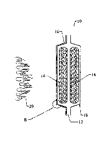
As shown in Fig. 1A, an embodiment of a thermal acoustic insulation system 10,
or "blanket", is depicted in cross-section, in which two insulating layers 14,
such as one
inch thick MICROLITE AA Premium NR fiberglass insulation (0.42 pcf)
(available
from Johns Manville International, Inc.), are disposed within a covering of an
exteriorly
facing fire barrier laminate 16, and an interiorly facing inboard cover film
18 (optionally,
a second fire barrier laminate). The insulating layers 14 may also or
alternatively
comprise polyimide foam insulation. The exteriorly facing laminate 16 and the
inboard
film 18 may be heat sealed with an adhesive 12 to partially or substantially
totally
envelop or encapsulate the fiberglass insulation layers. Flames 20, depicting
the FAA test
procedures, are shown proximate to the exteriorly facing fire barrier laminate
16.
A detail section of an embodiment of the fire barrier laminate 16, encircled
as B'
in Fig. lA is shown in an exploded cross-sectional view in Fig. 1B. The fire
barrier
laminate 16 is constructed by first applying an adhesive 104 to a first
polymeric flame
propagation resistant film 106, such as a polyetheretherketone film. The fire
barrier layer
102 is then coated onto the adhesive 104-coated first polymeric film 106.
Alternatively,
the adhesive 104 may be omitted, resulting in the fire barrier layer 102 being
coated
directly onto the first polymeric film 106. The fire barrier layer 102 may
comprise a
paste or slurry type material with an amount of water or other solvent being
present in the
fire barrier layer 102 as it is being coated onto the first polymeric film
106. In this
instance, the fire barrier layer 102 is allowed to dry before continued
processing.
Optionally, a water-repellant material may be incorporated in, coated onto or
saturated/impregnated into the fire barrier layer 102.
Separately, a scrim layer 108, such as a fiberglass or nylon scrim, is
laminated to a
second film 110, such as a polyetheretherketone film, using an adhesive 114.
An
adhesive 112 is also used to laminate the fire barrier layer 102-coated first
polymeric film
106 to the scrim layer 108. Alternatively, the scrim layer 108 may be adhered
to the fire
barrier layer 102 prior to laminating the scrim layer 108 to the second film
110.
12
CA 02854356 2014-05-01
WO 2013/074968 PCT/US2012/065591
Optionally, the assembled fire barrier laminate 16 includes an encapsulating
adhesive layer 116 adjacent to the first polymeric film 106 in order to
encapsulate the
insulation layers 14 between the fire barrier laminate 16 and the inboard film
18.
Additionally or alternatively, the fire barrier laminate 16 may utilize
mechanical fasteners
or tapes for encapsulating the insulating layers 14 between the fire barrier
laminate 16 and
the inboard film 18.
A detail section of another embodiment of the fire barrier laminate 16,
encircled
as B' in Fig. IA is shown in an exploded cross-sectional view in Fig. IC. The
fire barrier
laminate 16 is constructed by first applying an adhesive 204 to a first
polymeric flame
propagation resistant film 206, such as a ethylene chlorotrifluoroethylene
film. The fire
barrier layer 202 is then coated onto the adhesive 204-coated first polymeric
film 206.
Alternatively, the adhesive 204 may be omitted, resulting in the fire barrier
layer 202
being coated directly onto the first polymeric film 206. The fire barrier
layer 202 may
comprise a paste or slurry type material with an amount of water or other
solvent being
present in the fire barrier layer 202 as it is being coated onto the first
polymeric film 206.
In this instance, the fire barrier layer 202 is allowed to dry before
continued processing.
Optionally, a water-repellant material may be incorporated in, coated onto or
saturated/impregnated into the fire barrier layer 202.
A second film 210, such as a metalized polyetheretherketone film, is laminated
to
the fire barrier layer 202-coated first polymeric film 206 using an adhesive
212. The fire
barrier laminate 16 includes a scrim layer 208 laminated to the first
polymeric film 206
opposite the fire barrier layer 202 via an adhesive layer 216.
A detail section of a further embodiment of the fire barrier laminate 16,
encircled
as B' in Fig. IA is shown in an exploded cross-sectional view in Fig. 1D The
fire barrier
laminate 16 is constructed by first applying an adhesive 304 to a first
polymeric flame
propagation resistant film 306, such as a metalized polyetheretherketone film.
The fire
barrier layer 302 is then coated onto the adhesive 304-coated first polymeric
film 306.
Alternatively, the adhesive 304 may be omitted, resulting in the fire barrier
layer 302
being coated directly onto the first polymeric film 306. The fire barrier
layer 302 may
comprise a paste or slurry type material with an amount of water or other
solvent being
present in the fire barrier layer 302 as it is being coated onto the first
polymeric film 306.
13
CA 02854356 2014-05-01
WO 2013/074968 PCT/US2012/065591
In this instance, the fire barrier layer 302 is allowed to dry before
continued processing.
Optionally, a water-repellant material may be incorporated in, coated onto or
saturated/impregnated into the fire barrier layer 302.
Separately, a scrim layer 308, such as a fiberglass or nylon scrim, is
laminated to a
second film 310, such as a polyetheretherketone film. An adhesive 312 is also
used to
laminate the fire barrier layer 302-coated first polymeric film 306 to the
scrim layer 308.
Alternatively, the scrim layer 308 may be adhered to the fire barrier layer
302 prior to
laminating the scrim layer 308 to the second film 310.
The assembled fire barrier laminate 16 may include an encapsulating adhesive
layer 316 adjacent to the first polymeric film 306 in order to encapsulate the
insulation
layers 14 between the fire barrier laminate 16 and the inboard film 18. A
second scrim
layer 308a is optionally embedded in the adhesive layer 316.
A detail section of a further embodiment of the fire barrier laminate 16,
encircled
as B' in Fig. lA is shown in an exploded cross-sectional view in Fig. 1E. The
fire barrier
laminate 16 is constructed by first applying an adhesive 404 to a first
polymeric flame
propagation resistant film 406, such as a polyetheretherketone film. A second
scrim layer
408a is optionally laminated between the adhesive 404 and the first polymeric
film 406.
The fire barrier layer 402 is then coated onto the adhesive 404-coated first
polymeric film
406. Alternatively, the adhesive 404 may be omitted, resulting in the fire
barrier layer
402 being coated directly onto the first polymeric film 406. The fire barrier
layer 402
may comprise a paste or slurry type material with an amount of water or other
solvent
being present in the fire barrier layer 402 as it is being coated onto the
first polymeric
film 406. In this instance, the fire barrier layer 402 is allowed to dry
before continued
processing. Optionally, a water-repellant material may be incorporated in,
coated onto or
saturated/impregnated into the fire barrier layer 402.
A second film 410, such as a metalized polyetheretherketone film, is laminated
to
the fire barrier layer 402-coated first polymeric film 406 using an adhesive
412. The fire
barrier laminate 16 includes a scrim layer 408 laminated to the first
polymeric film 406
opposite the fire barrier layer 402 via an adhesive layer 416.
14
The following examples are set forth merely to further illustrate the subject
fire
barrier layer and fire barrier film laminate. The illustrative examples should
not be
construed as limiting the fire barrier layer and/or fire barrier laminate in
any manner.
TEST PROTOCOLS
The fire barrier film laminate-protected thermal/acoustic insulation blankets
described above were tested according to the protocols of 14 C.F.R.
25.856(a) and (b),
Appendix F, Parts VI and VII.
14 C.F.R. 25.856(a) and (b) provide in pertinent part:
Table 2
25.856 Thermal/Acoustic insulation materials.
(a) 'Thermal/acoustic insulation material installed in the fuselage must
meet the flame propagation test requirements of part VI of Appendix F to
this part, or other approved equivalent test requirements.
(b) For airplanes with a passenger capacity of 20 or greater,
thermal/acoustic insulation materials (including the means of fastening the
materials to the fuselage) installed in the lower half of the airplane
fuselage must meet the flame penetration resistance test requirements of
part VII of Appendix F to this part, or other approved equivalent test
requirements.
Appendix F Part VI provides, in pertinent part:
Table 3
Part VI -- Test Method To Determine the Flammability and Flame
Propagation Characteristics of Thermal/Acoustic Insulation Materials
Use this test method to evaluate the flammability and flame propagation
characteristics of thermal/acoustic insulation when exposed to both a
radiant heat source and a flame.
(a) Definitions.
CA 2854356 2019-04-24
CA 02854356 2014-05-01
WO 2013/074968
PCT/US2012/065591
"Flame propagation" means the furthest distance of the propagation of
visible flame towards the far end of the test specimen, measured from the
midpoint of the ignition source flame. Measure this distance after initially
applying the ignition source and before all flame on the test specimen is
extinguished. The measurement is not a determination of burn length
made after the test.
"Radiant heat source" means an electric or air propane panel.
"Thermal/acoustic insulation" means a material or system of materials
used to provide thermal and/or acoustic protection. Examples include
fiberglass or other batting material encapsulated by a film covering and
foams.
"Zero point" means the point of application of the pilot burner to the test
specimen.
(b) Test apparatus.
(4) Pilot Burner. The pilot burner used to ignite the specimen must be a
BernzomaticTM commercial propane venturi torch with an axially
symmetric burner tip and a propane supply tube with an orifice diameter
of 0.006 inches (0.15 mm). The length of the burner tube must be 2 7/8
inches (71 mm). The propane flow must be adjusted via gas pressure
through an in-line regulator to produce a blue inner cone length of 3/4 inch
(19 mm). A 3/4 inch (19 mm) guide (such as a thin strip of metal) may be
soldered to the top of the burner to aid in setting the flame height. The
overall flame length must be approximately 5 inches long (127 mm).
Provide a way to move the burner out of the ignition position so that the
flame is horizontal and at least 2 inches (50 mm) above the specimen
plane.
(5) Thermocouples. Install a 24 American Wire Gauge (AWG) Type K
(Chromel-Alumel) thermocouple in the test chamber for temperature
monitoring. Insert it into the chamber through a small hole drilled through
the back of the chamber. Place the thermocouple so that it extends 11
inches (279 mm) out from the back of the chamber wall, 11 1/2 inches
(292 mm) from the right side of the chamber wall, and is 2 inches (51 mm)
below the radiant panel. The use of other thermocouples is optional.
16
CA 02854356 2014-05-01
WO 2013/074968
PCT/US2012/065591
(6) Calorimeter. The calorimeter must be a one-inch cylindrical water-
cooled, total heat flux density, foil type Gardon Gage that has a range of 0
to 5 BTU/ft2-second (0 to 5.7 Watts/cm2).
(c) Test specimens.
(1) Specimen preparation. Prepare and test a minimum of three test
specimens. If an oriented film cover material is used, prepare and test both
the warp and fill directions.
(2) Construction. Test specimens must include all materials used in
construction of the insulation (including batting, film, scrim, tape etc.).
Cut a piece of core material such as foam or fiberglass, and cut a piece of
film cover material (if used) large enough to cover the core material. Heat
sealing is the preferred method of preparing fiberglass samples, since they
can be made without compressing the fiberglass ("box sample"). Cover
materials that are not heat sealable may be stapled, sewn, or taped as long
as the cover material is over-cut enough to be drawn down the sides
without compressing the core material. The fastening means should be as
continuous as possible along the length of the seams. The specimen
thickness must be of the same thickness as installed in the airplane.
(3) Specimen Dimensions. To facilitate proper placement of specimens in
the sliding platform housing, cut non-rigid core materials, such as
fiberglass, 12 1/2 inches (318mm) wide by 23 inches (584mm) long. Cut
rigid materials, such as foam, 111/2 1/4 inches (292 mm 6 mm) wide
by 23 inches (584mm) long in order to fit properly in the sliding platform
housing and provide a flat, exposed surface equal to the opening in the
housing.
(d) Specimen conditioning. Condition the test specimens at 70 5 F (210
2 C) and 55% 10% relative humidity, for a minimum of 24 hours prior
to testing.
(f) Test Procedure.
(1) Ignite the pilot burner. Ensure that it is at least 2 inches (51 mm) above
the top of the platform. The burner must not contact the specimen until the
test begins.
(2) Place the test specimen in the sliding platform holder. Ensure that the
test sample surface is level with the top of the platform. At "zero" point,
17
CA 02854356 2014-05-01
WO 2013/074968
PCT/US2012/065591
the specimen surface must be 7 1/2 inches +1/8 inch (191 mm +3) below
the radiant panel.
(3) Place the retaining/securing frame over the test specimen. It may be
necessary (due to compression) to adjust the sample (up or down) in order
to maintain the distance from the sample to the radiant panel (7 1/2 inches
+1/8 inch (191 mm+3) at "zero" position). With film/fiberglass
assemblies, it is critical to make a slit in the film cover to purge any air
inside. This allows the operator to maintain the proper test specimen
position (level with the top of the platform) and to allow ventilation of
gases during testing. A longitudinal slit, approximately 2 inches (51mm)
in length, must be centered 3 inches +1/2 inch (76mm +13 mm) from the
left flange of the securing frame. A utility knife is acceptable for slitting
the film cover.
(4) Immediately push the sliding platform into the chamber and close the
bottom door.
(5) Bring the pilot burner flame into contact with the center of the
specimen at the "zero" point and simultaneously start the timer. The pilot
burner must be at a 270 angle with the sample and be approximately 1/2
inch (12 mm) above the sample. A stop ... allows the operator to position
the burner correctly each time.
(6) Leave the burner in position for 15 seconds and then remove to a
position at least 2 inches (51 mm) above the specimen.
(g) Report.
(1) Identify and describe the test specimen.
(2) Report any shrinkage or melting of the test specimen.
(3) Report the flame propagation distance. If this distance is less than 2
inches, report this as a pass (no measurement required).
(4) Report the after-flame time.
(h) Requirements.
(1) There must be no flame propagation beyond 2 inches (51 mm) to the
left of the centerline of the pilot flame application.
(2) The flame time after removal of the pilot burner may not exceed 3
seconds on any specimen.
18
CA 02854356 2014-05-01
WO 2013/074968 PCT/US2012/065591
Appendix F Part VII provides, in pertinent part:
Table 4
Part VII -- Test Method To Determine the Burnthrough Resistance of
Thermal/Acoustic
Insulation Materials
Use the following test method to evaluate the burnthrough resistance
characteristics of aircraft thermal/acoustic insulation materials when exposed
to a
high intensity open flame.
(a) Definitions.
Burnthrough time means the time, in seconds, for the burner flame to
penetrate the test specimen, and/or the time required for the heat flux to
reach 2.0 Btulft2sec (2.27 W/cm2) on the inboard side, at a distance of 12
inches (30.5 cm) from the front surface of the insulation blanket test
frame, whichever is sooner. The burnthrough time is measured at the
inboard side of each of the insulation blanket specimens.
Insulation blanket specimen means one of two specimens positioned in
either side of the test rig, at an angle of 30 with respect to vertical.
Specimen set means two insulation blanket specimens. Both specimens
must represent the same production insulation blanket construction and
materials, proportioned to correspond to the specimen size.
(b) Apparatus.
(3) Calibration rig and equipment.
(i) Construct individual calibration rigs to incorporate a calorimeter and
thermocouple rake for the measurement of heat flux and temperature.
Position the calibration rigs to allow movement of the burner from the test
rig position to either the heat flux or temperature position with minimal
difficulty.
(ii) Calorimeter. The calorimeter must be a total heat flux, foil type
Gardon Gage of an appropriate range such as 0-20 Btu/ft2-sec (0-22.7
W/cm2), accurate to +3% of the indicated reading. The heat flux
calibration method must be in accordance with paragraph VI(b)(7) of this
appendix.
(iv) Thermocouples. Provide seven 1/8-inch (3.2 mm) ceramic packed,
metal sheathed, type K (Chromel-alumel), grounded junction
19
CA 02854356 2014-05-01
WO 2013/074968
PCT/US2012/065591
thermocouples with a nominal 24 American Wire Gauge (AWG) size
conductor for calibration. Attach the thermocouples to a steel angle
bracket to form a thermocouple rake for placement in the calibration rig
during burner calibration.
(5) Backface calorimeters. Mount two total heat flux Gardon type
calorimeters behind the insulation test specimens on the back side (cold)
area of the test specimen mounting frame. Position the calorimeters along
the same plane as the burner cone centerline, at a distance of 4 inches (102
mm) from the vertical centerline of the test frame.
(i) The calorimeters must be a total heat flux, foil type Gardon Gage of an
appropriate range such as 0-5 Btu/ft2-sec (0-5.7 VV/cm2), accurate to +3%
of the indicated reading. The heat flux calibration method must comply
with paragraph VI(b)(7) of this appendix.
(6) Instrumentation. Provide a recording potentiometer or other suitable
calibrated instrument with an appropriate range to measure and record the
outputs of the calorimeter and the thermocouples.
(7) Timing device. Provide a stopwatch or other device, accurate to 1%,
to measure the time of application of the burner flame and burnthrough
time.
(c) Test Specimens.
(1) Specimen preparation. Prepare a minimum of three specimen sets of
the same construction and configuration for testing.
(2) Insulation blanket test specimen.
(i) For batt-type materials such as fiberglass, the constructed, finished
blanket specimen assemblies must be 32 inches wide by 36 inches long
(81.3 by 91.4 cm), exclusive of heat sealed film edges.
(3) Construction. Make each of the specimens tested using the principal
components (i.e., insulation, fire barrier material if used, and moisture
barrier film) and assembly processes (representative seams and closures).
(i) Fire barrier material. If the insulation blanket is constructed with a
fire
barrier material, place the fire barrier material in a manner reflective of
the
installed arrangement For example, if the material will be placed on the
outboard side of the insulation material, inside the moisture film, place it
the same way in the test specimen.
CA 02854356 2014-05-01
WO 2013/074968
PCT/US2012/065591
(v) Conditioning. Condition the specimens at 700 +5 F (210 +2 C) and
55% +10% relative humidity for a minimum of 24 hours prior to testing.
(f) Test procedure.
(1) Secure the two insulation blanket test specimens to the test frame. The
insulation blankets should be attached to the test rig center vertical former
using four spring clamps .... (according to the criteria of paragraph (c)(4)
or (c)(4)(i) of this part of this appendix).
(2) Ensure that the vertical plane of the burner cone is at a distance of 4
+0.125 inch (102 +3 mm) from the outer surface of the horizontal stringers
of the test specimen frame, and that the burner and test frame are both
situated at a 30 angle with respect to vertical.
(3) When ready to begin the test, direct the burner away from the test
position to the warm-up position so that the flame will not impinge on the
specimens prematurely. Turn on and light the burner and allow it to
stabilize for 2 minutes.
(4) To begin the test, rotate the burner into the test position and
simultaneously start the timing device.
(5) Expose the test specimens to the burner flame for 4 minutes and then
turn off the burner. Immediately rotate the burner out of the test position.
(6) Determine (where applicable) the bumthrough time, or the point at
which the heat flux exceeds 2.0 Btulft2-sec (2.27 W/cm2).
(g) Report.
(1) Identify and describe the specimen being tested.
(2) Report the number of insulation blanket specimens tested.
(3) Report the bumthrough time (if any), and the maximum heat flux on
the back face of the insulation blanket test specimen, and the time at which
the maximum occurred.
(h) Requirements.
(1) Each of the two insulation blanket test specimens must not allow fire
or flame penetration in less than 4 minutes.
(2) Each of the two insulation blanket test specimens must not allow more
than 2.0 Btulft2-sec (2.27 W/cm2) on the cold side of the insulation
specimens at a point 12 inches (30.5 cm) from the face of the test rig.
21
CA 02854356 2014-05-01
WO 2013/074968 PCT/US2012/065591
In a first embodiment, a subject fire barrier laminate may comprise: at least
one
fire barrier layer directly or indirectly coated onto at least one first
polymeric flame
propagation resistant film layer; at least one second film layer proximate to
the fire barrier
layer opposite the first polymeric flame propagation resistant film layer; at
least one scrim
layer disposed: (i) between the fire barrier layer and the first polymeric
flame propagation
resistant film layer; and/or (ii) between the fire barrier layer and the
second film layer;
and/or (iii) proximate to the first polymeric flame propagation resistant film
layer
opposite the fire barrier layer; and/or (iv) proximate to the second film
layer opposite the
fire barrier layer; optionally, a water-repellant material incorporated into
and/or applied to
the fire barrier layer; optionally at least one adhesive layer adhering the
fire barrier layer
to the first polymeric flame propagation resistant film layer; and optionally
at least one
adhesive layer adhering the scrim layer to at least one of the fire barrier
layer, the first
polymeric flame propagation resistant film layer, or the second film layer;
wherein the
fire barrier layer comprises inorganic fibers, at least one inorganic platelet
material,
optionally at least one organic binder and/or inorganic binder, and optionally
at least one
functional filler.
The fire barrier laminate of the first embodiment may further include that the
inorganic platelet material comprises at least one of vermiculite, mica, clay
or talc. The
vermiculite may be exfoliated and optionally defoliated. The clay may comprise
at least
one of ball clay, bentonite, smectite, hectorite, kaolinite, montmorillonite,
saponite,
sepiolite or sauconite.
The fire barrier laminate of either or both of the first or subsequent
embodiments
may further include that the organic binder comprises at least one of acrylic
latex,
(meth)acrylic latex, phenolic resins, copolymers of styrene and butadiene,
vinylpyridine,
acryl on i trile, copolymers of acryl on itrile and styrene, vinyl chloride,
polyurethane,
copolymers of vinyl acetate and ethylene, polyamides, silicones, unsaturated
polyesters,
epoxy resins or polyvinyl esters.
The fire barrier laminate of any of the first or subsequent embodiments may
further include that the inorganic binder comprises at least one of colloidal
alumina,
colloidal silica or colloidal zirconia.
22
CA 02854356 2014-05-01
WO 2013/074968 PCT/US2012/065591
The fire barrier laminate of any of the first or subsequent embodiments may
further include that the fire barrier layer comprises from about 2% to about
50% by
weight of the inorganic fibers, from about 20% to about 98% by weight of the
inorganic
platelet material, from 0% to about 40% by weight of the organic binder and/or
inorganic
binder, and from 0% to about 50% of the functional filler.
The fire barrier laminate of any of the first or subsequent embodiments may
further include that the fire barrier layer comprises from about 2% to about
40% of the
inorganic fibers, from about 60% to about 98% by weight of the inorganic
platelet
material, from 0% to about 20% by weight of the organic binder and/or
inorganic binder,
and from 0% to about 20% of the functional filler.
The fire barrier laminate of any of the first or subsequent embodiments may
further include that the fire barrier layer comprises from about 2% to about
30% by
weight of the inorganic fibers, from about 20% to about 98% by weight of the
inorganic
platelet material, from 0% to about 40% by weight of the organic binder and/or
inorganic
binder, and from 0% to about 50% of the functional filler.
The fire barrier laminate of any of the first or subsequent embodiments may
further include that the fire barrier layer comprises from about 2% to about
20% by
weight of the inorganic fibers, from about 20% to about 98% by weight of the
inorganic
platelet material, from 0% to about 40% by weight of the organic binder and/or
inorganic
binder, and from 0% to about 50% of the functional filler.
The fire barrier laminate of any of the first or subsequent embodiments may
further include that the fire barrier layer comprises from about 2% to about
10% by
weight of the inorganic fibers, from about 20% to about 98% by weight of the
inorganic
platelet material, from 0% to about 40% by weight of the organic binder and/or
inorganic
binder, and from 0% to about 50% of the functional filler.
The fire barrier laminate of any of the first or subsequent embodiments may
further include that either or both of the first polymeric flame propagation
resistant film
layer or the second film layer comprises at least one of polyesters,
polyimides,
polyetherketones, polyetheretherketones, polyvinylfluorides,
polyamides,
23
CA 02854356 2014-05-01
WO 2013/074968 PCT/US2012/065591
polytetrafluoroethylenes, polyaryl sulfones, polyester amides, polyester
imides,
polyethersulfones, polyphenylene sulfides, or combinations thereof
The fire barrier laminate of any of the first or subsequent embodiments may
further include that the at least one scrim layer comprises at least one of
fiberglass, nylon,
polyester, aramid, or high or ultra-high molecular weight polyethylene.
The fire barrier laminate of any of the first or subsequent embodiments may
further include that either or both of the first polymeric flame propagation
resistant film
layer and the second film layer are metalized. Either or both of the first
polymeric flame
propagation resistant film layer or the second film layer have an opaque, low-
gloss
polymer coating, optionally including a fire retardant additive.
The fire barrier laminate of any of the first or subsequent embodiments may
have
a basis weight of less than about 120 gsm.
In a second embodiment, a subject thermal acoustic insulation system may
comprise a plurality of insulating layers disposed within a covering of an
exteriorly facing
fire barrier laminate as in any of the first or subsequent embodiments, and an
interiorly
facing inboard cover film.
The thermal acoustic insulation system of the second embodiment may further
include that the interiorly facing cover film also comprises the fire barrier
laminate of the
first or subsequent embodiments.
The thermal acoustic insulation system of either or both of the second or
subsequent embodiments may further include that the exteriorly facing fire
barrier
laminate and the interiorly facing inboard cover film are sealed with an
adhesive to
partially or substantially totally envelop or encapsulate the plurality of
insulating layers.
The thermal acoustic insulation system of any of the second or subsequent
embodiments may further include that the insulating layers comprise fiberglass
insulation
and/or polyimide foam insulation.
24
CA 02854356 2014-05-01
WO 2013/074968 PCT/US2012/065591
The thermal acoustic insulation system of any of the second or subsequent
embodiments may be capable of passing the flame propagation and burn-through
resistance test protocols of 14 C.F.R. 25.856(a) and (b), Appendix F, Parts
VI and VII.
In a third embodiment, a subject method of making a fire barrier laminate may
comprise: directly or indirectly coating at least one fire barrier layer onto
a first polymeric
flame propagation resistant film layer; laminating the fire barrier layer with
at least one
second film layer, wherein the second film layer is proximate to the fire
barrier layer; and
laminating at least one scrim layer within the fire barrier laminate, wherein
the at least
one scrim layer is disposed: (i) between the fire barrier layer and the first
polymeric flame
propagation resistant film layer; and/or (ii) between the fire barrier layer
and the second
film layer; and/or (iii) proximate to the first polymeric flame propagation
resistant film
layer opposite the fire barrier layer; and/or (iv) proximate to the second
film layer
opposite the fire barrier layer; wherein the fire barrier layer comprises
inorganic fibers, at
least one inorganic platelet material, optionally at least one organic binder
and/or
inorganic binder, and optionally at least one functional filler; and wherein
the fire barrier
layer optionally contains a water repellant material, and/or the method
further comprises
optionally coating and/or saturating the fire barrier layer with a water
repellant material.
The method of the third embodiment may further include that the inorganic
platelet material comprises at least one of vermiculite, mica, clay or talc.
The vermiculite
may be exfoliated and optionally defoliated.
The method of either or both of the third or subsequent embodiments may
further
include that the organic binder comprises at least one of acrylic latex,
(meth)acrylic latex,
phenolic resins, copolymers of styrene and butadiene, vinylpyridine,
acrylonitrile,
copolymers of acrylonitrile and styrene, vinyl chloride, polyurethane,
copolymers of vinyl
acetate and ethylene, polyamides, silicones, unsaturated polyesters, epoxy
resins or
polyvinyl esters.
The method of any of the third or subsequent embodiments may further include
that the inorganic binder comprises at least one of colloidal alumina,
colloidal silica or
colloidal zirconia.
CA 02854356 2014-05-01
WO 2013/074968 PCT/US2012/065591
The method of any of the third or subsequent embodiments may further include
that the fire barrier layer comprises from about 2% to about 50% by weight of
the
inorganic fibers, from about 20% to about 98% by weight of the inorganic
platelet
material, from 0% to about 40% by weight of the organic binder and/or
inorganic binder,
and from 0% to about 50% of the functional filler.
The method of any of the third or subsequent embodiments may further include
that the fire barrier layer comprises from about 2% to about 40% by weight of
the
inorganic fibers, from about 20% to about 98% by weight of the inorganic
platelet
material, from 0% to about 40% by weight of the organic binder and/or
inorganic binder,
and from 0% to about 50% of the functional filler.
The method of any of the third or subsequent embodiments may further include
that the fire barrier layer comprises from about 2% to about 30% by weight of
the
inorganic fibers, from about 20% to about 98% by weight of the inorganic
platelet
material, from 0% to about 40% by weight of the organic binder and/or
inorganic binder,
and from 0% to about 50% of the functional filler.
The method of any of the third or subsequent embodiments may further include
that the fire barrier layer comprises from about 2% to about 20% by weight of
the
inorganic fibers, from about 20% to about 98% by weight of the inorganic
platelet
material, from 0% to about 40% by weight of the organic binder and/or
inorganic binder,
and from 0% to about 50% of the functional filler.
The method of any of the third or subsequent embodiments may further include
that the fire barrier layer comprises from about 2% to about 10% by weight of
the
inorganic fibers, from about 20% to about 98% by weight of the inorganic
platelet
material, from 0% to about 40% by weight of the organic binder and/or
inorganic binder,
and from 0% to about 50% of the functional filler.
The method of any of the third or subsequent embodiments may further include
that either or both of the first polymeric flame propagation resistant film
layer or the
second film layer comprises at least one of polyesters, polyimides,
polyetherketones,
polyetheretherketones, polyvinylfluorides, polyamides,
polytetrafluoroethylenes, polyaryl
26
CA 02854356 2014-05-01
WO 2013/074968 PCT/US2012/065591
sulfones, polyester amides, polyester imides, polyethersulfones, polyphenylene
sulfides,
or combinations thereof.
The method of any of the third or subsequent embodiments may further include
that the at least one scrim layer comprises at least one of fiberglass, nylon,
polyester,
aramid, or high or ultra-high molecular weight polyethylene.
The method of any of the third or subsequent embodiments may further include
that either or both of the first polymeric flame propagation resistant film
layer or the
second film layer are metalized. Either or both of the first polymeric flame
propagation
resistant film layer or the second film layer may be coated with an opaque,
low-gloss
polymer, optionally including a fire retardant additive.
It will be understood that the embodiments described herein are merely
exemplary, and that one skilled in the art may make variations and
modifications without
departing from the spirit and scope of the invention. All such variations and
modifications are intended to be included within the scope of the invention as
described
hereinabove. Further, all embodiments disclosed are not necessarily in the
alternative, as
various embodiments of the invention may be combined to provide the desired
result.
27