Note : Les descriptions sont présentées dans la langue officielle dans laquelle elles ont été soumises.
CA 02854521 2016-04-05
DUAL ELEVATOR LARGE BOTTLE VENDING APPARATUS
CROSS-REFERENCE TO RELATED APPLICATIONS
[001] This application claims priority to U.S. Provisional Application
Serial
Nos. 61/654,585, filed June 1,2012; 61/568,661, filed December 9, 2011;
61/560,835, filed November 17, 2011; 61,546,091, filed October 12, 2011 and
U.S.
Regular Utility Application Serial No. 13/407,452, filed February 28, 2012.
FIELD OF THE DISCLOSURE:
[002] The disclosure relates generally to a vending apparatus for vending
consumable goods and for receiving emptied reusable containers for the
consumable goods. More specifically, the disclosure relates to an apparatus
for
vending large volume water bottles and receiving emptied re-sanitizable and
reusable bottles.
BACKGROUND OF THE DISCLOSURE:
[003] Potable, portable water has become an increasingly sought-after and
common-place commodity by modern day consumers. Whether natural spring
water, or purified and/or re-mineralized drinking water, to address varying
consumer
demands for convenience and availability, water vendors have developed a
number
of bottle sizes and approaches to dispense and to deliver water. One such
approach
described more fully below uses established food stores, e.g., supermarkets,
wholesale and convenience stores, as well as other types of retail
establishments,
within which bottled water in varying sizes is normally offered on store
shelves. A
second approach is to offer larger 3, 4 and 5 gallon bottles, often stacked
independently of the market's shelves due to their considerable weight, and
later to
normally be used with water coolers for dispensing.
[004] For companies involved in the home and office water delivery
business, competition with respect to price, service, contract terms,
availability of
product, consistency of product, permitting in and out of state, delivery
expenses
including the acquisition of, or lease of, government approved trucks, fuel
costs, tolls,
taxes, maintenance and repair, labor and labor related benefits all add
considerably
to the cost of the delivered water. Additional costs such as a sales force,
LSS-BVA/PCT-CDA
CA 02854521 2016-04-05
bookkeeping department, plant inventory, delivered inventory, truck-loaded
inventory
and FIFO handling of product inventory, further add to the cost. Regional
weather
and security-related issues can affect deliveries to homes, offices and
apartment
buildings.
[005] An additional problem is the use of rented water coolers. Companies
providing on-site delivery services that rent coolers to their customers have
to deal
with repair and maintenance, cleaning, billing and collection of rental fees
and
access to gated communities and high-rise apartments.
[006] A yet further set of issues with respect to the home/office delivery
business concerns state permitting practices and procedures. States vary
considerably in their permitting requirements such that one company may decide
against doing business in certain states to avoid disparate permitting
requirements.
[007] Distribution of particular brands of water for home/office delivery
may
be further restricted by geographical considerations, such as distance from a
bottling
facility. Many homes and businesses may be outside the feasible mileage radius
of
the bottling plant to warrant delivery at a competitive or acceptable price.
The end
result is the delivery of bottles and coolers along with all the related costs
creates a
fractionalized cost model that requires high volume to achieve low margins.
[008] Similar problems surface with the distribution of 3 and 5 gallon
bottles
through supermarket and wholesale club stores. "Centralizing" distribution
does
centralize costs and simplify bottle delivery and empty bottle pickup. It also
reduces
or eliminates many of the other problems associated with home/office delivery.
Problems such as billing and collection, however, still remain, even though on
a
centralized, consolidated manner wherein the bottler invoices the supermarket
and
wholesale stores rather than invoice individual home and/or office customers.
One
solution to the invoicing issue is to rely on the retailer to electronically
transfer funds
directly and automatically. This has become increasingly popular with the
advent of
e-commerce.
[009] In this particular model of distribution, the customers serve
themselves
and prepay for the bottled water products, and often prepay for the bottles as
well, at
a central location instead of being invoiced separately at dispersed locations
for the
2
LSS-BVA/PCT-CDA
CA 02854521 2016-04-05
delivered bottle water purchase and/or cooler rental. One of the drawbacks of
this
model is retailer control over hours of operation and location that limits
customer
access to water bottles.
[010] As an added difficulty/inconvenience, the customer must carry/handle
the product to a certain extent in order to get the 3, 4 or 5 gallon bottle to
their
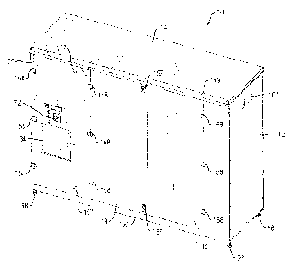
vehicle from inside the store. Such purchases are often performed
simultaneously
with shopping for other items inside the store, (depending upon whether it's a
grocer
or retailer--this can be a significant limitation), that only adds to the
inconvenience.
And often times, this will result in a separate trip back and forth to the
vehicle and
back and forth to customer service to return empties, and in some cases, to
receive
a voucher, to stand in line in order to present to a cashier as a credit
against the
purchase of a new bottled water product and then again out to the vehicle (or
continue to shop inside the store before travelling back to the vehicle). This
can
have the unfortunate effect of limiting sales brought about by the
inconvenience
inherent when large water bottles are purchased.
[011] This model of distribution thus has significant temporal and
convenience limitations as it relies entirely on the individual store hours
and on the
location(s) of the stores. A further inconvenience and limitation is based
upon the
location(s) inside stores where bottles are returned and where bottles are
purchased
and retrieved. Added to this is the common practice of using vouchers to
confirm
bottle returns for a return-bottle credit, which, if lost, or the receipt
printer is out of
order, cannot be used to obtain a credit against a subsequent purchase of a
filled
bottle.
[012] A substantial reason why water bottles are sold in stores is due to
the
effect of climate and weather on water. If left exposed to the elements¨even
in
sealed containers¨water can freeze and/or overheat. In the alternative, even
if the
bottled water were to be stacked outside the store on the sidewalk (so to
speak) for
purchase, it would still have to be brought back into the store at closing to
reduce the
risk of theft and to prevent freezing in colder climates. By way of example,
there can
be as many as 75-100 bottles stacked on the shelves of wholesale clubs. If not
left
inside the store, but displayed for sale outside, the bottles would need to be
taken in
each and every night absent some form of security measure such as a security
fence
3
LSS-BVA/PCT-CDA
CA 02854521 2016-04-05
with a locked door/gate. It should come as no surprise that water bottles sold
by
wholesale clubs are more likely to sell than bottles from store racks/shelves
inside
the club facilities.
[013] Not only does this model create extra effort and handling for the
customer, just as importantly, it places a constant burden on the retailer as
it can
involve the ongoing and tedious tasks of price-labeling, of handling the piles
of
empties and of planning the use of valuable floor/shelf space in designated
"water
aisles" such as those found in a supermarket or a Wal-Mart store. The same
burden
is experienced when the bottles are placed on separate shelving or pallets in
retail
stores such as Home Depot, or Lowe's, or in food clubs such as B.J.'s
Wholesale
Club, Sam's Club, Costco, etc. These problems are exacerbated by the fact that
these self-serve products weigh about 44.5 lbs. per five gallon bottle and
about 25.5
lbs. per 3 gallon bottle. This creates significant handling logistics for both
the
consumer and the store. For example, a 3 gallon bottle typically takes up an
8"D ¨
10-1/2" D x 13"H space and an 11"D x 20"H space for a 5 gallon bottle. Sales
of,
and even profits derived from, this product can sometimes be negated by the
extra
handling and "shelf-space" required, and the available interior floor space
and
location available.
[014] Several other problems involving this distribution model are not
readily
apparent. For example, in the case of a grocery store, the customer must carry
the
45 lb., 32 lb., or 25 lb. bottles around the store in a grocery cart, wait in
line for a
check-out clerk and then bring the bottle out to his or her vehicle, sometimes
in
inclement weather conditions and across a parking lot, to their parking space
location that could be several hundred feet or yards away.
[015] This scenario is equally relevant to wholesale and retail store
locations
and may be worse because the customer must park their car; bring any empties
to
the "customer service area" to redeem their deposit(s) and get a receipt; go
to the
cashier (wait in another line); pay for a new bottle(s) of water; go to the
location
where the 3's and 5's are kept; pick up the purchased bottles; place them in a
basket
carrier and then wheel them out to their vehicle, much the same as in the
supermarket model. This is not the most customer friendly or convenient
delivery
model and again can stifle sales because many, if not most, shoppers at
4
LSS-BVA/PCT-CDA
CA 02854521 2016-04-05
supermarkets are consumers doing their weekly shopping. In this scenario,
buying
drinking water in large quantities is not necessarily a "destination," or
"convenient
purchase."
[016] In an improved form of distribution, 3, 4 and 5 gallon bottled water
can
be distributed during and outside normal business hours in a vending machine
model
designed to handle either the 3, 4 or 5 gallon sizes of bottled water and
their similarly
sized empty returns. This is accomplished by using a single apparatus, located
outside a retailer's store on a sidewalk, "end-cap", or some other similar,
customer-
friendly location where customers can drive up, buy and return their bottles
(24/7)
and leave. Alternatively, the customers can shop first if they choose, and
then
purchase their water on the way out of the store or simply come to the store
location
on their own schedule without having to interact with store personnel or be
concerned with store hours.
[017] In this novel distribution system, customers aren't reliant on
retailers'
hours of operation; both the bottle return and the purchase of the product are
in the
same apparatus; and retailers can offer guaranteed FDA and Board of Health
approved products "packaged" and not delivered "bulk." With use of Applicants'
novel apparatus, customers don't have to bring their own "clean and sanitary"
containers. The apparatus provides a cashless transaction that should reduce,
if not
eliminate theft because the apparatus is maintained in a closed condition 24/7
except during lawful purchase events. The apparatus further provides a
convenient
method of payment for the consumer because one of three or four methods of
payment may be offered. If cash is preferable, the system can accept a prepaid
water card, which can be purchased from the retailer associated with the
apparatus.
This method of payment is also compatible with retailers' cross-promotion
activities
such as discount programs where the customer can receive discounts off their
purchase with the use of apparatus-recognized, retailer-approved coupons
and/or
retailer "advantage" cards, or even the use of RFID payment methods, or 2-D
barcode for downloading coupons using new smartphone technologies.
[018] The vending apparatus is configured to include lighting adequate to
impart improved nighttime safety and appearance as well as improved customer-
friendly operating features. As an example, the entire front of the machine
and
L5S-BVA/PCT-CDA
CA 02854521 2016-04-05
interior portion of the bottle well are illuminated with LED, energy saving
lights. With
applicants' novel apparatus, inventory re-supply can be maintained on an "on
demand" basis as the apparatus includes wireless communication with the
bottler
and/or dispatch control center to report when the vending apparatus is low on
inventory, or needs service. The apparatus software is further configured to
allow
manual input of inventory when loading the full bottles thereby creating an
"Input"
and "Output Sales" Inventory control. A "return bottle" well/window can, if
need be,
incorporate a vendor controlled reader for RFID or bar codes secured to the
bottles
and incorporating a Unique Identification Number (U ID) acceptable only to
that
bottler's product bottles for the amount paid when first purchased. The
machine and
its individual major parts will be "serialized" using unique identification
technology as
disclosed in U.S. Patent Nos. RE 40,659 and RE 40,692
[019] With the use of Applicants' novel apparatus, many unnecessary and
unwanted business expenses and inconveniences are now eliminated as further
explained in this disclosure. The apparatus may also include clear,
multilingual
signage and voice instructions to assist customers with their purchases unlike
some
other models of distribution. The need for bookkeeping is essentially
eliminated due
to the apparatus' wireless, gateway and other automated features for all
parties
concerned. The size and shape of the vendor machine is expandable or
contractible
with modular features that allow for customization based upon the location,
and re-fill
delivery costs.
[020] There should be no building permits or other special permits/license
fees required unlike some other types of vending and distribution apparatuses
as
Applicants' vending apparatus should meet all NAMA, ADA and U/L requirements.
Although there are hundreds of various models and types of vending machines,
almost all of those machines and kiosks sell "packaged/bottled" water or soft
drinks
and are "small pack" sizes, less than 3 gallon, and do not address the
problems
associated with selling larger 3 and 5 gallon size bottles.
[021] Many currently available water vending machines are "unpackaged"
bulk water vending machines that require the customer to bring their own
"clean,
sanitary containers". These type machines are heavily regulated on an
individual
location basis and require, in many cases, both local and state permits and
licenses
6
LSS-BVA/PCT-CDA
CA 02854521 2016-04-05
from boards of health, plumbing, building and wiring inspectors as well as
local water
quality agencies such as the California Department of Health; the Rhode Island
Board of Health; the Massachusetts Department of Environmental Protection
(DEP);
the New York Department of Health; the Massachusetts Board of Health; the
Licensing Board of Certified Operators. These requirements can vary greatly
from
state to state. The disclosed vending apparatus eliminates these requirements
because all necessary permitting issues are already addressed before the
product is
loaded into a truck to deliver to the vending apparatuses at their retail
location(s).
[022] With respect to return bottles, in two currently used self-service
vending systems, the "Return Bottle" area is located generally in a customer
service
area located as one enters the retail store where the "return" is either put
in a
designated "Return Bottle Area" (loose and unconstrained) or in a "Return
Bottle"
enclosed compartment that accepts all bottles from all vendors and prints a
"refund"
slip to be cashed in when purchasing a new filled bottle at a location
elsewhere in
the store. It falls to the customer to push a grocery cart with their bottled
water--
bottles which can weigh as much as 45 lbs. per 5 gallon bottle and more,
depending
on the number of bottles purchased and the style of bottle used--out to their
vehicle
located some distance from the store exit. The disclosed vending apparatus
eliminates these inconveniences and problems almost entirely.
[023] What is needed is an apparatus that accommodates large 3, 4 and/or 5
gallon bottles and allows for the return of emptied bottles and the purchase
of filled
bottles from the same apparatus. What is also needed is an apparatus that can
execute a cashless retail sales transaction without the need for the presence
of a
merchant during normal business hours. These and other objects of the
disclosure
will become apparent from a reading of the following summary and detailed
description of the disclosure as well as a review of the appended drawings.
SUMMARY OF THE DISCLOSURE:
[024] Unless specified, as used herein, large-volume water bottles shall
mean reusable bottles holding one or more gallons of fluid. Also as used
herein,
"water bottle" defines bottles containing water, or fluids other than water.
In one
aspect of the disclosure, a combination vending/return apparatus includes
track
assemblies with preset slopes configured to receive filled water bottles for
vending
7
LSS-BVA/PCT-CDA
CA 02854521 2016-04-05
and empty water bottle returns. The track assemblies are positioned adjacent
to an
elevator shaft that includes an elevator apparatus to move empty bottles to,
and filled
bottles from, the track assemblies.
[025] A vending door with a central processor controlled lock system is
positioned in a front wall of the vending apparatus at a height sufficient to
meet the
requirements of the Americans with Disabilities Act. A shelf can be further
included
in proximity to the door to enhance the convenience of purchasing multiple
bottles.
A credit/debit/prepaid card acceptor connected either by Ethernet, landline or
wireless connection using a credible wireless provider, e.g., Verizon or AT&T
,
provides a means for customers to make purchases and receive credits for
returned
bottles via an atypical credit card gateway, e.g., USA Technologies, etc. A
completed electronic purchase transaction unlocks the vending door to permit
the
return of empty bottles and the retrieval of filled bottles. The system
includes access
to 24/7 service to accommodate any issues resulting from the purchase/return
event.
[026] In one aspect of the disclosure, the apparatus can include a double
bottle retention gate subassembly comprising two retention gates. A first
retention
gate retains a lead-most filled bottle on a bottom track assembly. A second
retention
gate retains the remainder of the filled bottles on the combined track
assemblies.
The first retention gate is released to permit lead-most bottle migration onto
an
adjacent elevator. Once the first retention gate is returned to a bottle
retention
position, the second retention gate is opened to allow the previously second
lead-
most bottle to roll into the lead-most position behind the first retention
gate. The
spatial separation of the gates allows only one bottle to move to the lead-
most
position between the gates. The remaining bottles roll forward approximately
one
bottle width and remain registered against one another. Once the new lead-most
bottle is registered against the first retention gate, and the remaining
bottles are
registered against one another including the new lead-most bottle, the second
retention gate is lowered into the bottle retention position to arrest forward
movement
of the now second lead-most bottle.
[027] In another aspect of the disclosure, a vending/return apparatus with
a
double elevator system allows the return of empty bottles and the purchase of
filled
bottles from the same vending machine access door. In a pre-transaction stage,
the
8
LSS-BVA/PCT-CDA
CA 02854521 2016-04-05
double elevator is positioned to align an upper return elevator with the
access door.
A lower vend elevator is positioned to permit a filled bottle to roll onto the
elevator
from a lower-most track assembly. A filled bottle may be resident on the lower
vend
elevator prior to the initiation of a vend/return transaction. During a
vend/return
transaction, a customer can initiate a transaction by making the appropriate
selections on a human-interface control panel. If a return is being made, the
customer will be able to open the access door and place an empty bottle on the
return elevator. After bottle verification of the 3, 4 and/or 5 gallon
bottles, depending
on the type of bottles being vended, the double elevator is raised to position
the vend
elevator in alignment with the access door and the return elevator in a
position to
transfer the resident empty bottle to one of the track assemblies.
[028] In a further aspect of the disclosure, the double elevator
configuration
may be configured to have multiple stops. In one embodiment, the return
elevator is
not positioned to permit transfer of a resident empty bottle when the lower
vend
elevator is positioned in alignment with the apparatus door. Once a purchased
bottle
is retrieved, the elevator is raised to align the upper return elevator with a
top track
assembly. As the elevator approaches the top track assembly, an extended,
spring-
supported segment of an articulated elevator bottle cradle assembly engages a
leading edge of the top track assembly to arrest motion of the segment while
the
remainder of the cradle continues upwardly. This causes a side edge of the
segment to cease elevating while the remainder of the segment and the elevator
proceed in an upwardly direction. This causes the support springs to compress
and
the segment to rotate downwardly from its hinge anchor to form a ramp sloping
downwardly toward the top track assembly. The resident empty bottle rolls off
the
elevator and onto the track assembly via gravity assist. Air operated,
hydraulic
and/or electric actuators are provided to move the double elevator among the
various functional positions. As the elevator moves downward to its next
position, the
spring loaded segment returns to its original orientation ready to accept the
next
empty bottle.
[029] In a still further aspect of the disclosure, the vending door may be
configured as a hinged door with a processor-controlled door lock, or as a
sliding
door opened and closed with a processor-controlled linear actuator, belt
driven
activator and the like. The sliding door is secured in a door slot formed in a
door
9
ISS-BVA/PCT-CDA
CA 02854521 2016-04-05
frame and in an apparatus wall. The door configuration permits movement of the
door to be controlled by the central processor to eliminate any manual
customer
control over the door function. These and other aspects and objects of the
disclosure will become apparent from a review of the appended drawings and the
detailed description below.
[029a] In a further aspect of the disclosure, a combination bottle
vending/return apparatus comprises an enclosure with at least one access door
or
panel. At least two stacked counter-sloped track assemblies are secured in the
enclosure and configured to support and deliver fluid-filled bottles. A dual
elevator
subassembly comprises a lower elevator configured to receive filled bottles
from a
lower track assembly of the at least two track assemblies and an upper
elevator
configured to receive empty bottles returned by customers and to deposit the
empty
bottles on an upper track assembly of the at least two track assemblies. A
customer
transaction panel is configured to permit customer-initiated bottle vend
and/or return
transactions; and a processor is connected to the interface panel to send and
receive signals to and from the interface panel and connected to a
credit/debit/pre-
paid card processor.
[029b] In a further aspect of the disclosure, a combination bottle
vending/return apparatus comprises an enclosure with at least one access door
or
panel. A plurality of stacked and counter-sloped track assemblies are secured
in the
enclosure and configured to support and deliver fluid-filled bottles, wherein
each
track assembly of the plurality of track assemblies has a first end and a
second end.
At least one bottle direction transition curve is secured to the track
assemblies
wherein a first end of the transition curve is secured to a second end of an
upper
track assembly of the plurality of track assemblies and a second end of the
transition
curve is secured to a first end of a track assembly positioned below the upper
track
assembly. A dual elevator subassembly comprises a lower elevator configured to
receive filled bottles from the at least one track assembly and an upper
elevator
configured to receive empty bottles returned by customers and deposit the
empty
bottles on at least one of the plurality of track assemblies. A customer
transaction
panel is configured to permit customer-initiated bottle vend and/or return
transactions; and a processor is connected to the interface panel to send and
LSS-BVA/PCT-CDA
CA 02854521 2016-04-05
receive signals to and from the interface panel and connected to a
credit/debit/pre-
paid card processor.
BRIEF DESCRIPTION OF THE DRAWINGS:
[030] FIG. 1 is a front perspective view of dual elevator vending/return
apparatus
according to one embodiment of the disclosure.
[031] FIG. 2 is a front perspective view of an apparatus track subassembly and
double gate according to the embodiment of the disclosure shown in FIG. 1.
[032] FIG. 3 is a partial front perspective view of a bottle inertia
restrictor assembly
in an extended position and a double gate according to the embodiment of the
disclosure shown in FIG. 1.
[033] FIG. 4 is a side perspective view of the empty bottle inertia restrictor
assembly
shown in FIG. 3 in an extended position.
[034] FIG. 5 is a front perspective view of the empty bottle inertia
restrictor shown in
FIG. 3 in a retracted position.
[035] FIG. 6 is a side perspective view of the empty bottle inertial
restrictor shown in
FIG. 3 in a retracted position.
[036] FIG. 7 is a front perspective view of an apparatus track subassembly and
double gate according to the embodiment of the disclosure shown in FIG. 1.
[037] FIG. 8 is a front view of a double gate assembly in a closed position
according
to the embodiment of the invention shown in FIG. 1.
[038] FIG. 9 is a front view of the double gate assembly shown in FIG. 8 in an
open
position.
[039] FIG. 10 is a bottom front perspective view of the double gate assembly
shown
in FIG. 8 after a single full bottle release and reset of the double gate to a
closed
position.
[040] FIG. ills a side view of the double gate assembly shown in FIG. 8 with
the
trailing gate in an open position.
11
LSS-BVA/PCT-CDA
CA 02854521 2016-04-05
[041] FIG. 12 is a top front perspective view of the double gate assembly
shown in
FIG. 8.
[042] FIG. 13 is a front side perspective view of the double gate assembly
sown in
FIG. 8.
[043] FIG. 14 is a top perspective view of a track assembly and curve
according to
one embodiment of the disclosure.
[044] FIG. 15 is a top front perspective view of the vending/return apparatus
shown
in FIG. 1 with an 8 front-to-back slope.
[045] FIG. 16 is a front elevational view of the vending/return apparatus
shown in
FIG. 15.
[046] FIG. 17 is a side sectional view of the vending/return apparatus shown
in FIG.
15.
[047] FIG. 18 is a top view of the vending/return apparatus shown in FIG. 15.
[048] FIG. 19 is a top front perspective view of the vending/return apparatus
shown
in FIG. 1 with a 6 front-to-back pitch or slope.
[049] FIG. 20 is a front elevational view of the vending/return apparatus
shown in
FIG. 19.
[050] FIG. 21 is a side sectional view of the vending/return apparatus shown
in FIG.
19.
[051] FIG. 22 is a top view of the vending/return apparatus shown in FIG. 15.
[052] FIG. 23 is a top front perspective view in partial phantom of two joined
track
subassemblies according to the embodiment of the disclosure shown in FIG. 1.
[053] FIG. 24 is a front elevational view of the joined track assemblies shown
in FIG.
23.
[054] FIG. 25 is a top view of the joined track assemblies shown in FIG. 23.
[055] FIG. 26 is a side elevational view of the track assemblies in FIG. 23.
12
LSS-BVA/PCT-CDA
CA 02854521 2016-04-05
[056] FIG. 27 is an enlarged front elevational of the joined track assemblies
shown
in FIG. 23.
[057] FIG. 28 is a top front perspective view of the exterior of the
vending/return
apparatus shown in FIG. 1.
[058] FIG. 29 is a front elevational view of the exterior of the
vending/return
apparatus shown in FIG. 28.
[059] FIG. 30 is a side elevational view of the vending/return apparatus shown
in
FIG. 28.
[060] FIG. 31 is a top view of the vending/return apparatus shown in FIG. 28.
[061] FIG. 32 is a partial front view of a vending/return door and transaction
panel
according to one embodiment of the disclosure shown in FIG. 29.
[062] FIG. 33 is an enlarged view of the transaction panel shown in FIG. 32.
[063] FIG. 34 is a front elevational view of a vending/return apparatus with a
double
elevator in a bottom position and loaded with an empty bottle in a top
elevator and a
full bottle in a bottom elevator according to a further embodiment of the
disclosure.
[064] FIG. 35 is a front elevational view of the vending/return apparatus
shown in
FIG. 34 with the double elevator in a transitional position after removal of a
full bottle
from the bottom elevator.
[065] FIG. 36 is a front elevational view of the vending/return apparatus
shown in
FIG. 34 with the double elevator in a top position for delivery of an empty
bottle to
the top track assembly.
[066] FIG. 37 is a front elevational view of the vending/return apparatus
shown in
FIG. 34 with the double elevator in a bottom stand-by transitional position
with a
bottle retrieval arm in an extended position to receive and control movement
of a
filled bottle onto the bottom elevator.
[067] FIG. 38 is a front elevational view of the vending/return apparatus
shown in
FIG. 34 with the double elevator in a bottom stand-by transitional position
with the
13
LSS-BVA/PCT-CDA
CA 02854521 2016-04-05
bottle retrieval arm extended and registered against a filled bottle with a
bottle
retention gate in an open position.
[068] FIG. 39 is a front elevational view of the vending/return apparatus
shown in
FIG. 34 with the double elevator in a bottom stand-by transitional position
with the
bottle retrieval arm retracting and controlling bottle movement toward the
bottom
elevator and with the bottle retention gate in a closed, bottle retention
position.
[069] FIG. 40 is a front elevational view of the vending/return apparatus
shown in
FIG. 34 with the double elevator in a bottom stand-by transitional position
with the
bottle retrieval arm in a retracted position aligned with an open side edge of
the
bottom elevator and with the filled bottle registered against the retrieval
arm.
[070] FIG. 41 is a front elevational view of the vending/return apparatus
shown in
FIG. 34 with the double elevator in a bottom position, the bottle retrieval
arm in a fully
retracted position and the filled bottle loaded onto the bottom elevator.
[071] FIG. 42 is a back side perspective view of a double elevator with an
empty
bottle in a top elevator and a filled bottle in a bottom elevator according to
the
embodiment of the disclosure shown in FIG. 34.
[072] FIG. 43 is a side front perspective view of a double elevator with an
empty
bottle in a top elevator and a filled bottle in a bottom elevator according to
the
embodiment of the disclosure shown in FIG. 34.
[073] FIG. 44 is a front side perspective view of a top elevator of a double
elevator
according to the embodiment of the disclosure shown in FIG. 34.
[074] FIG. 45 is a side elevational view in partial phantom of a double
elevator
according to a yet further embodiment of the disclosure.
[075] FIG. 46 is a front elevational view in partial phantom of a
vending/return
apparatus with a double elevator according to the embodiment of the disclosure
shown in FIG. 45.
[076] FIG. 47 is a front perspective view of a retractable vending/return door
according to the embodiment of the disclosure shown in FIG. 45.
14
LSS-BVA/PCT-CDA
CA 02854521 2016-04-05
[077] FIG. 48 is a front top perspective view of a closed vending/return
apparatus
according to the embodiment shown in FIG. 34.
[078] FIG. 49 is an enlarged view of a vending/return door and transaction
panel
according to the embodiment of the disclosure shown in FIG. 34.
[079] FIG. 50 is an enlarged view of a transaction panel according to the
embodiment of the disclosure shown in FIG. 34.
[080] FIG. 51 is a front perspective view of a transaction panel with open
vending/return door according to the embodiment of the disclosure shown in
FIG. 34.
[081] FIG. 52 is a side partial elevational view of a vending/return door in
an open
position and a filled bottle in a partially removed position according to the
embodiment of the disclosure shown in FIG. 34.
[082] FIG. 53 is a front perspective view of a transaction panel with an open
vending/return door and filled bottle on a bottom elevator according to the
embodiment of the disclosure shown in FIG. 34.
[083] FIG. 54 is a top front perspective view of a modular track assembly and
gate
mounting assembly according to an embodiment of the disclosure.
[084] FIG. 55 is a top back perspective view of a bottle retrieval arm
according to an
embodiment of the disclosure.
[085] FIG. 56 is a top front perspective view of a vending apparatus according
to an
embodiment of the disclosure.
[086] FIG. 57 is a top front perspective view of a double elevator according
to an
embodiment of the disclosure.
[087] FIG. 58 is a top front perspective view of a vend bottom elevator shelf
and
bottle retrieval arm according to an embodiment of the disclosure.
[088] FIG. 59 is a top back perspective view of a dual elevator motor and lift
assembly according to an embodiment of the disclosure.
[089] FIG. 60 is a top front perspective view of an empty bottle inertia
restrictor
according to an embodiment of the disclosure.
L5S-BVA/PCT-CDA
CA 02854521 2016-04-05
[090] FIG. 61 is a top front perspective view of a return bottle upper
elevator with a
release gate in an up position according to an embodiment of the disclosure.
[091] FIG. 62 is a top front perspective view of a return bottle upper
elevator with
the release gate in an down position according to the embodiment shown in FIG.
61
[092] FIG. 63 is a top front perspective view of a motor and gate lock
assembly
according to an embodiment of the disclosure.
[093] FIG. 64 is a top side perspective view of a gate and gate lock assembly
according to an embodiment of the disclosure.
[094] FIG. 65 is a front perspective view of a vending apparatus elevator
access
door with user interface and bottle return door according to an embodiment of
the
disclosure.
[095] FIG. 66 is a cross-sectional view of a track assembly according to an
embodiment of the disclosure.
[096] FIG. 67 is a cross-sectional view of a track assembly according to
another
embodiment of the disclosure.
[097] FIG. 68 A shows a series of vending apparatus screen displays in English
and
Spanish according to an embodiment of the disclosure.
[098] FIG. 68 B shows an additional series of vending apparatus screen
displays
according to the embodiment of the disclosure shown in FIG. 68A.
[099] FIG. 68 C shows an additional series of vending apparatus screen
displays
according to the embodiment of the disclosure shown in FIG. 68A.
[100] FIG. 69 A is a vending apparatus bottle vend and return bottle system
flow
chart according to an embodiment of the disclosure.
[101] FIG. 69 B is a continuation of the flow chart shown in FIG. 69 A.
[102] FIG. 69 C is a continuation of the flow chart shown in FIG. 69 B.
[103] FIG. 69 D is a continuation of the flow chart shown in FIG. 69 C.
[104] FIG. 69E is a continuation of the flow chart shown in FIG. 69 D.
16
LSS-BVA/PCT-CDA
CA 02854521 2016-04-05
[105] FIG. 70 is a side elevational view of a dual elevator with a sensor flap
according to one embodiment of the disclosure.
[106] FIG. 71 is a side elevational view of the dual elevator shown in FIG. 71
with
the flap rotated by a filled bottle.
[107] FIG. 72 is a side elevational view of a bottom elevator with a pressure
sensor
according to a further embodiment of the disclosure.
[108] FIG. 73 is a side elevational view of the bottom elevator shown in FIG.
72 with
the sensor depressed by a filled bottle.
[109] FIG. 74 is a side elevational view of a top elevator with a bottle size
insert
according to one embodiment of the disclosure.
[110] FIG. 75 is a top side perspective view of an electronic door lock
according to
one embodiment of the disclosure.
DETAILED DESCRIPTION OF THE DISCLOSURE:
[111] In one aspect of the disclosure as shown in FIGS. 1 and 2, a
combination vending/return apparatus shown generally as 10 includes elements
to
vend bottles and elements to receive empty return bottles with the use of a
single
access door. The door location on the apparatus is set to comply with the
Americans with Disabilities Act ("ADA") to ensure customers can safely
retrieve filled
bottles and deposit empty bottles in an ergonomically safe manner.
[112] Apparatus 10 includes a series of spatially stacked track assemblies
42
(shown collectively as 40) used to hold filled and empty bottles. The track
assemblies are alternately counter-sloped with radiused transitions 50 to
permit
bottle movement from a top-most track assembly to, directly or ultimately, a
bottom-
most track assembly depending upon the presence of intermediary track
assemblies
between the two extreme position assemblies. A pair of bottle retention gates,
shown generally as 26 and 28, provides a means to hold and maintain bottles on
the
track assemblies and to allow for the controlled release of filled bottles
onto a lower
elevator 30. Elevator 30 is combined with an upper cradle-type elevator 32 to
form a
17
LSS-BVA/PCT-CDA
CA 02854521 2016-04-05
dual elevator shown generally as 90 that moves as a single unit. Lower
elevator 30
is configured and dedicated to receive and deliver a filled water bottle from
the
lowest track assembly. The elevator is then elevated until aligned with a door
shown
generally as 34. A customer can then open door 34 and retrieve the filled
bottle.
[113] Upper elevator 32 is configured to receive an empty bottle when
aligned with door 34. Elevator 32 is configured as a cradle to receive and
secure an
empty bottle for elevation to the top most track assembly 42. Once elevated to
the
top of the elevator's travel path, a cradle motor (not shown) is activated to
rotate the
cradle. This rotation urges the resident held empty bottle onto the topmost
track
assembly 42 for storage until retrieved by an apparatus attendant.
[114] The exterior of the apparatus is constructed from sheets of steel,
fiberglass or polymer materials as shown in FIGS. 48, 51 and 56. Side panels
12,
top 14, a bottom (not shown) and doors 16, 18 and 20 are all constructed from
these
materials and secured to the apparatus framework. The doors are secured to the
apparatus via hinges 158. The hinges may be spring loaded or mechanically
actuated with electronically controlled pushrods and the like. Lock assemblies
157
secure the apparatus doors in a closed orientation. A light housing 159 may be
incorporated on the upper front of the apparatus to secure lighting, e.g., LED
lighting,
to illuminate the front of the apparatus and particularly the door and control
panel
area. Further lighting may be incorporated in the interior of the apparatus to
illuminate the mechanical features to, for example, facilitate maintenance and
bottle
loading and unloading.
[115] In one embodiment, an apparatus frame that may form the support
structure for the apparatus includes vertical members 21 secured to cross
members
15 and lateral members 13 that collectively form the frame. The exterior
panels are
secured to the frame with mechanical fasteners, adhesives, welding and the
like. In
another embodiment shown generally as 10" (elements bearing primed reference
character numbers correspond to elements bearing unprimed numbers) in FIGS. 29-
31, stiles 11 and 29 secured to the apparatus frame form a finished framework
for
the doors.
[116] The interior surfaces of the exterior walls may be insulated with any
of
a variety of insulating materials such as fiberglass and rigid polymer
materials to
18
LSS-BVA/PCT-CDA
CA 02854521 2016-04-05
insulate apparatus 10. The apparatus is constructed to operate in temperature
conditions from about -10 F to about 132 F. The apparatus may be climate
controlled with the application of air conditioners and/or heaters (depending
on the
local climate in which apparatus 10 is situated). Suitable heaters include
heating
appliances such as the PTC fan heaters from STEGO (Marietta Georgia). The
heating and/or air conditioning units may have self-contained thermostats or
standalone units connected to the processor/controller that can control air
conditioning and/or heater operation. Units with self-contained thermostats
can be
self-controlled independent of the central processor/controller.
[117] As shown in FIGS. 32, 49-53, and 56, in one embodiment, door 34 is a
hinged vending/return door secured to a door frame 160 with hinges 39. Hinges
39
may be spring loaded and biased to close the door without customer assistance.
A
lock shown generally as 500 in FIG. 75 is electronically controlled by the
central
processor to maintain the door in a locked condition in between vending/return
transactions. In an alternative embodiment shown in FIG. 47, a door assembly
shown generally as 142 includes an insulated door panel 144 secured in a track
146.
A linear actuator motor 148 having a lead screw 150 is secured to apparatus 10
proximate door assembly 142. A threaded lead screw block 152 is threaded onto
lead screw 150 and secured to door panel 144 via flange 154. Motor 146 is
controlled and operated by the apparatus' central processor/controller.
Rotation of
lead screw 150 in one direction will urge the slide-type door into a closed
position.
Rotation of the lead screw in the opposite direction will urge the door into
an open
position as is well understood in the art.
[118] To permit customer interaction with the vending apparatus, as shown
particularly in FIGS. 32, 33, 50 and 65, an apparatus control panel, shown
generally
as 36, includes a card swipe slot 72 configured to read a magnetic strip on a
commercial credit/debit card, or any other magnetic-strip-bearing card such as
a
prepaid water card. An optional label 82 that depicts vendor accepted credit
card
types, e.g., VISA , MasterCard , etc., may be secured to apparatus 10
proximate to
slot 72 to provide customer guidance as to what cards are accepted by the
apparatus. A Spanish language selection button 74 is included to provide a
second
language option for transaction events. It should be understood additional
language
buttons can be incorporated into the apparatus and different languages can be
19
LSS-BVA/PCT-CDA
CA 02854521 2016-04-05
programmed into the transaction application as more fully disclosed in my co-
pending regular utility application Serial No. 13/407,452 ("the'452
application").
[119] An optional "Welcome to Aqua Express" LED display 70 may also be
incorporated into the apparatus proximate swipe slot 72 to indicate vendor
identification. The LED display may also be configured to provide customers
with
visual prompts as disclosed more fully hereinbelow. Additional control buttons
for
transaction cancellation 76, yes responses 78 (to vend/return application
initiated
customer queries), and no responses 80 (for the same customer queries) are
also
included to provide user interface functionality. An application suitable to
operate
apparatus 10 with the disclosed control buttons is also disclosed in the '452
application.
[120] Referring now to FIGS. 2-6 and 15-32, a multi-track assembly shown
collectively as 40 includes a plurality of sloped track assemblies 42. Each
track
assembly 42 is sloped from about 1 to about 10 from one side to the other.
Slopes
from about 6 to about 8 have proven to be particularly advantageous to
promote
desired gravity-driven bottle movement that does not result in too much
inertia
buildup that could compromise bottle integrity due to bumping and movement
cessation at the end of the bottom-most track assembly, or when contact is
made
with the next downslope bottle. As should be understood, each bottle will
eventually
register against the bottle at the immediate down slope position unless the
bottle is
the last remaining bottle on the lowest track assembly. The noted track
assembly
slope angle ranges balance desired bottle movement with minimized bottle
inertia
buildup so as not to compromise the bottles.
[121] The orientation of the slopes alternates by row with the topmost row,
in
one embodiment, sloped downwardly from left to right and the next row, or
penultimate row to the top row, sloped downwardly from right to left. The
alternating
slope pattern is repeated for each successive row. As should be understood,
the
slope orientation for each row can be reversed to provide a vending apparatus
with a
topmost row sloping downwardly from right to left with a load and unload door
on the
right side of the apparatus.
[122] Each track assembly may have a secondary slope and be sloped
downwardly from front to back from about 2 to about 12 . Secondary slopes
from
LSS-BVA/PCT-CDA
CA 02854521 2016-04-05
about 4 to about 6 have proven to be particularly advantageous to maintain
the
bottles rolling about a center axis that remains substantially perpendicular
to the
longitudinal axes of each track assembly as the bottles roll down the track
assemblies. FIGS. 15-18 show an apparatus shown generally as 10' with track
assemblies with an 8 secondary slope. FIGS. 19-22 show an apparatus shown
generally as 10" with track assemblies with a 6 secondary slope.
[123] Each track assembly 42 is formed from track sheets 46 secured to a
track framework comprised of rails and cross bars. The track assemblies may
also
be structurally rigid and take the place of the rails and cross bars in one
embodiment
wherein the assemblies are attached directly to vertical frame elements of the
apparatus. Alternatively, each track assembly may comprise a pair of
substantially
parallel rails. Each track assembly further includes a bottle bottom rail 48
and an
optional neck rail 58, each positioned above the plane occupied by the track
sheets
or track assembly bottle supporting surface to guide and maintain the bottles
on the
track assemblies. The bottom rail is configured to contact the bottom surfaces
of
resident bottles. The neck rails are configured to contact the neck portions
of
resident bottles. The combination of the rails promotes bottle alignment as
the
bottles roll down the track assemblies and prevents bottle deviation and
wracking on
the track assemblies. Bottom rail 48 and neck rails 58 may be constructed from
material with good lubricious characteristics, (e.g., polypropylene), to
minimize
friction when bottles roll along the track assembly.
[124] Alternatively, rail 48 may be formed from steel (as shown in FIG. 14
as
a vertical extension 47 of the horizontal track sheet 46), or plastic
materials with a
surface treatment or strip of material (e.g., strips 48a and 48a' in FIGS. 66
and 67),
secured to the rail to impart the desired lubricious characteristics. As a
further
alternative as shown in FIGS. 66 and 67, the rail profiles may be straight 48a
(FIG.
66) or semi-circular in cross-section 48a' (FIG. 67) the latter of which
reduces the
contact points with the resident bottles so as to further reduce frictional
forces from
impeding bottle migration down the track assemblies. Semi-circular rail 48a'
may be
constructed from Starboard or like material due to its advantageous
lubricious
characteristics that reduce sticking.
21
LSS-BVA/PCT-CDA
CA 02854521 2016-04-05
[125] A terminal end of each track assembly may be secured to an
attachment rod 60. The ends of rod 60 are secured to vertical frame members on
the front and back ends of the frame assembly. The round surface of rod 60
facilitates bottle advancement off the track assembly and onto the next lower
track
assembly or elevator as more fully disclosed below. Alternatively, the track
assemblies may be secured directly to the vertical posts or the horizontal
rails that
comprise the frame assembly of the apparatus.
[126] To transition bottles from the topmost row to the second row, a track
assembly transition turn 50 is formed on, or secured to, an upper sloped end
of the
second track assembly 42. A top end of turn 50 extends above the downward
sloped end of topmost track assembly 42 so as to receive bottles rolling off
the lower
end of the topmost track assembly. The radius of turn 50 is dimensioned to
permit
one to four bottles to fit within the turn at a given time. Turn 50 may also
be formed
with lubricous strips 50a (shown in FIG. 14) to further reduce frictional
resistance to
bottle movement along the track assemblies and through the turns. An optional
empty bottle inertia retarder assembly 51 may be provided to slow the velocity
of
empty bottles that travel down the topmost track assembly and enter turn 50.
The
need for assembly 51 is due to the tendency of empty bottles to bounce off a
string
of motionless bottles lower on the track assemblies when the empty bottle
travels
down the track assemblies from the return elevator disclosed more fully below.
[127] As shown more specifically in FIG. 60, assembly 51 may be configured
with two extension arms 52 as shown to displace the inertia retarding effect
along
the length of an empty bottle registered against assembly 51. Optional bottle
reception knobs 53 having rounded profiles and made from materials having
lubricious qualities may be attached to the ends of arms 52 to facilitate
passage of
the bottles and to reduce the chance of marring or scarring the bottle
surfaces. This
use of two spaced arms ensures a substantially uniform application of an
inertia
restrictive force along the substantial length of the empty bottle to minimize
or
prevent bottle deviation from its line of travel when it comes into contact
with
assembly 51. It should be understood the amount of force applied by assembly
51
has no appreciable effect on the travel of relatively heavy filled bottles and
is not
implemented to assist filled bottle movement.
22
LSS-BVA/PCT-CDA
CA 02854521 2016-04-05
[128] Assembly 51 is secured to transition turn frame 56 via mounting pins
55 (secured in pin bores formed in the track assembly frame) that permit
assembly
51 to rotate about the pins that collectively function as an axle and to
permit the lever
action of the arms. Back ends of the extension arms are secured to a cross bar
54
that may function as a counterweight to bring the extension arms back to a
start
position. Assembly 51 may also include a compression spring (not shown) to
assist
return of assembly 51 to a start position. Each extension arm freely rotates
within a
dedicated slot in turn 50. When the apparatus is filled with bottles--filled
and/or
empty--assembly 51 will be pushed down into the slots (so as not to prevent
bottle
advancement down the track assemblies) by a resident bottle until enough
bottles
are vended to disengage assembly 51 from any resident bottles and to permit
assembly 51 to return to its start position.
[129] The same sequence of components, upper track assembly, transition
turn, lower track assembly is used for each successive set of adjacent track
assemblies except the lower sloped end of the lowermost track assembly that
transitions to an elevator assembly without a transition turn as disclosed
below. It
should be noted, however, that empty bottle inertia retarder assembly 51 does
not
have to be incorporated into each transition turn and may only be incorporated
into
the first transition turn secured to, or extending from, the second topmost
track
assembly 42.
[130] Referring now to FIGS. 7-13, a double gate assembly comprising a
primary gate 28 and a secondary gate 26 provides a means to control the
systematic
and serial release of a single bottle from a plurality of filled bottles
stored on track
assemblies 42. The gates include bottle restrictor plates that register
against the
bottles to arrest movement toward a double elevator disclosed below. The gates
function as a primary bottle movement restriction system as the secondary
support
used to arrest bottle movement is the interaction of the bottles registered
against one
another. The lead-most bottle held by primary gate 28 is permitted to advance
beyond the gates to be secured in and restrained by the elevator. The
penultimate
bottle, previously registered against secondary gate 26, once released,
registers
against the elevator based bottle in one embodiment and is prevented from
movement into the elevator before primary gate 28 engages the bottle. The
third
bottle is registered against the second, penultimate bottle and is prevented
from
23
LSS-BVA/PCT-CDA
CA 02854521 2016-04-05
movement by the first and second bottles. The same sequence of support exists
for
each successive bottle. In an alternative embodiment, the penultimate bottle
does
not reach the lead-most bottle on the elevator and instead is restrained by
the
primary gate as disclosed for fully herein.
[131] Primary gate 28 in a closed position registers against a leading
surface
of the second bottle (when the elevator is loaded with the first filled
bottle) and
prevents the bottle from moving into the elevator position when the elevator
is
operated and positioned out of the bottle-load, down position. Secondary gate
26
registers against a leading surface of the third bottle and prevents the
bottle from
moving into the staging position occupied by the current second bottle. As
shown in
FIG. 11, the sequence of gate operation begins with the substantially
simultaneous
release of gates 26 and 28 to allow the current third bottle to register
freely against
the second bottle and the second bottle to register freely against the first
bottle. This
ensures constant bottle registration once primary gate 28 is opened to permit
the
current second bottle to roll forward into the elevator. The succeeding
bottles are
free to roll at the same time as the second bottle, which now occupies the
front-most
position in the elevator.
[132] Once the elevator is loaded, the gates are lowered into bottle
restriction
positions in any order or substantially simultaneously. Once properly locked
in the
closed positions, the elevator can be operated safely to raise the filled
bottle to the
vend position disclosed below. In this embodiment, the elevator is spaced from
primary gate 28 to permit the lead-most bottle and the second bottle to
register
against one another before the primary gate is lowered between the lead-most
bottle
and the second bottle to register against the leading edge of the second
bottle.
[133] Referring to FIGS. 12 and 13, secondary gate 26 includes second rod
64 secured between second flanged bearing supports 68. A second flapper 68 is
secured to second rod 64 and may be configured to conform to the general
circular
cross-sectional shape of the bottles. A pair of second angled cam drivers 70
are
secured to second rod 64, each proximal to an end of rod 64. When second
flapper
68 is in a closed, down position, portions of cam drivers 70 are align with a
tube
brace 78. A pair of cam holders 96 secured to a slide rail 88 each includes a
rotating
24
LSS-BVA/PCT-CDA
CA 02854521 2016-04-05
cam follower 86. Cam followers 86 are spaced from tube brace 78 to receive
ends
of cam drivers 70 between the brace and the cam followers.
[134] A motor 84 is secured to tube brace 78 via a motor frame 85. A
threaded lead screw 94 is secured to the rotor of motor 84 at one end, and to
a lead
screw block 92 at an opposite end. Lead screw block 92 has a threaded bore to
receive lead screw 94. Block 92 is affixed to slide rail 88 via adhesive,
welding,
mechanical fasteners and/or the like. Operation of motor 84 causes translation
of
lead screw block 92 along lead screw 94, which causes attached slide rail 88
to
translate laterally along tube brace 78. Movement of rail 88 in turn causes
lateral
movement of cam followers 86. With second came drivers 70 in a down position
in
alignment with brace 78, lateral movement of cam followers 86 over drivers 70
locks
secondary gate 26 in a closed down position.
[135] An alignment rod 80 is secured to a bottom of slide rail 88 and has
two
slide rail stops 90 extending upwardly, each at an end of slide rail 88. A
pair of
alignment clips 98 secured proximate to opposing lateral ends of tube brace 78
have
opposing radiused portions that form a partial circle that substantially
conforms to the
cross-sectional shape of rod 80. Rod 80 is dimensioned to slide freely within
the
raduised portions that function to keep the rod 80/slide rail 88 subassembly
aligned
with the longitudinal axis of tube brace 78. Stops 90 register against clips
98 to limit
the lateral displacement of slide rail 88. In one embodiment, in one extreme
lateral
position in which one of the stops is engaged to one of the clips, cam
followers 86
roll over and register against secondary cam drivers 70 to lock secondary gate
26 in
a down, bottle registration position. In an opposite extreme lateral position,
cam
followers 86 are separated from drivers 70, which permit free rotation of
secondary
flapper 68.
[136] Primary gate 28 includes primary rod 72 secured between primary
flanged bearing supports 74. A primary flapper 76 is secured to primary rod 72
and
may be configured to conform to the general circular cross-sectional shape of
the
bottles. A pair of primary angled cam drivers 82 are secured to primary rod
72, each
proximal to an end of rod 72. When primary flapper 76 is in a closed, down
position,
portions of primary cam drivers 82 are align with tube brace 78. Cam followers
86
receive ends of primary cam drivers 82 between the brace and the cam
followers.
LSS-BVA/PCT-CDA
CA 02854521 2016-04-05
[137] In one embodiment, in one extreme lateral position in which one of
the
stops is engaged to one of the clips, cam followers 86 roll over and register
against
primary cam drivers 82 to lock primary gate 26 in a down, bottle registration
position
as shown in FIG. 12. In an opposite extreme lateral position, cam followers 86
are
separated from drivers 82, which permit free rotation of primary flapper 76.
The
orientation of the primary and secondary cam drivers are set to provide
alternating
lock positions. When one gate is locked in a down position, the other gate is
unlocked to allow unfettered rotation caused by bottle movement down toward
the
elevator.
[138] Referring now to FIGS. 43, 44, 57, 58, 61 and 62, a dual purpose,
double elevator assembly shown generally as 190 functions to bring empty
bottles to
the top track assembly 42 and to retrieve and deliver filled bottles from the
lowest
track assembly to customers at a common door. More particularly, a bottom
elevator
30 is configured to receive filled bottles from the bottom track assembly 42
and to
deliver the bottle to the common vending door. A top elevator 192, secured to
the
same housing as bottom elevator 30, is configured to receive empty bottles
deposited on the elevator by customers through the common vending door and to
deliver the empty bottles to the top track assembly 42 for storage until
removed by
the vendor.
[139] As shown in the referenced figures, elevators 30 and 192 are secured
to elevator housing 191. Housing 191 is essentially a two-sided structure with
walls
joined in a substantially 90 orientation. The walls may be formed from a
single
sheet of¨illustratively--aluminum, steel, plastic or polymer material creased
to form
the noted angle, or may be formed from two sheets joined together to form a
corner.
Lower elevator 30 is secured to a lower end of housing 191 via welding,
mechanical
fasteners, adhesives and the like. The bottle support surface of elevator 30
is
formed with two sloped surfaces 256 and 258 converging downwardly in the
substantial center of the elevator to urge a resident bottle to the center of
the support
surface. This ensures the bottle will remain centered and stable during
elevator
operation to minimize torsional forces from developing, which may happen if
the
bottle locus in the elevator is not stabilized. The support surface
configuration also
assists a customer with bottle removal as the bottle will remain centered
while being
extracted from the elevator and vending apparatus.
26
LSS-BVA/PCT-CDA
CA 02854521 2016-04-05
[140] A bore 254 may be formed in one of the two sloped surfaces to receive
components of a photosensor, infrared sensor, or mechanical pressure actuated
sensor (the latter as shown in FIG. 72). A corresponding component of the
photosensor or infrared sensor is positioned on a bottom surface of upper
elevator
192. The sensor detects the presence of a filled bottle 2 when the bottle is
present
on elevator 30, which causes a beam created between the sensor components to
be
broken the activation of which causes an electronic impulse signal to be sent
to the
controller for processing.
[141] In an alternative embodiment, a sensor flap 257 (shown in FIGS. 70
and 71), is secured to the bottom of top elevator 192 and hangs down above
lower
elevator 30. Flap 257 is made from a flexible, opaque material to ensure the
sensor
beam is broken in the event a new transparent bottle does not break the beam
when
a photosensor is used. When a bottle rolls onto the elevator, the bottle
registers
against flap 257 and flexes it so that the flap intersects and breaks the
light beam
emitted from the photosensor. This ensures a positive, accurate sensing of the
presence of a bottle on the bottom elevator.
[142] In an alternative embodiment, as shown in FIGS. 72 and 73, a
mechanical pressure sensor 259 is used in conjunction with a hinged elevator
base
segment 255 to detect the presence of a filled bottle. Sensor 259 is placed
under an
inward edge of base segment 255 and configured to remain in an extended
position
when segment 255 registers against the sensor's plunger absent the presence of
a
filled bottle 2. A bottle receiving end of segment 255 is hinged at a bottle
receiving
end of elevator 30 to permit rotation onto sensor 259. Once a bottle rolls
onto
segment 30, the weight of the bottle overcomes the resistive force of sensor
259 that
is triggered as a result. This leads to the sending of a signal to the
processor that a
bottle is resident on elevator 30 so as to proceed with the vend sequence. It
should
be understood that any combination of photosensors, infrared sensors and/or
mechanical sensors (e.g., trip sensors) including the orientation of the
sensors may
be used to detect the presence or absence of bottles on either elevator, and
that any
combination is within the contemplation of the disclosure.
[143] Upper elevator 192 has a dimensional profile similar to lower
elevator
30. Like lower elevator 30, upper elevator 192 includes a bottle support
surface
27
LSS-BVA/PCT-CDA
CA 02854521 2016-04-05
formed from two converging sloped surfaces, fixed segment 220 and rotating
segment 194 that form a "v" shape in cross section to form a trough. Unlike
the
sloped support surface of lower elevator 30, support surface 194 has a hinged
joint
224 located at the converging point of the two sloped surfaces. A support
surface
leverage plate 193 is secured under support surface 194 and attached to
surface
294 with springs and rotatable about an axis, which may be offset from the
center of
plate 193. One end of plate 193 is positioned below the hinged joint. A second
end
extends beyond the right side edge of elevator 192. Alternatively, extension
trip tabs
226 may be formed on, or extend from the right side edge of elevator 192.
[144] When elevator 192 is elevated toward the upper track assembly 42, the
top surface of the second end, or trip tabs 226 contacts a bottom surface of a
leading
edge of upper track assembly 42. This compresses the underlying springs and
causes leverage plate 193 to rotate about its hinged anchor which causes the
right
end of the plate to lower into a ramp formation with the fixed slop segment
220 that
slopes downwardlyJrom left to right as shown in FIG. 62. The slope urges a
resident
bottle to roll by gravity to the right and onto the topmost track assembly 42.
When
the elevator is returned to the bottle-receiving position behind a vend door
(disclosed
more fully below), the spring-loaded plate 193 returns to a standby position,
which
allows the sloped joint of support surface 194 to re-form and await the next
bottle
return.
[145] As shown in FIGS. 57, 61 and 62, one or more bottle stop blocks 222
may be secured to a front edge of top elevator 192 to prevent bottles placed
on the
elevator from migrating forward into the apparatus front wall when the
elevator is
being operated, and also to facilitate proper bottle alignment in the elevator
for
delivery to the topmost track assembly 42. An optional top elevator bore 227
may be
formed on the stationary segment of the elevator to provide a mount for a
photosensor and/or an infrared sensor to detect the presence of an empty
bottle 3. It
should be understood other sensors, e.g., pressure sensors may be used in
place of,
or along with, the photosensors. A second top elevator sensor bore 225 may be
formed in a wall of housing 191 to receive an additional sensor to detect the
presence of an empty bottle. The combined sensors may be used to not only
detect
the presence of a bottle, but to detect the size of the bottle as well based
on the
location of the sensors. Different sized bottles will or will not trigger the
sensors as
28
LSS-BVA/PCT-CDA
CA 02854521 2016-04-05
one means to determine if a vendor approved bottle has been deposited on the
elevator. The vendor can adjust the sensors to identify specific sized bottles
as
vendor approved.
[146] It is within the contemplation of the disclosure for different types
of
sensors to be used, illustratively, photosensors, infrared sensors, mechanical
pressure sensors, trigger sensors and the like. The configuration of the
elevator and
other associated components of the apparatus are configured to receive 3 and 5
gallon bottles and may also receive 4 gallon bottles without credit as a means
to
recycle 4 gallon bottles should such bottles not be vendor approved. Other
sized
bottles may also be received in the apparatus by reconfiguring the dimensions
of the
sensor locations and track assembly components as should be understood by one
of
ordinary skill in the vending art. An optional bottle size insert 192a (shown
in FIG.
74), may be secured to a front edge of upper elevator 192 to provide a
mechanical
means to restrict the size of bottles to be returned. Insert 192a has portions
defining
a cutout 192b dimensioned to represent the cross-sectional dimensions of an
approved bottle so as to permit the insertion of vendor approved bottle sizes.
Different inserts with different cutout sizes may be used to accommodate
different
return bottle size preferences.
[147] As shown in FIG. 42, elevator assembly 190 is secured to a vertical
elevator track assembly including a support shaft 116. A pair of slide
bearings 118
secured to a back of elevator housing 191 has portions defining slots that
secure to
shaft 116 in sliding engagement. A belt or chain 120 is secured to housing 191
at
one end and a second end is placed over or within a geared or smooth pulley
secured to the shaft of an elevator motor 126. A flexible cable cover 122
(that may
be comprised of articulating chain links) protects the wire components of the
apparatus from damage due to movement of the elevator. Activation of motor 126
moves elevator assembly 190 upwardly or downwardly depending upon the
rotational movement of the motor shaft. Motor 126 is controlled by the
apparatus'
central processor.
[148] In an alternate embodiment shown in FIG. 59, a vertical elevator
track
assembly shown generally as 189 includes a lift plate 232 that supports the
components of the lift assembly. The lift plate is secured to the frame of the
29
LSS-BVA/PCT-CDA
CA 02854521 2016-04-05
apparatus via mechanical fasteners, welding and the like. An end plate 230 is
secured to a side of plate 232 to provide an attachment surface for additional
elements of the assembly. Elevator motor 126 is secured to a motor frame mount
plate 236 formed or attached to the top end of plate 232. A top belt gear 238
is
secured to an end of the motor shaft via key, friction fit and the like. Gear
238
transfers the motor torque to move elevator assembly 190. Gear 238 may be
formed
with gear teeth to provide a mechanical enhancement to maximize transfer of
the
motor torque.
[149] A bottom belt gear 124 is secured about an axle, which in turn is
secured to end plate 230 proximal to, or at a bottom end of the plate. Gear
124 may
also be formed with teeth that correspond in size to the teeth of gear 238.
Belt 120
may include ribs or teeth that correspond to the teeth of gears 238 and 124 to
improve torque transfer and to minimize belt slippage. Belt 120 is secured
about the
two gears to provide the means to move elevator assembly 190 along plate 232.
[150] To secure elevator assembly 190 to belt 120, a pair of mounting
blocks
244 have portions defining belt receiving slots. The slots may be formed with
ribs
that correspond to the dimensions of the belt ribs to provide mechanical
engagement
to the belt so as to arrest the position of the blocks on the belt. Belt 120
is positioned
within the block slots and mechanical fasteners and/or the like are used to
compress
portions of the blocks onto belt 120. This secures the blocks to the belt so
as to
maintain the relative spacing of the blocks on the belt as the belt moves
along the
path defined by the positioning of gears 238 and 124.
[151] A guide track 231 is secured to plate 232 in a substantially parallel
orientation to belt 120. Portions of blocks 244 are dimensioned and configured
to
slidingly engage track 231 and to ride on the track as belt 120 moves elevator
assembly 190. A bottom stop 233 acts as a mechanical stop for the downward
most
position of the elevator assembly. A top stop 235 provides a mechanical stop
for the
upward most position of the elevator assembly. Selective positioning including
stop
positions of elevator assembly 190 may also be controlled via light sensors
(e.g., via
sensor port 242), mechanical trip sensors, processor-controlled motor
activation and
deactivation and the like.
LSS-BVA/PCT-CDA
CA 02854521 2016-04-05
[152] Appended to plate 232 is wire housing 234 that houses the wire
components of the elevator assembly. Housing 234 may include a series of
interconnected links as shown, or may be formed from flexible material to
permit
movement with the elevator. Housing 234 protects the wire elements from damage
as the elevator assembly moves along it predetermined course. An outlet box
240
may also be formed on, or secured to, plate 232 to receive an outlet
receptacle and
the like to provide electricity for the electrical components.
[153] It should be understood that other means of moving the elevator are
within the contemplation of the disclosure. As an illustrative example, linear
actuators may be used to move the dual elevator to the necessary positions to
receive empty bottles and move them for deposit on the track assemblies, and
to
receive filled bottles and move them to a vend position. Any actuator used
should be
controllable by the apparatus' processor and controller.
[154] In a yet further alternate embodiment of the apparatus, as shown in
FIG. 1, a return bottle cradle 32 is substituted for upper elevator 192.
Cradle 32 is
secured to a rotatable shaft. The shaft is secured to elevator assembly 190
via a
pair of flanged bearings that permit rotation of cradle 32. A dedicated motor,
(not
shown) rotates cradle 32 from a start bottle support position (the position
used to
deposit a bottle in the vending apparatus), to an upwardly position that
results in a
resident empty bottle being urged onto the uppermost track assembly 42 when
the
elevator is raised to the bottle deposit position.
[155] In a yet further embodiment as shown in FIGS. 34-41 and 54, a
vending apparatus shown generally as 10" includes a single gate assembly 26'
(shown in FIGS. 63 and 64) and a dual purpose, double elevator shown generally
as
190' that includes a filled bottle inertia restrictor, shown generally as 110,
to control
movement of a filled bottle onto the bottom elevator. Gate assembly 26' is
constructed essentially the same as gate 26 disclosed herein. The gate's
function is
also similar to the function of primary gate 26 of the embodiment shown in
FIG. 2.
Unlike the other embodiment, gate assembly 26' is coordinated with the
function of
restrictor 110 to control the final stage of bottle delivery to lower elevator
30".
[156] In this embodiment as shown in FIG. 64, single gate assembly 26'
includes a flapper rod 64' one end of which is secured to a bearing assembly
66' that
31
LSS-BVA/PCT-CDA
CA 02854521 2016-04-05
permits free rotation of rod 64'. Bearing 66' is secured to a mounting plate
38
secured to the apparatus frame. A flapper 68' having a curved profile that
conforms
to the general perimeter shape of a bottle 2, has an end secured to flapper
rod 64'.
At least one, and optionally a plurality of, flapper ribs 77 may be formed or
secured
to a back side of flapper 68' to provide added rigidity to better accommodate
the
forces applied to flapper 68' by a train of filled bottles 2.
[157] A second end of flapper rod 64' is secured to a second bearing
assembly (not shown) positioned below a flapper motor assembly shown generally
as 269. The second bearing assembly permits free rotation of flapper rod 64'
in
similar fashion to bearing assembly 66'.
[158] Referring now to FIG. 63, flapper motor assembly 269 includes a motor
assembly frame 261 configured to secure the components of the motor assembly
used to unlock and lock the rotational orientation of flapper 68. One portion
is
configured to receive and secure the body of flapper motor 84'. Other portions
define bores to receive the motor shaft and shaft accessories. Connected to a
portion of the motor shaft proximal to the motor housing is a coupler 262.
Coupler
262 includes an inner rubber sheath segment that permits slight (about +1- 5 )
misalignment and angular deviation from the shaft linear axis of the distal
components of the motor shaft assembly when moving between locked and
unlocked positions.
[159] Secured to a distal end of the motor shaft is a wheel block 96' that
includes a shaft having a threaded bore that corresponds to the threads of the
shaft.
A flapper locking wheel 86' is secured to block 96' and is configured to roll
onto and
off an end of flapper rod 64' to lock flapper 68' in a down, bottle arresting
position,
when wheel 86' is positioned over rod 64'. The extreme positions are
controlled
electronically with sensors 266 and 263. A first sensor 266 is triggered when
an end
of a long tab 260 having an enlarged distal end engages sensor 266. The distal
extension on tab 260 completes a circuit when it passes through a slot in
sensor
266. In the illustrated configuration, tab 260 is configured to position the
flapper stop
assembly in the flapper unlocked position that permits bottles via gravity
derived
inertia, to pass the flapper by rotating the flapper up and away from the
bottles path
of travel towards elevator 30.
32
LSS-BVA/PCT-CDA
CA 02854521 2016-04-05
[160] A second sensor 263 is triggered when a short tab 263 engages the
sensor by completing a second circuit when it passes through a slot in the
sensor. In
the illustrated configuration, tab 263 is configured to position the flapper
stop
assembly in the flapper locked position that releasably locks the flapper in a
down,
bottom arrest position. It is within the contemplation of the disclosure for
the stops to
be defined by alternative mechanical stops, trip sensors, infra-red or other
light
sensors and the like.
[161] FIG. 34 shows vending apparatus 10" with elevator assembly 190
supporting an empty bottle 3 and a filled bottle 2 in a down, empty bottle
deposit
position. The filled bottle will have been deposited on lower elevator 30"
prior to the
empty bottle being deposited on upper elevator 192. Once an empty bottle has
been
placed on upper elevator 192, the central processor activates elevator motor
126 to
raise elevator assembly 190 to a bottle deposit position as shown in FIG. 35.
As
elevator assembly 190 reaches the bottle deposit position, trip tabs 226
(shown in
FIG. 58) secured to, or extending from, a right edge of leverage plate 193
register
against a bottom edge of uppermost track assembly 42 and urge bottle support
194
in a downward direction to form a ramp so as to permit the resident empty
bottle to
roll via gravity onto track assembly 42 as shown in FIG. 36. Once the empty
bottle
has been released from the elevator, or if no return bottle is deposited on
the
elevator after a prior filled bottle vend transaction, the central processor
activates
elevator motor 126 to lower the elevator toward the filled bottle retrieval
position as
shown in FIG. 37.
[162] As elevator assembly 190 approaches the filled bottle load position,
it
stops short of the lowest position to permit restrictor 110 operation via
activation by
the central processor. One or more restrictor arms 114 having a bottle
registration
plate 112, secured to arms 114 via mechanical fasteners or the like, extends
from
the restrictor as shown in FIG. 37. As arms 114 reach their full extension,
the central
processor activates motor 84 to unlock gate 38¨ as shown in FIG. 38. This
permits
the lead most filled bottle 2 to roll toward plate 112. The remaining filled
(and
resident unfilled bottles) all roll the same incremental distance the lead
most bottle
rolls. Each bottle stays in substantial contact with the bottles on either
side. This
ensures the entire load of bottles roll down the track assemblies toward
elevator
33
LSS-BVA/PCT-CDA
CA 02854521 2016-04-05
assembly 190 in a controlled manner so as not to compromise the integrity of
any of
the bottles.
[163] Before restrictor arm 114 is retracted, gate assembly 26', now in a
down position as the gate's flapper 68' has rotated back down to its bottle
restriction
position against a leading surface of the new lead-most bottle via gravity or
electromechanical assist, is re-locked by activation of motor 84' by the
central
processor as shown in FIG. 39. Once the new lead-most bottle is properly
secured
by gate assembly 38", restrictor arm 114 is incrementally retracted back to
its
resting position to control the forward travel of the filled bottle 2 toward
the elevator.
Once registration plate 112 is retracted so as to be substantially in
alignment with the
vertical plane occupied by the right edge of lower elevator 30", and while the
bottle
is still registered against plate 112, elevator assembly 190 is lowered to the
lowest,
bottle-loading position as shown in FIG. 40. As the elevator is lowered, plate
112
passes below the bottle leading edge, and the right edge of lower elevator 30"
also
slides past the bottle leading edge until it passes under the leading edge.
When
elevator assembly 190 reaches its bottle load position, restrictor arm 114 is
in its fully
retracted position and filled bottle 2 rolls onto lower elevator 30" as shown
in FIG.
41. The bottle is now ready for elevation to the vend position.
[164] As shown in FIG. 55, operation of inertia restrictor 110 is performed
by
restrictor motor 202. Motor 202 is secured to restrictor frame 200 dimensioned
and
configured to house the inertia restrictor components. Frame 200 has
extensions
250 (as shown in FIG. 58), that provide a means to secure restrictor 110 to
elevator
housing 191 and/or to the bottom of bottom elevator 30 with mechanical
fasteners
and the like. A drive wheel 204 with optional gear teeth is secured to the
rotating
shaft of motor 202 and receives a first belt 206 that may be formed with
optional
ridges or ribs dimensioned to mechanically engage the optional gear teeth of
drive
wheel 204 to improve and maximize energy transfer from the motor. The belt is
secured over a receiving gear 208 that may be formed with optional gear teeth
dimensioned to be complimentary to the ribbed belt.
[165] Receiving gear 208 has a threaded bore secured about a threaded
portion of restrictor arm 114 so that rotation of gear 208 causes rotation of
restrictor
arm 114. A bore formed in frame 200 is configured and dimensioned to permit
34
LSS-BVA/PCT-CDA
CA 02854521 2016-04-05
movement of restrictor arm 114 through the frame. Gear 208 is secured to frame
200 with a bearing assembly to permit free rotation of gear 208.
[166] Second receiving gear 212 is secured to frame 200 in the same
manner as gear 208 with the use of a bearing assembly and has a threaded bore
to
receive twin restrictor arm 114. Gear 212 also has optional gear teeth. A
second
belt 214 with optional ribs complimentary to the optional gear teeth of gears
208 and
212 causes simultaneous rotation of twin restrictor arms 114 in the same
rotational
direction. The rotational force received from first belt 206 is transferred to
second
belt 214 via gear 208 and transferred to gear 212 via belt 214.
[167] The direction plate 112 moves is determined by the direction of
rotation
of motor 202. The central processor is programed and configured to send
signals to
operate motor 202 in either clockwise or counter-clockwise directions to cause
the
retraction or extension of plate 112. It is within the contemplation of the
disclosure to
have either rotation direction to cause either a retraction or an extension
event that
depends upon the clock-wise or counter-clockwise orientation of the helical
grooves
on the shafts. Plate 112 is secured to arms 114 via mechanical fasteners 218.
[168] It should be understood that other means of controlling the motion of
the lead-most bottle are within the contemplation of the disclosure. As one
illustrative example, hydraulically or pneumatically operated restrictor arms
may be
substituted for the belt driven arms disclosed. As a further illustrative
example, linear
actuators, such as those shown in FIG. 45 may be used in substitution of
restrictor
110 with the lead screws oriented substantially parallel with the plane
occupied by
the bottom of apparatus 10". They hydraulic or linear actuator assemblies, and
any
like assembly, would also be attached to the bottom of dual elevator 190.
[169] Referring now to FIGS. 45 and 46, in a yet further aspect of the
disclosure, a vending apparatus shown generally as 10" includes a dual
elevator 90'
with a modified topmost track assembly 42'. In this embodiment, upper elevator
91a
and lower elevator 91b are secured to substantially parallel support guide
rails 136
via anchors 142. The anchors are configured and dimensioned to allow elevator
movement along rails 136. Bottle cradle 32' is secured in top elevator 91a and
functions to rotate upwardly and deposit resident empty bottle 2 onto topmost
track
assembly ramp 128.
L5S-BVA/PCT-CDA
CA 02854521 2016-04-05
[170] An actuator motor 135 is secured to elevator lead screw 133.
Double
plate slide assemblies 134 secure the elevators to lead screw 133. Operation
of
motor 135 turns lead screw 133 to cause elevator translation along the lead
screw.
Sensors 130 and 132 detect the presence of filled bottles and empty bottles,
respectively. A sensor commonly known as a sniffer sensor, e.g., a VOC
(volatile
= organic compound) gas detector, may also be incorporated into the top
elevator to
sense the presence of volatiles or other unwanted substances on return
bottles. The
VOC gas detector by Spectrex (Redwood City, CA) is an example of a suitable
sniffer sensor. The system prompts the customer to remove the bottle from the
top
elevator if an unwanted substance is detected.
[171] The apparatus also includes an optional video screen configured to
display vendor-specific and/or third-party advertisements on the vending
apparatus
as well as a voice instruction system operating from the instructions from the
processor. The video screen can display pre-recorded messages stored on a
resident or remote server, or may display live feeds from a remote source. The
apparatus may be configured to permit wireless updates to the advertisement
messages. The video screen may be secured in a dedicated frame, or secured
topically to the apparatus exterior. The machine can also be configured to
receive
new 2D smartphone technology connection with third party vendors for special
cross-promotion.
[172] In another aspect of the disclosure as shown in FIGS. 69A ¨ 69E, a
bottle vending application is shown generally as 300. The application begins
with
the customer messages displayed on apparatus control panel 36. FIGS. 68A and
68B show screen shots of typical messages that may be displayed on screen 70.
The customer is greeted with an optional "Welcome" message 302 and a message
informing the customer about the costs of a bottle transaction and how to
initiate a
transaction at step 304. The message may be displayed in a fixed sign secured
to
the apparatus, or may be displayed on screen 70. A transaction begins with the
customer swiping a credit, debit and/or pre-paid water card through card
reader 72 at
step 306. If the reader cannot read the card due to improper alignment of the
card,
worn magnetic strip, etc., the customer is informed and requested to try again
at step
308. The system may be configured to allow for a predetermined number of tries
to
36
LSS-BVA/PCT-CDA
CA 02854521 2016-04-05
have the card read before the system declines to read the card and carry out a
transaction.
[173] The application may then prompt the customer to identify whether the
card being used is a debit card at step 310. The "yes" 78 and "no" 80 controls
are
used to make the requested selection. If no answer is given, a predetermined
timeout may be implemented with a "no" default position. With or without an
answer
to the debit card request, the application implements a transaction
authorizing step
312 with an optional "please wait" prompt on screen 70. As one of the initial
steps,
the application requests data about whether the credit card/debit card is good
at step
314. If the credit card information comes back as being bad, the application
prompts
the customer that the authorization was unsuccessful and prompts the customer
to
try again at step 316. The customer may be prompted with another "welcome"
message at step 318. It should be noted the customer can activate the
"Espanol"
key at the welcome screen. The application may be set to default back to
English at
the conclusion of a transaction. It should be further noted the apparatus may
be
constructed with audio commands that correspond in content and timing with the
visual commands and instructions shown on screen 70.
[174] If the transaction authorization returns a positive result for the
credit
card, the application prompts the customer to indicate if he or she has a
return bottle
at step 320 along with an optional prompt to cancel the transaction. If the
customer
has one or more additional return bottles, the customer can have a return
transaction
performed for the additional return bottles by selecting vend another (bottle)
at step
322. If the customer wishes to cancel a transaction, the customer may initiate
a
cancel transaction function by pressing cancel button 76 at step 324. The
application then may cancel the transaction, or prompt the customer to
indicate if the
cancel request is related to the previous vend at step 326. If the customer
selects
"yes" the transaction is completed at step 328. If "no" is selected, a
transaction
cancel prompt is displayed on screen 70 at step 340. Thereafter, the
application
returns to the "welcome" screen at step 342.
[175] If the customer fails to make any selection, the application may be
programmed with a preselected cancel timeout time period that results in the
transaction being canceled at step 346. If the customer answers "no," the
37
LSS-BVA/PCT-CDA
CA 02854521 2016-04-05
application proceeds to step 392 as disclosed more fully below. If the
customer
responds with "yes" at step 344 before the cancel timeout period expires, the
application sends a signal to electronically controlled lock 500 (shown in
FIG. 75) to
unlock door 34. The customer is prompted to open door 34 and to place the
return
bottle on upper elevator 192 at step 348, the placement of the bottle taking
place at
step 350. If the customer fails to open the door (determined by the
application by
checking a door sensors loop) within a predetermined cancel timeout time frame
at
step 352, the application cancels the transaction at step 354.
[176] If the customer opens the door at step 352 and places a bottle in the
correct orientation on elevator 192, the application next prompts the customer
to
close the door at step 356. The application checks for door closure by
checking the
door sensors loop again at step 358. If the door is not closed within a
predetermined
door close time frame, the application initiates a return door timeout at step
362.
The application may also inform the customer that the transaction cannot be
continued without the door closed at step 366. The customer may also be asked
if
more time is needed at step 368. If the customer answers yes or no at step
370, the
customer is again prompted to close the door. If the door is not closed after
a
predetermined time, the transaction is canceled at step 360. If the door is
closed,
the application proceeds to step 376. If the customer does not respond to the
request for more time at step 370, the application blocks the elevator
operation at
step 372.
[177] At step 376, the application checks the upper elevator sensors to
ascertain if the upper elevator is empty. If the upper elevator is empty, the
application cancels the vend transaction as step 378. If a bottle is present
and the
query answer is no, the application analyzes the sensor input to determine if
the
bottle meets the vendor's criteria for being a valid bottle at step 380. If
yes, the
application proceeds to step 392 disclosed below. If the bottle is not valid,
the
application prompts the customer that the bottle is not valid at step 382 and
queries
the customer if another try is desired. If the customer replies "yes" at step
384, the
return bottle is sensed and characterized again at step 386. If the customer
responds "no," the customer is prompted to remove the bottle and close the
door at
step 388. The bottle is removed at step 390.
38
LSS-BVA/PCT-CDA
CA 02854521 2016-04-05
[178] With or without a vendor-approved return bottle, the application via
the
processor/controller sends a signal to the elevator motor to move the elevator
from a
down position to a vend position. The customer may be prompted with a notice
that
the filled bottle is on the way at step 392. Once the elevator reaches its
vend
position, the application determines if the elevator is in the proper vend
position at
step 394. If the elevator is not in the proper position, an "out of order"
notice is
displayed on screen 70 at step 396. If the elevator is in the proper vend
position, the
customer is notified to open the door and take the filled bottle at step 398.
Substantially simultaneously, or shortly after the customer notice, the
processor
sends a signal to the door lock to unlock the door. The application monitors
via
sensors the door open position at step 400. If the door does not open, an "out
of
order" indication is made on screen 70 at step 402.
[179] In an out-of-order condition, the customer is informed about the
condition and that any credit card transaction has been limited to any product
received at step 426. The application then will display on screen 70 a message
that
the transaction is complete along with information about the number of bottles
returned, bottles purchased and the total purchase price at step 428. The
application may then re-indicate the out-of-order condition and instruct the
customer
to contact the vendor at step 430.
[180] If the door does open at step 400, a notice is displayed on screen 70
to
take the bottle and close door 34 at step 404. The application then determines
if
lower elevator 30 is clear and the door closed at step 406. If the elevator is
not
cleared or the door not closed, the application enters a vendor door timeout
sequence at step 408. If either or both conditions occur, the application
prompts the
customer with a screen display that the transaction cannot continue unless the
bottle
is removed and the door is closed at step 412. The application further
instructs the
customer to not attempt to return a bottle at this point and to wait for
further
instructions at step 414. An additional time needed prompt may also be given
visually via screen 70 and/or audibly with a sound emitting device at step
416. If no
response is given at step 418 within a predetermined time period, the
transaction is
timed out and an elevator block condition is set at step 420.
39
LSS-BVA/PCT-CDA
CA 02854521 2016-04-05
[181] If the block condition is set, the customer is prompted with a thank
you
and a notification the transaction is complete at step 464. The application
may next
inform the customer of the number of bottles returned and the number of
bottles
purchased along with a total charge via a screen display at step 466. If a
bottle is
still detected on the vending, lower elevator 30, the customer is again
instructed that
a bottle is left in the machine and to remove the bottle and close the door
before
continuing at step 468. The application next determines via sensing if the
elevator is
clear and the door is closed at step 470. If either condition is in the
negative, the
application loops back and instructs the customer to remove the resident
bottle
and/or close the door. If the bottle is removed and the door is properly
closed, the
application loops back to the welcome screen at step 472 to prepare for the
next
transaction. Substantially simultaneously or shortly after the door is closed,
the
processor sends a signal to activate motor 126 to return the elevator assembly
to the
start position to receive the next filled bottle for vending. A signal is also
sent to
engage lock 500.
[182] Returning to step 418, if the customer selects either the "yes" or
"no"
responses, the customer is instructed to take the filled bottle and close the
access
door at step 404. If the customer selects the cancel option, the vend door
timeout
condition is reset at step 422. If a bottle is removed and the door is closed
at step
404, the application determines if the elevator is clear and the door is
closed via the
door and elevator sensors. If either condition is not met, the application
returns to
the vend door timeout loop at step 408. If both conditions are met, the
application
advances to step 432. In moving to step 432, the application receives stock
supply
information from a decrement stock counter. If no, or a predetermined
insufficient
number of, bottles are present, the application sends a message to the vendor
to
refill the apparatus. If no additional filled bottles are present, the
application
completes the transaction at step 434. If more stock is present, the customer
is
asked if another bottle purchase is desired at step 436. If the customer
chooses "no"
at step 436, the transaction is completed at step 440. If the customer fails
to answer
within a predetermined time-out period, the application also goes to the
complete
transaction step 440.
[183] If the customer answers "yes," the controller sends a signal to
activate
motor 126 to raise the next filled bottle and to deliver any resident empty
bottle to the
LSS-BVA/PCT-CDA
CA 02854521 2016-04-05
top track assembly. The application may inform the customer of the filled
bottle's
progress with a screen display of the percentage of completion at step 442.
Once
complete, the application may query the customer if another bottle is desired
at step
444.
[184] In a transaction complete status at either steps 434 or 440, the
application displays a message on screen 70 thanking the customer and
indicates
the transaction is complete at step 448. The application next displays a
message
confirming the number of bottles returned and purchased and the total charge
at step
450.
[185] The application next runs a stock check at step 452. If no stock is
left,
the application informs the customer the apparatus is sold out at step 454.
The
customer may next be prompted to contact the vendor due to the sold out
condition
at step 456. The application may loop back and re-display the sold out notice
at step
454.
[186] If additional stock is present at step 452, the controller sends a
signal
to motor 126 to move the elevator to unload any empty resident bottle and to
return
to the start position to receive the next filled bottle to prepare for the
next transaction
at step 458. Once the apparatus is ready for the next vend transaction, the
application returns to the welcome screen at step 460.
[187] While the present disclosure has been described in connection with
one or more embodiments thereof, it will be apparent to those skilled in the
art that
many changes and modifications may be made without departing from the true
spirit
and scope of the disclosure. Accordingly, it is intended by the appended
claims to
cover all such changes and modifications as come within the true spirit and
scope of
the disclosure.
[188] Having thus described my disclosure, what I claim as new and desire
to secure by Letters Patent is:
41
LSS-BVA/PCT-CDA