Note : Les descriptions sont présentées dans la langue officielle dans laquelle elles ont été soumises.
CA 02854712 2014-05-06
WO 2012/080687
PCT/GB2011/001654
1
APPARATUS FOR GENERATING ENERGY FROM WAVES
The present invention relates to an apparatus for generating energy from the
action of waves on a body of water, such as a sea or lake.
Apparatus for the generation of energy from the movement of water, in
particular the generation of so-called 'wave energy', are well known in the
art and
have many forms. In general, a significant number of the known systems operate
on
one of two principles. The first principle of operation is the use of movement
of the
water itself to drive an energy generating device, either directly or
indirectly. A
second principle of operation is the generation of energy by the movement of a
first
floating device relative to second, typically relatively fixed, device.
An example of a device operating on the second principle is disclosed in WO
00/017519. The device comprises a plurality of buoyant cylindrical bodies
arranged
end to end. A coupling is arranged between adjacent bodies, such that energy
may
be generated from relative movement of the adjacent bodies due to the action
of
incident waves. It would appear that this system requires the buoyant bodies
to be
arranged in a particular orientation with respect to the incident waves, in
order for the
waves to induce the required relative movement between the adjacent bodies.
This
is potentially a shortcoming in this device.
An alternative system for the generation of energy from wave motion is the
so-called 'wave blanket'. This system comprises a plurality of pneumatic
chambers
arranged into two or more layers to form a flexible membrane. The chambers are
compressed and subsequently allowed to relax under the action of an incident
wave.
This induces a flow in fluid between the chambers, from which energy is
generated
by a turbine or the like. The fluid in the chambers may be compressible, to
avoid
undue stresses arising in the walls of the chambers, leading to ruptures. The
chambers are longitudinal and are arranged in parallel. The system operates at
high
efficiency when the incident waves are moving perpendicular to the
longitudinal
chambers. However, it appears that the efficiency of the system reduces
significantly
Confirmation copy
CA 02854712 2014-05-06
WO 2012/080687
PCT/GB2011/001654
2
when the incident waves are travelling at other angles to the chambers, in
particular
parallel to the longitudinal axes of the chambers.
FR 2470264 discloses a system for converting wave energy. The system
comprises a flexible membrane carrying a plurality of plates thereon, each
plate
having a cable for transferring wave motion to a hydraulic piston and cylinder
disposed beneath the surface.
WO 2011/022726 discloses a marine energy extraction system, the system
having a plurality of hydraulic power cells for capturing and dissipating
energy from a
wave.
GB 2,384,031 discloses a flexible beam having two sets of parallel, rigid
panels. An elastic medium extends between the two sets of panels. The beam
further comprises pumping means to pump a fluid when the beam is flexed.
US 4,404,490 concerns a system for generating energy from wave motion.
The system comprises one or more laminate sheets of piezoelectric material,
each
sheet having an electrode on each opposing surface thereof. The piezoelectric
elements may be flexible.
US 2010/0019498 discloses a wave energy converter comprising an
elongated elastic tube extending at least partially parallel to the direction
of
propagation of the waves. The tube stretches and relaxes a synthetic flexible
material, which in turn generates electricity as the degree of stretch
changes.
There is a need for an improved apparatus for generating energy from the
action of waves. In particular, it would be advantageous if the apparatus
could
operate without needing to be aligned with the direction of incident waves and
generate energy regardless of the angle at which incident waves arrive at the
apparatus.
It has now been found that energy may be generated from the action of
waves in a body of water by an apparatus comprising a flexible planar member
CA 02854712 2014-05-06
WO 2012/080687
PCT/GB2011/001654
3
extending across the surface of the body of water, such that portions of the
flexible
member are caused to move under the action of incident waves travelling at any
angle to the apparatus. Energy may be generated from the movement of the
portions of the flexible member.
According to the present invention, there is provided an apparatus for
generating energy from the action of waves in a body of water, the apparatus
comprising:
a flexible planar member for extending across the surface of the body of
water, the flexible member having a lower surface which, in use, is in contact
with the
surface of the water;
an energy generating system coupled to a portion of the flexible member, the
energy generating system operable to generate energy from the movement of the
portion of the flexible member.
The apparatus of the present invention is disposed at the surface of the body
of water. The apparatus generates energy from movement in the apparatus
induced
by the action of waves passing beneath the apparatus. In particular, energy
may be
generated by one or a plurality of separate portions of the apparatus moving
under
the action of incident waves, with means being provided to generate energy
from the
movement of the portions. A particular feature of the apparatus of this
invention is
that the apparatus is designed to stay in close contact with the surface of
the water,
as described in more detail hereinafter. This allows the apparatus to respond
more
fully to the action of the waves and to be more efficient in the generation of
energy
from the wave motion.
The apparatus of the present invention comprises a flexible planar member.
The flexible member extends across the surface of the water. The flexible
member is
planar. In this respect, the term 'planar' is a reference to the member
extending
across the surface of the water a substantial distance in two directions, so
as to
cover an area of the surface of the water. In particular, the planar member is
able to
respond to incident waves from all angles, such that the waves induce relative
movement in separate portions of the member, regardless of the angle of
incidence
of the waves. In this respect, the apparatus of the present invention is
distinguished
CA 02854712 2014-05-06
WO 2012/080687
PCT/GB2011/001654
4
from a substantially linear arrangement of bodies or members as employed in
some
prior art systems. Such substantially linear arrangements require orienting
with
respect to the direction of travel of the incident waves in order to operate
in an
efficient manner. The apparatus of the present invention is not required to be
oriented in such situations. In this way, the apparatus is able to generate
energy
from incident waves that are moving at any angle to the apparatus.
The flexible member may be any suitable shape and configuration, such that
it responds to the motion of the incident waves. In one embodiment, the
flexible
member is substantially circular in plan view. However, other shapes and forms
may
be employed, such as square, rectangular, and the like.
The flexible member may consist of a single flexible assembly, with energy
being generated from the movement of different portions of the single flexible
assembly. Alternatively, the flexible member may comprise an array of a
plurality of
flexible assemblies linked together, with energy being generated from the
movement
of portions of different flexible assemblies. Such an array may be preferred
when
constructing large embodiments of the apparatus of the present invention,
allowing
the complete flexible member to be constructed in a modular fashion.
As noted above, the flexible member is moved by the action of the incident
waves. In particular, the flexible member follows the movements in the surface
of the
water, thereby inducing corresponding movements in the flexible member. Energy
is
then generated from the movement of spaced apart portions of the flexible
member,
as described in more detail below. Accordingly, the flexible member may have
any
suitable construction that allows the member to remain in contact with and
follow the
movement of the surface of the water.
The apparatus of the present invention is buoyant, such that it remains at the
surface of the body of water. The apparatus preferably has neutral buoyancy at
the
surface of the water, such that the apparatus is maintained with the lower
surface of
the flexible member at or, more preferably, below the surface of the water. In
this
way, the ingress of air between the surface of the water and the flexible
member is
reduced or prevented.
CA 02854712 2014-05-06
WO 2012/080687
PCT/GB2011/001654
To provide the requisite buoyancy, the apparatus may comprise any suitable
buoyant means or member. In one embodiment, the flexible member is buoyant,
such that it floats at the surface of the water. The buoyant flexible member
may be
5 supplemented with other buoyant bodies or members, to aid in keeping the
apparatus at the surface of the water. In one embodiment, the flexible member
comprises a planar buoyant member extending at least partially, more
preferably
substantially entirely, across the flexible member. The buoyant member may be
formed from a suitably buoyant material, such as a closed-cell foam or the
like.
Alternatively, the buoyant member comprises one or more buoyancy chambers, in
particular gas-filled chambers, preferably air-filled chambers. The buoyant
member
is most preferably flexible, so as to allow for and follow the movement of the
flexible
member under the action of the incident waves. The buoyant member preferably
forms a layer of the flexible member.
The apparatus may also be provided with ballast. This is particularly
preferred, to keep the flexible member in contact with the surface of the body
of
water, allowing it to more closely follow the movement of the surface as waves
pass
the apparatus. The ballast is preferably provided in the flexible member. Any
suitable means for ballasting the flexible member may be provided. In one
preferred
embodiment, the flexible member is provided with one or more ballast chambers
extending at least partially, more preferably substantially entirely, across
the flexible
member. The ballast chamber may contain any suitable material to provide the
requisite ballast. A particularly preferred material is water, in particular
water from
the body of water in which the apparatus is deployed. The ballast chamber may
be
closed, that is contain a single charge of ballast material. More preferably,
the ballast
chamber is provided with openings to allow water to enter the chamber and
ensure
that the chamber is filled with water.
A particularly preferred arrangement is one in which the flexible member
comprises one or more buoyancy chambers extending in a first layer of the
flexible
member, and one or more ballast chambers extending in a second layer of the
flexible member. In use, the apparatus is most preferably deployed to have the
second layer of the flexible member below the first and in contact with the
surface of
CA 02854712 2014-05-06
WO 2012/080687
PCT/GB2011/001654
6
the water. More particularly, the apparatus is preferably arranged to have
buoyancy
that maintains the buoyancy chamber at the surface of the water and the lower
surface of the ballast chamber below the water surface. In this way, the
ingress of air
between the surface of the water and the ballast chamber is reduced or
prevented.
The apparatus preferably comprises means to prevent water and waves
washing onto the upper surface of the flexible member. Suitable means include
a
barrier to prevent water washing onto the flexible member. The barrier may
comprise
one or more bodies, such as cylindrical bodies, attached to the edge of the
flexible
member. The bodies are preferably buoyant.
As noted above, the apparatus of the present invention is particularly
efficient
by having the flexible member able to remain in close contact with the surface
of the
water, thereby allowing it to closely follow the movement of the water surface
as it is
moved by the wave action. The apparatus preferably comprises means for
retaining
the flexible member in contact with the surface of the water, yet still free
to move
under the action of the incident waves.
In one embodiment, the apparatus comprises means to prevent the ingress of
air between the surface of the water and the lower surface of the flexible
member.
Any suitable means may be provided. In one embodiment, the apparatus is
provided
with a skirt extending from the edge portion of the flexible member into the
body of
water. The skirt allows the edge portions of the flexible member to lift,
without
allowing air to enter between the water surface and the flexible member. The
skirt
may be of any suitable arrangement. The skirt is preferably flexible. The
depth of
the skirt may be determined by the expected height of incident waves and the
tendency of the edge portions of the flexible member to lift from the water
surface
under the action of the waves.
Further, to keep the flexible member in contact with the surface of the water,
means may be provided to remove any air that becomes trapped between the
surface of the water and the under side of the flexible member. Suitable means
include providing one or more valves in the flexible member, to allow trapped
air to
be removed.
CA 02854712 2014-05-06
WO 2012/080687
PCT/GB2011/001654
7
Alternatively, or in addition, means may be provided to provide water to the
underside of the flexible member, so as to displace air present between the
flexible
member and the water surface. Suitable means include a pump and valve
assembly.
As noted above, the apparatus of the present invention generates energy
from the movement of one or more portions of the flexible member induced by
the
action of incident waves. Any suitable means may be employed for generating
energy from such movement. Suitable means include turbines and hydraulic
pumps,
operable by movement of the aforesaid portions of the flexible member.
Suitable
means are known in the art. The power generation means may be deployed in any
suitable location relative to the apparatus, for example above below or remote
therefrom, for example being submerged below the apparatus. The power
generation means is connected to the flexible member by a suitable connection
to
form a take-off assembly.
The power generation means is connected to one or more portions of the
flexible member and is operated by movement thereof, for example the movement
of
a single portion or the relative movement between the two. Any suitable
connection
to the flexible member may be employed. Preferably, the flexible member is
provided with a plurality of spaced apart rigid portions, to which the power
generation
means may be connected. In one embodiment, each portion of the flexible member
is provided with a platform thereon, preferably comprising an upper and lower
plate,
extending across a portion of the upper and lower surface of the flexible
member. In
this way, the flexible member is provided with a plurality of spaced apart
rigid
platforms. Energy is generated from the movement of the rigid platforms.
The connection to the rigid portions of the flexible member, that is the take-
off
assembly, may be either from above or below the flexible member.
Embodiments of the present invention will now be described, by way of
example only, having reference to the accompanying drawings, in which:
CA 02854712 2014-05-06
WO 2012/080687
PCT/GB2011/001654
8
Figure 1 is a plan view of an apparatus according to one embodiment of the
present invention;
Figure 2 is a cross-sectional side view of the apparatus of Figure 1 along the
line II ¨ II;
Figure 3 is a view of the apparatus of Figure 2 under the action of incident
waves; and
Figure 4 is a plan view of an apparatus according to a second embodiment of
the present invention.
Turning to Figure 1, there is shown a plan view of an apparatus according to
one embodiment of the present invention, generally indicated as 2. The
apparatus 2
comprises a generally circular flexible member 4, surrounded at its edge by a
generally cylindrical buoyant barrier 6. The flexible member 4 is provided
with a
plurality of spaced apart rigid platforms 8. Each platform 8 is provided with
a
coupling 10, for connecting to a suitable means for generating energy from
movement of the platform. Details of the apparatus are shown in more detail in
Figures 2 and 3.
The apparatus 2 of Figure 1 is able to respond to and generate energy from
waves travelling at all directions relative to the apparatus. Thus, waves
travelling at
any angle to the apparatus 2 will induce relative movement between the
platforms 8
displaced around and across the flexible member. The apparatus 2 may be
deployed singularly or as an array comprising a plurality of the apparatus.
Turning to Figure 2, there is shown a cross-sectional view of the apparatus 2
of Figure 1. The surface of a body of water is indicated by the dotted line
12. As
shown, the apparatus 2 is disposed at the surface 12 of the water, with the
flexible
member 4 in contact with the surface 12 across its underside.
CA 02854712 2014-05-06
WO 2012/080687
PCT/GB2011/001654
9
The flexible member 4 comprises an upper layer 14 and a lower layer 16, as
viewed in Figure 2. The upper layer 14 comprises a buoyancy chamber 18
extending
across the flexible member within the buoyant barrier 6. The chamber 18 is
filled
with a gas, most conveniently air, and provides the flexible member and
apparatus
with buoyancy. Means, such as a pump or the like (not shown for clarity) may
be
provided to maintain the chamber 18 inflated and full of air or to regulate
the
buoyancy of the apparatus. The lower layer 16 of the flexible member 4
comprises a
ballast chamber 20, extending across the flexible member within the buoyant
barrier
6. The ballast chamber 20 contains a suitable ballast material, most
conveniently
water. The ballast chamber is provided with a plurality of openings 22,
through which
water can enter the ballast chamber and keep it filled.
As noted above, the apparatus 2 comprises a plurality of spaced apart rigid
platforms 8. As shown in Figure 2, each platform 8 comprises a lower plate 24,
extending across the lower surface of the ballast chamber 20, and an upper
plate 26,
extending across the upper surface of the buoyancy chamber 18. A rod 28
extends
between the upper and lower plates of each platform 8 and provides a means for
the
coupling 10, for connection to a suitable power generation system.
As shown in Figure 2, the apparatus is provided with a skirt 30 extending
down from the buoyant barrier 6 into the water. The skirt prevents air
entering the
apparatus between the lower surface of the lower layer 16 of the flexible
member 4
and the surface 12 of the water. In this way, the flexible member 4 is
maintained in
close contact with the surface 12 of the water, allowing it to more
efficiently move
under the action of the waves.
Should air enter the apparatus between the flexible membrane 4 and the
surface 12 of the water, it may be removed through a one-way valve 32,
disposed in
the flexible member.
Referring to Figure 3, there is shown the apparatus of Figure 2 under the
action of incident waves. Details of the apparatus 2 have been omitted for
clarity. As
shown, the flexible member 4 follows the surface 12 of the water as a wave
passes
the apparatus 2. This causes movement of the platforms 8, from which energy is
CA 02854712 2014-05-06
WO 2012/080687
PCT/GB2011/001654
generated. For example, energy may be generated by a generation system A
coupled to the couplings 10 of different platforms 8a and 8b. In this way,
generation
system A generates energy from the relative movement between the platforms 8a
and 8b, induced by the action of the wave. Alternatively, a generation system
B may
5 be employed to generate energy from the movement of a single platform 8c,
as
shown in Figure 3. The platform 8c will rise and fall and rotate under the
action of the
incident waves, allowing energy to be generated from its motion. The
generation
systems A and B may be any suitable system that may be activated by the
movement or relative movement of the platforms 8 and include pumps and
10 compressors for generating a pressurised fluid, turbines, or electrical
generators.
Such systems may include means for converting reciprocal movement of the
platforms 8 into rotary motion, for driving a generator or the like.
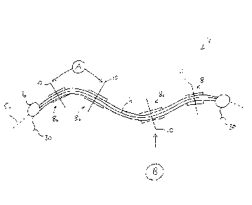
Finally, referring to Figure 4, there is shown a plan view of an apparatus
according to a further embodiment of the present invention, generally
indicated as
102. The apparatus 102 comprises an elongate flexible member 104, surrounded
at
its edge by a generally cylindrical buoyant barrier 106. The flexible member
104 is
provided with a plurality of spaced apart rigid platforms 108. Each platform
108 is
provided with a coupling 110, for connecting to a suitable means for
generating
energy from movement of the platform. Details of the apparatus 102 shown in
Figure
4 are analogous to those shown in Figures 2 and 3 and described hereinbefore.
The apparatus 102 of Figure 4 is able to respond to and generate energy
from waves travelling at all directions relative to the apparatus. Thus, waves
travelling parallel to the longitudinal axis of the apparatus 102 will induce
relative
movement between the platforms 108 displaced axially along the flexible
member. In
addition, waves travelling perpendicular to the longitudinal axis will induce
relative
movement between adjacent platforms either side of the longitudinal axis. The
apparatus 102 may be deployed singularly. Alternatively, an array may be
provided
comprising a plurality of the apparatus 102 arranged in end to end
relationship and/or
side by side, as required.