Note : Les descriptions sont présentées dans la langue officielle dans laquelle elles ont été soumises.
CA 02857639 2014-05-30
WO 2013/105982 PCT/US2012/023700
SAFETY SHIELD FOR FLUID SPECIMEN CONTAINER
BACKGROUND OF THE INVENTION
1. Field of the Disclosure
[0001] The present disclosure relates generally to a container assembly for
collecting a
fluid specimen. More particularly, the present disclosure relates to a
container assembly
including a shield that may be used to cover a needle disposed in the
container assembly to
prevent re-exposure of the needle.
2. Description of the Related Art
[0002] To conduct laboratory testing on biological fluid samples, such as
urine, it is
necessary to provide a container for collecting the fluid sample. These
collection containers
typically include a cup-shaped container with a removable cover. Once a fluid
sample has
been collected in the container, the cover is reapplied. The collection
container may then be
transported to a laboratory or other testing facility where a sample of the
collected specimen
is extracted for test purposes.
[0003] To simplify the sample extraction process, prior collection containers
have used
covers which not only cover and seal the collection container, but also
provide for the use of
an extraction device which permits the extraction of a sample of the fluid
specimen. Such
covers may include a cavity which supports a tube extending within the cavity
to the lower
end of the cup-shaped container in fluid communication with the specimen
contained within
the container. The tube or the cover may include a needle so that an air-
evacuated collection
device, such as a specimen collection tube, may be attached thereto to draw a
portion of the
collected sample thereinto without removal of the cover. In these
configurations, the sample
can be removed without spilling or contaminating the sample and/or cavity
area. Subsequent
samples may be drawn from the collection container by using a plurality of
collection tubes.
However, prior collection containers typically include an exposed needle which
may result in
a patient and/or healthcare worker receiving an inadvertent needle stick
injury. Accordingly,
there is a need for a collection container assembly which allows for improved
collection,
transportation, and subsequent dispensing of a fluid specimen.
SUMMARY OF THE INVENTION
[0004] The present disclosure provides a container assembly which includes a
shield
disposed at least partially within a receiving cavity of a receptacle of a
lid. The shield
1
CA 02857639 2014-05-30
WO 2013/105982 PCT/US2012/023700
provides a physical barrier that at least partially covers and/or blocks an
entrance to the
receiving cavity to prevent a patient and/or healthcare worker from needle
stick injuries. In
one embodiment, the shield is adapted to receive a stopper of a collection
tube, and the shield
is transitionable between a locked position in which the shield is restrained
within an open
end of the receptacle, and an unlocked position in which the shield is movable
within the
receiving cavity of the receptacle. In this embodiment, with the shield in the
unlocked
position, the collection tube is moveable axially within the receiving cavity
of the receptacle
so that a stopper of the collection tube is pierceable by a cannula disposed
within the
receiving cavity of the receptacle. In this manner, with the stopper of the
collection tube
engaged with the cannula, a fluid specimen disposed in a chamber of the
container can be
transferred to a tube chamber of the collection tube via the cannula.
[0005] In accordance with an embodiment of the present invention, a container
assembly
for collecting a fluid specimen includes a container having a first end, a
second end, and a
sidewall extending therebetween and defining a chamber for receiving the fluid
specimen.
The container assembly of this embodiment includes a lid attachable to the
container to at
least partially close the first end thereof, the lid having an upper surface
and an elongate
receptacle extending from the upper surface into the chamber of the container,
the receptacle
having an open end defined within the upper surface of the lid, a lower end, a
locking portion,
and a wall member defining a receiving cavity and extending between the open
end and the
lower end, the lower end of the receptacle including a cannula in fluid
communication with
the chamber of the container. The container assembly further includes a shield
disposed at
least partially within the receiving cavity of the receptacle, the shield
transitionable between a
locked position in which the shield is restrained within the open end of the
receptacle, and an
unlocked position in which the shield is movable within the receiving cavity
of the
receptacle.
[0006] In one configuration, the cannula includes a first end positioned
within the
receiving cavity and a second end in fluid communication with the chamber of
the container.
The container assembly further includes a closure member engaged with the
first end of the
cannula and transitionable between a sealed position in which the closure
member prevents
fluid communication between the chamber of the container and the receiving
cavity of the
receptacle, and an open position in which the closure member allows fluid
communication
between the chamber of the container and the receiving cavity of the
receptacle. In one
configuration, the shield includes a locking member transitionable from the
locked position in
which the locking member is engaged with the locking portion of the receptacle
so that the
2
CA 02857639 2014-05-30
WO 2013/105982 PCT/US2012/023700
shield is restrained within the open end of the receptacle, and the unlocked
position in which
the locking member is disengaged from the locking portion of the receptacle so
that the shield
is movable within the receiving cavity of the receptacle. The locking member
of the shield
may also include a first end and a second end with the first end of the
locking member
engaging the locking portion of the receptacle in the locked position. In one
configuration,
actuation of the second end of the locking member in a first direction, pivots
the first end of
the locking member in a second direction, the second direction being different
than the first
direction. The locking member may include at least one pivotable latch. In
another
embodiment, the locking member may include a plurality of pivotable latches
disposed about
a perimeter of the shield. In the locked position, the shield is locked within
the receiving
cavity above the first end of the cannula. The shield may include a first
shield end having a
shield bottom wall defining an aperture. In the unlocked position, the shield
is movable
within the receiving cavity of the receptacle so that a portion of the cannula
extends through
the aperture of the shield bottom wall.
[0007] In one configuration, the lid includes a sealing portion about a
perimeter of the lid
to seal the chamber of the container. The lid may be threadingly attachable to
the container.
In another embodiment, the lid may be interference fit to a portion of the
container. The
second end of the container further includes a bottom wall having an inner
convex shaped
surface and an outer concave shaped surface.
[0008] In accordance with another embodiment of the present invention, a
container
assembly for collecting a fluid specimen includes a container having a first
end, a second end,
and a sidewall extending therebetween and defining a chamber for receiving the
fluid
specimen. The container assembly of this embodiment includes a lid attachable
to the
container to at least partially close the first end thereof, the lid having an
upper surface and an
elongate receptacle extending from the upper surface into the chamber of the
container, the
receptacle having an open end defined within the upper surface of the lid, a
lower end, a
locking portion, and a wall member defining a receiving cavity and extending
between the
open end and the lower end, the lower end of the receptacle including a
cannula in fluid
communication with the chamber of the container. The container assembly
further includes a
shield disposed at least partially within the receiving cavity of the
receptacle and adapted to
receive a stopper of a collection tube, the shield transitionable between a
locked position in
which the shield is restrained within the open end of the receptacle, and an
unlocked position
in which the shield is movable within the receiving cavity of the receptacle.
3
CA 02857639 2014-05-30
WO 2013/105982 PCT/US2012/023700
[0009] In one configuration, the cannula includes a first end positioned
within the
receiving cavity and a second end in fluid communication with the chamber of
the container.
The container assembly further includes a closure member engaged with the
first end of the
cannula and transitionable between a sealed position in which the closure
member prevents
fluid communication between the chamber of the container and the receiving
cavity of the
receptacle, and an open position in which the closure member allows fluid
communication
between the chamber of the container and the receiving cavity of the
receptacle. In one
configuration, the shield includes a locking member transitionable from the
locked position in
which the locking member is engaged with the locking portion of the receptacle
so that the
shield is restrained within the open end of the receptacle, and the unlocked
position in which
the locking member is disengaged from the locking portion of the receptacle so
that the shield
is movable within the receiving cavity of the receptacle. In one embodiment,
with the shield
restrained within the open end of the receptacle in the locked position and
the stopper of the
collection tube received within the shield and moved axially within the
receiving cavity of the
receptacle, the stopper disengages the locking member of the shield from the
locking portion
of the receptacle to move the locking member from the locked position to the
unlocked
position. With the locking member of the shield in the unlocked position, the
collection tube
is moveable axially within the receiving cavity of the receptacle so that the
stopper of the
collection tube is engaged with the first end of the cannula, wherein the
stopper is pierceable
by the first end of the cannula.
[0010] In accordance with another embodiment of the present invention, a
container
assembly for collecting a fluid specimen includes a container having a first
end, a second end,
and a sidewall extending therebetween and defining a chamber for receiving the
fluid
specimen. The container assembly of this embodiment includes a lid attachable
to the
container to at least partially close the first end thereof, the lid having an
upper surface and an
elongate receptacle extending from the upper surface into the chamber of the
container, the
receptacle having an open end defined within the upper surface of the lid, a
lower end, and a
wall member defining a receiving cavity and extending between the open end and
the lower
end, the lower end of the receptacle including a cannula in fluid
communication with the
chamber of the container. The container assembly further includes a shield
disposed at least
partially within the receiving cavity of the receptacle, the shield
transitionable between a first
position in which the shield is spaced a distance from the cannula, and a
second position in
which the shield is disposed at least partially about the cannula.
4
CA 02857639 2014-05-30
WO 2013/105982 PCT/US2012/023700
BRIEF DESCRIPTION OF THE DRAWINGS
[0011] FIG. 1 is an exploded, perspective view of a container assembly in
accordance with
an embodiment of the present invention.
[0012] FIG. 2 is an assembled, perspective view of the container assembly of
FIG. 1, with
a shield in a locked position in accordance with an embodiment of the present
invention.
[0013] FIG. 3A is a cross-sectional view of the container assembly of FIG. 1
taken along
line 3A-3A of FIG. 2 in accordance with an embodiment of the present
invention.
[0014] FIG. 3B is an enlarged partial cross-sectional view of the container
assembly of
FIG. 1 taken along section 3B of FIG. 3A in accordance with an embodiment of
the present
invention.
[0015] FIG. 3C is an enlarged partial cross-sectional view of the container
assembly of
FIG. 1 taken along section 3C of FIG. 3A in accordance with an embodiment of
the present
invention.
[0016] FIG. 4A is the cross-sectional view of FIG. 3A, with a stopper of a
collection tube
engaging a portion of a shield in a locked position in accordance with an
embodiment of the
present invention.
[0017] FIG. 4B is an enlarged partial cross-sectional view of the container
assembly of
FIG. 4A taken along section 4B in accordance with an embodiment of the present
invention.
[0018] FIG. 5 is the cross-sectional view of FIG. 4A, with the shield in an
unlocked
position in accordance with an embodiment of the present invention.
[0019] FIG. 6 is the cross-sectional view of FIG. 4A, with the stopper of the
collection
tube engaging a cannula in accordance with an embodiment of the present
invention.
[0020] FIG. 7 is an exploded perspective view of a container assembly in
accordance with
an embodiment of the present invention.
[0021] FIG. 8 is an assembled perspective view of the container assembly of
FIG. 7 in
accordance with an embodiment of the present invention.
[0022] FIG. 9A is a cross-sectional view of the container assembly of FIG. 7
taken along
line 9A-9A of FIG. 8 in accordance with an embodiment of the present
invention.
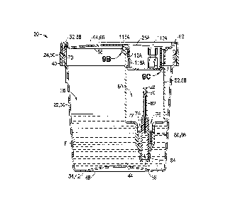
[0023] FIG. 9B is an enlarged partial cross-sectional view of the container
assembly of
FIG. 7 taken along section 9B of FIG. 9A in accordance with an embodiment of
the present
invention.
CA 02857639 2014-05-30
WO 2013/105982 PCT/US2012/023700
[0024] FIG. 9C is an enlarged partial cross-sectional view of the container
assembly of
FIG. 7 taken along section 9C of FIG. 9A in accordance with an embodiment of
the present
invention.
[0025] FIG. 10A is the cross-sectional view of FIG. 9A, with a stopper of a
collection
tube engaging a portion of a shield in a locked position in accordance with an
embodiment of
the present invention.
[0026] FIG. 10B is an enlarged partial cross-sectional view of the container
assembly of
FIG. 10A taken along section 10B in accordance with an embodiment of the
present
invention.
[0027] FIG. 11 is the cross-sectional view of FIG. 10A, with the shield in an
unlocked
position in accordance with an embodiment of the present invention.
[0028] FIG. 12 is the cross-sectional view of FIG. 10A, with the stopper of
the collection
tube engaging a cannula in accordance with an embodiment of the present
invention.
DETAILED DESCRIPTION
[0029] For purposes of the description hereinafter, the terms "upper",
"lower", "right",
"left", "vertical", "horizontal", "top", "bottom", "lateral", "longitudinal",
and derivatives
thereof shall relate to the invention as it is oriented in the drawing
figures. However, it is to
be understood that the invention may assume various alternative variations,
except where
expressly specified to the contrary. It is also to be understood that the
specific devices
illustrated in the attached drawings, and described in the following
specification, are simply
exemplary embodiments of the invention. Hence, specific dimensions and other
physical
characteristics related to the embodiments disclosed herein are not to be
considered as
limiting.
[0030] Referring to FIGS. 1-3A, a container assembly 20 includes a container
22, a lid 24,
a shield 26, and a closure or sleeve member 28. An exemplary container
assembly in
accordance with the present disclosure may be used to safely collect a fluid
specimen,
transport the fluid specimen, and draw a sample of the fluid specimen without
contamination
of the fluid specimen and without receiving a needle stick injury.
[0031] Referring to FIGS. 1-3A, container 22 generally includes a sidewall 30
extending
between a first, open end 32 and a second, closed end 34. Sidewall 30 defines
interior or
collection chamber 36 for receiving a fluid specimen such as fluid specimen F
(FIGS. 3A-6).
In one embodiment, sidewall 30 of container 22 comprises a slightly tapering,
tubular vessel
6
CA 02857639 2014-05-30
WO 2013/105982 PCT/US2012/023700
having continuous, tapered sidewalls 30. Open end 32 defines a lip 38 and
includes an
exterior threaded portion 40 around a perimeter thereof. Closed end 34
comprises a bottom
wall 42 having a convex shaped inner surface 44 and a concave shaped outer
surface 46 to
assist in maximum sample collection of small volume fluids in the bottom of
container 22. In
one embodiment, collection chamber 36 of container 22 is suitable for holding
biologically
hazardous materials. In one embodiment, container 22 and lid 24 may be formed
from any
conventional material such as, for example, a polymeric resin. Polymeric
resins are well
known in the art and include, for example, polyethylene, polycarbonate,
polystyrene, and
similar polymeric resinous materials.
[0032] In one embodiment, sidewall 30 of container 22 may contain a fill level
indicator
(not shown) which identifies a maximum fill level for collecting a fluid
specimen such as
fluid specimen F (FIGS. 4A-6). The fill level indicator is positioned so that
the fluid
specimen will not exceed the capacity of collection chamber 36 when container
22 is filled
and lid 24 is attached to container 22.
[0033] Referring to FIGS. 1-3A, lid 24 generally includes a flange 50
extending around its
outer rim and is sized to provide a tight fit when lid 24 is placed over
container 22. Flange 50
of lid 24 includes ribs 51 disposed on an exterior surface of flange 50. Ribs
51 of lid 24
provide a gripping means to allow a user or a tool to more easily grasp lid 24
when attaching
lid 24 to container 22. Lid 24 also includes an elongate receptacle 52
extending into
container 22 towards bottom wall 42 of container 22. Receptacle 52 includes an
open end 54,
an opposing lower end 56, and a wall member 58 extending from open end 54 to
lower end
56 and defining a receiving cavity 60. In one embodiment, receiving cavity 60
is sized and
shaped to receive a portion of shield 26 and a collection tube 200 including a
stopper 202 and
defining a tube chamber 204 (FIGS. 4A-6 and 10A-12) as will be described in
more detail
below.
[0034] Referring to FIGS. 1-3A, in one embodiment, lid 24 comprises a
generally disc-
shaped component having an outer or peripheral zone 62 and an inner or central
zone 64
including an upper surface 66 and an opposing under surface 68 (FIGS. 3A and
9A). Flange
50 extends downward from peripheral zone 62 of lid 24. Referring to FIG. 3A,
in one
embodiment, flange 50 extends downward from peripheral zone 62 to partially
hide under
surface 68 of lid 24. Flange 50 includes an inner surface which contains a
means for
sealingly engaging lid 24 with open end 32 of container 22. In one embodiment,
flange 50 of
lid 24 includes an interior threaded portion 70 (FIGS. 3A, 4A, 5, and 6). In
such an
embodiment, lid 24 is threadingly connectable to open end 32 of container 22
via mating
7
CA 02857639 2014-05-30
WO 2013/105982 PCT/US2012/023700
threaded portions 40, 70 as shown in FIG. 3A. In other embodiments, the
sealing portion of
lid 24 may include a snap fit mechanism, a ball detent, an interference fit
mechanism, locking
tabs, a spring loaded locking mechanism, a latch, or other similar mechanism
to sealingly
engage lid 24 to container 22, i.e., to prevent a fluid specimen contained
within container 22
and lid 24 from leaking out and to prevent contaminants from getting in.
[0035] Open end 54 of receptacle 52 is disposed at central zone 64. Referring
to FIG. 2, in
one embodiment, open end 54 of receptacle 52 is offset towards peripheral zone
62. Wall
member 58 of receptacle 52 which defines receiving cavity 60 is continuous
with and part of
the molded surface of lid 24. Open end 54 of receptacle 52 is defined within
upper surface
66 of lid 24 and receptacle 52 extends from upper surface 66 into chamber 36
of container 22,
with lid 24 attached to container 22. Referring to FIG. 3B, in one embodiment,
receptacle 52
includes a locking portion 140 having a first locking portion vertical wall
142, a second
locking portion vertical wall 144, and a locking portion horizontal wall 146
extending
between vertical walls 142, 144 and defining a locking surface 148. Referring
to FIGS. 3B
and 3C, in one embodiment, second vertical wall 144 and wall member 58 of
receptacle 52
include a retention ring 150 as will be described in more detail below.
[0036] Referring to FIG. 3A, wall member 58 of receptacle 52 includes a
cannula end
horizontal wall 72 and a cannula end vertical wall 74 which together define a
cannula
opening 76 in which a cannula 80 is received. In one embodiment, cannula 80 is
continuous
with and part of receptacle 52. Cannula 80 generally includes a first end 82,
an opposing
second end 84, and a cannula wall 86 extending from first end 82 to second end
84. Cannula
wall 86 defines an elongate aperture 88 which spans the extent of cannula 80
so that cannula
80 is cannulated along its entire length. In this manner, elongate aperture 88
is in fluid
communication with chamber 36 of container 22. In one embodiment, first end 82
of cannula
80 projects from cannula end horizontal wall 72 into receptacle 52 in a
position to pierce
stopper 202 of collection tube 200 when collection tube 200 is received within
receiving
cavity 60 of receptacle 52. With collection tube 200 received within receiving
cavity 60 and
with stopper 202 pierced by first end 82 of cannula 80, chamber 36 of
container 22 is in fluid
communication with tube chamber 204 of collection tube 200 via elongate
aperture 88 of
cannula 80 as will be described in more detail below. In one embodiment, first
end 82 of
cannula 80 comprises needle point 90 to pierce stopper 202 of collection tube
200.
[0037] Referring to FIGS. 1-3A, shield 26 generally includes a first shield
end 100, an
opposing second shield end 102, and a shield sidewall 104 extending from end
100 to end
102. First shield end 100 includes a shield bottom wall 106 which defines an
aperture 108
8
CA 02857639 2014-05-30
WO 2013/105982 PCT/US2012/023700
and includes a protruding ring portion 109 which extends outward from shield
bottom wall
106. Referring to FIG. 1, in one embodiment, shield bottom wall 106 defines
aperture 108 in
a central region. Aperture 108 is sized to receive first end 82 of cannula 80
therethrough as
will be described in more detail below. In one embodiment, referring to FIG.
1, shield
sidewall 104 includes a plurality of sections defining receiving slots 110
therebetween.
Receiving slots 110 are sized to receive a locking member 112 therein. In one
embodiment,
locking member 112 can be pivotably secured between adjacent sections of
shield sidewall
104 via connection members 114 so that locking member 112 can be pivoted from
a first,
locked position to a second, unlocked position as will be described in more
detail below.
Referring to FIG. 4B, each locking member 112 includes a locking end 116 and
an opposing
engagement end 118 including an interior engagement surface 120.
[0038] Shield bottom wall 106 and shield sidewall 104 together define a shield
receiving
cavity 122 which is sized and adapted to receive a portion of stopper 202 of
collection tube
200 as will be described in more detail below. Retelling to FIG. 1, in one
embodiment,
locking member 112 of shield 26 may comprise at least one pivotable latch. In
other
embodiments, locking member 112 may comprise a plurality of pivotable or
flexible latches
disposed about a perimeter of shield 26. Locking member 112 may be integral to
shield 26
and may be molded from plastic or stamped from metal. Referring to FIG. 1, in
one
embodiment, locking members 112 are movably mounted relative to shield
sidewall 104 via
connection members 114 so that each locking member 112 may be simultaneously
pivoted or
flexed to allow for complete un-latching of shield 26 as will be described in
more detail
below. In this manner, shield 26 may be transitionable between a locked
position in which a
portion of shield 26 may be restrained within open end 54 of receptacle 52,
and an unlocked
position in which shield 26 is movable within receiving cavity 60 of
receptacle 52.
[0039] Refening to FIG. 3A, sleeve member 28 generally includes a self-sealing
sleeve
secured over cannula 80 so that sleeve member 28 covers needle point 90 of
first end 82 of
cannula 80 in a sealed position to prevent fluid communication between chamber
36 of
container 22 and receiving cavity 60 of receptacle 52. Sleeve member 28 is
pierceable by
needle point 90 of cannula 80 so that sleeve member 28 is transitionable from
the sealed
position to an open position in which sleeve member 28 allows fluid
communication between
chamber 36 of container 22 and receiving cavity 60 of receptacle 52. Also,
with sleeve
member 28 in such an open position, tube chamber 204 of collection tube 200
may be in fluid
communication with chamber 36 of container 22 when collection tube 200 is
inserted in
9
CA 02857639 2014-05-30
WO 2013/105982 PCT/US2012/023700
receiving cavity 60 of receptacle 52 and stopper 202 is pierced by needle
point 90 of cannula
80 as will be discussed in more detail below.
[0040] In one embodiment, sleeve member 28 comprises a resilient material. For
example,
sleeve member 28 is preferably a unitary device molded of any flexible,
elastomeric material
conventionally used for fabricating gas-proof closures. Sleeve member 28 may
be formed of
a natural rubber material, polyurethane elastomers, butyl rubbers, or similar
materials. It is
contemplated that sleeve member 28 is formed of a material having a Shore A
hardness of
approximately 35 to 80. It is also envisioned that sleeve member 28 can have
other material
hardness values that would provide an appropriate self-sealing material to
prevent fluid
communication between chamber 36 of container 22 and receiving cavity 60 of
receptacle 52
with sleeve member 28 in a sealed position, and allow fluid communication
therebetween
with sleeve member 28 in an open position.
[0041] Referring to FIGS. 3A-3C, the use of shield 26 to cover and/or block
the entrance
to receiving cavity 60 of receptacle 52 containing needle point 90 of cannula
80 will now be
described. Shield 26 may be positioned at least partially within receiving
cavity 60 of
receptacle 52. In a locked position, shield 26 is restrained within receiving
cavity 60 of
receptacle 52. For example, in the locked position, locking members 112 of
shield 26 are
orientated as shown in FIGS. 3A and 3B so that locking end 116 of locking
member 112
engages locking surface 148 of locking portion 140 of receptacle 52 as shown
in FIG. 3B. In
this manner, shield 26 is restrained within receiving cavity 60 of receptacle
52, i.e.,
significant relative movement between shield 26 and receptacle 52 is
prevented. In one
embodiment, referring to FIG. 3C, wall member 58 includes retention ring 150
which
provides a physical barrier to resist movement of protruding ring portion 109
of shield 26. In
this manner, retention ring 150 provides an additional securement mechanism to
restrain
shield 26 within receiving cavity 60 of receptacle 52 in the locked position.
[0042] In the locked position, shield 26 is particularly advantageous in that
it allows a user,
such as a patient and/or healthcare worker, to safely handle container
assembly 20 without
receiving needle stick injuries from needle point 90 of cannula 80. With
shield 26 in the
locked position as described above, shield 26 provides a physical barrier
preventing the
fingers of a user from being inserted within receiving cavity 60 of receptacle
52 and
contacting needle point 90 of cannula 80. In this manner, the user is
prevented from needle
stick injuries and the user can conveniently and safely handle container
assembly 20 and
withdraw a fluid sample from chamber 36 of container 22 into a collection tube
200 as will
be described in more detail below.
CA 02857639 2014-05-30
WO 2013/105982 PCT/US2012/023700
[0043] Referring to FIGS. 4A-6, the use of container assembly 20 and
collection tube 200
to withdraw a fluid specimen F from chamber 36 of container 22 into tube
chamber 204 of
collection tube 200 will now be described.
[0044] Container assembly 20 is intended to be used in the first instance by a
patient, and
then by a doctor, nurse, or laboratory technician in the second instance for
sampling of the
collected fluid specimen in container 22. The patient uses container 22 by
removing lid 24
and then providing the fluid specimen. Lid 24 can then be attached to
container 22, and
container assembly 20 containing fluid specimen F given to the test person. At
this time,
when the test person is ready to draw the fluid specimen for testing,
collection tube 200
including stopper 202 having an exterior engagement surface 206 (FIG. 4B) and
defining
tube chamber 204 is inserted into open end 54 of receptacle 52 as shown in
FIG. 4A.
[0045] Once shield 26 is disposed at least partially within receiving cavity
60 of receptacle
52 in the locked position as described above and stopper 202 of collection
tube 200 is
positioned adjacent to receiving cavity 122 (FIG. 1) of shield 26 as shown in
FIGS. 4A and
4B, collection tube 200 can be moved axially into receiving cavity 60 of
receptacle 52.
Referring to FIGS. 4A and 4B, as collection tube 200 is moved into receiving
cavity 60 of
receptacle 52 in a direction generally along arrow E (FIG. 4B), exterior
engagement surface
206 of stopper 202 cooperates with interior engagement surface 120 of each
locking member
112 of shield 26 and actuates or pushes engagement end 118 of locking member
112 outward
in a direction generally along arrow A. Movement of engagement end 118 of
locking
member 112 of shield 26 in the direction generally along arrow A causes
locking end 116 of
locking member 112 of shield 26 to pivot or move in a direction generally
along arrow B
(FIG. 4B) so that locking end 116 disengages from locking surface 148 of
locking portion
140 of receptacle 52. In this manner, shield 26 is transitioned from the
locked position shown
in FIGS. 3A and 3B to the unlocked position as shown in FIGS. 5 and 6. In this
manner,
stopper 202 of collection tube 200 functions as a key to unlock shield 26 from
the locked
position to allow shield 26 and collection tube 200 to move within receiving
cavity 60 of
receptacle 52 as shown in FIGS. 5 and 6. Stopper 202 of collection tube 200
cooperates with
shield 26 to enable each locking member 112 of shield 26 to be simultaneously
moved from
the locked position shown in FIGS. 3A and 3B to the unlocked position shown in
FIGS. 5
and 6. In one embodiment, shield 26 is sized and shaped to be engageable with
stopper 202
of collection tube 200 in the manner described above, but not to allow
interaction with a
human finger to unlock shield 26 from its locked position relative to
receptacle 52. Further,
11
CA 02857639 2014-05-30
WO 2013/105982 PCT/US2012/023700
shield 26 is sized and shaped so that a human finger would not be able to
function as a key to
simultaneously unlock each of locking members 112 of shield 26.
[0046] With the locking members 112 of shield 26 in the unlocked position,
collection tube
200 can be further moved axially within receiving cavity 60 of receptacle 52
as shown in
FIGS. 5 and 6 until stopper 202 engages first end 82 of cannula 80 as shown in
FIG. 6.
Because needle point 90 of cannula 80 projects into receiving cavity 60 of
receptacle 52 as
discussed above, as collection tube 200 is moved within receiving cavity 60 of
receptacle 52,
needle point 90 is capable of piercing stopper 202 of collection tube 200 so
that chamber 36
of container 22 is in fluid communication with tube chamber 204 of collection
tube 200 via
elongate aperture 88 of cannula 80. This fluid communication is established
because as
collection tube 200 is inserted within receiving cavity 60 of receptacle 52 so
that stopper 202
engages first end 82 of cannula 80, stopper 202 of collection tube 200 engages
and pushes
down sleeve member 28 over first end 82 of cannula 80 as shown in FIG. 6.
Because sleeve
member 28 is formed from a resilient flexible material, when collection tube
200 is removed
from receiving cavity 60 of receptacle 52, sleeve member 28 is capable of
returning to its
original position to re-seal and prevent fluid communication between elongate
aperture 88 of
cannula 80 and receiving cavity 60 of receptacle 52 as shown in FIGS. 4A and
5.
[0047] With collection tube 200 positioned as shown in FIG. 6 with needle
point 90 of
cannula 80 piercing stopper 202, a test person may draw or transfer fluid
specimen F from
chamber 36 of container 22 into tube chamber 204 of collection tube 200 (FIG.
6, fluid
specimen F1). Once the desired amount of the fluid specimen F1 is received
within tube
chamber 204 as shown in FIG. 6, collection tube 200 can then be withdrawn or
retracted
from receiving cavity 60 of receptacle 52. If needed, a second, third, etc.,
collection tube can
be inserted and forced over needle point 90 as described above to withdraw
additional
portions of the fluid specimen F contained within chamber 36 of container 22.
Once the final
desired portion of fluid specimen F is withdrawn, container assembly 20 may
then be
discarded or further handled as desired with shield 26 in the locked position,
as shown in
FIGS. 3A and 3B, to prevent needle stick injuries to the user. In one
embodiment, shield 26
is returned to its locked position relative to receptacle 52 via engagement
with stopper 202 of
collection tube 200 as shown in FIGS. 4A-6. In such an embodiment, retention
ring 150
provides a physical barrier that prevents shield 26 from being removed from
receptacle 52.
In other embodiments, a spring, such as a coil compression spring, may be used
to safely
return shield 26 to its locked position.
12
CA 02857639 2016-04-07
WO 2013/105982 PCT/US2012/023700
[0048] FIGS. 7-12 illustrate another exemplary embodiment of shield 26. The
embodiment illustrated in FIGS. 7-12 includes similar components to the
embodiment
illustrated in FIGS. 1-6, and the similar components are denoted by the same
reference
numbers used in FIGS. 1-6. Components of the alternate embodiment of shield 26
are
denoted by a reference number followed by the letter "A".
[0049] Referring to FIGS. 7-10B, a shield 26A includes a locking end 116A and
opposing
an engagement end 118A. As shown in FIG. 9B, an upper region of a locking
member 112A
includes locking end 116A which engages locking surface 148 of locking portion
140 of
receptacle 52. In a manner similar as described above regarding shield 26,
with stopper 202
of collection tube 200 inserted in the position shown in FIGS. 10A and 10B, as
collection
tube 200 is moved into receiving cavity 60 of receptacle 52 in a direction
generally along
arrow E (FIG. 10B), exterior engagement surface 206 of stopper 202 cooperates
with an
interior engagement surface 120A of each locking member 112A of shield 26A and
actuates
or pushes engagement end 118A of locking member 112A outward in a direction
generally
along arrow C. Movement of engagement end 118A of locking member 112A of
shield 26A
in the direction generally along arrow C causes locking end 116A of locking
member 112A
of shield 26A to pivot or move in a direction generally along arrow I) (FIG.
10B) so that
locking end 116A disengages from locking surface 148 of locking portion 140 of
receptacle
52. In this manner, shield 26A is transitioned from the locked position shown
in FIGS. 9A
and 9B to the unlocked position as shown in FIGS. 11 and 12. In this manner,
stopper 202 of
collection tube 200 functions as a key to unlock shield 26A from the locked
position to allow
shield 26A and collection tube 200 to move within receiving cavity 60 of
receptacle 52 as
shown in FIGS. 11 and 12.
=
13